Supported Interfaces
This section describes the DPU-supported interfaces. Each numbered interface that is referenced in the figures is described in the following table with a link to detailed information.
The figures in the sections below are for illustration purposes only.
Interfaces of MBF2H332A-AECOT, MBF2H332A-AEEOT, MBF2H332A-AENOT
|
Component Side |
Print Side |

|

|
|
Item |
Interface |
Description |
|
1 |
DPU |
DPU IC 8 cores |
|
2 |
PCI Express Interface |
PCIe Gen 4.0 through an x8 edge connector |
|
3 |
Networking Ports |
Ethernet traffic is transmitted through the DPU SFP56 connectors. The SFP56 connectors allow for the use of modules, optical and passive cable interconnect solutions. By default, the port cages of this group of OPNs are set to operate in SFP28 mode (default card firmware setting). |
|
4 |
Networking Ports LEDs Interface |
One bi-color LED per port for the link and physical status |
|
5 |
DDR4 SDRAM On-Board Memory |
8 units of SDRAM for a total of 16GB @ 3200MT/s single DDR4 channel, 64bit + 8bit ECC, solder-down memory |
|
6 |
NC-SI Management Interface |
Connection for remote sideband management |
|
7 |
USB 4-pin vertical connector |
Mounted on the DPU for OS image loading |
|
8 |
1GbE OOB Management Interface |
1GbE BASE-T OOB management interface. |
|
9 |
RTC Battery |
Battery holder for RTC |
|
10 |
eMMC Interface |
x8 NAND flash |
Interfaces of MBF2M355A-VECOT, MBF2M355A-VESOT
|
Component Side |
Print Side |

|

|
|
Item |
Interface |
Description |
|
1 |
DPU |
DPU IC 8 cores |
|
2 |
PCI Express Interface |
PCIe Gen 4.0 through an x16 edge connector |
|
3 |
Networking Interface |
Network traffic is transmitted through the DPU QSFP56 connector. The QSFP56 connector allow for the use of modules, and optical and passive cable interconnect solutions. |
|
4 |
Networking Ports LEDs Interface |
One bi-color LED per port for the link and physical status |
|
5 |
DDR4 SDRAM On-Board Memory |
8 units of SDRAM for a total of 32GB @ 3200MT/s single DDR4 channel, 64bit + 8bit ECC, solder-down memory |
|
6 |
NC-SI Management Interface |
Connection for remote sideband management |
|
7 |
USB 4-pin vertical connector (default) |
Mounted on the DPU for OS image loading |
|
8 |
1GbE OOB Management Interface |
1GbE BASE-T OOB management interface |
|
9 |
RTC Battery |
Battery holder for RTC |
|
10 |
eMMC Interface |
x8 NAND flash |
Interfaces of MBF2H512C-AECOT, MBF2H512C-AESOT, MBF2H512C-AEUOT, MBF2H532C-AECOT, MBF2H532C-AESOT
|
Component Side |
Print Side |

|

|
|
Item |
Interface |
Description |
|
1 |
DPU |
DPU IC 8 cores |
|
2 |
PCI Express Interface |
PCIe Gen 4.0 through an x8 edge connector |
|
3 |
Networking Ports |
The Ethernet traffic is transmitted through the DPU SFP56 connectors. The SFP56 connectors allow the use of modules, optical and passive cable interconnect solutions. By default, the port cages of this group of OPNs are set to operate in SFP28 mode (default card firmware setting). |
|
4 |
Networking Ports LEDs Interface |
One bi-color I/O LED per port to indicate link and physical status |
|
5 |
DDR4 SDRAM On-Board Memory |
8 units of SDRAM for a total of 16GB/32GB @ 3200MT/s single DDR4 channel, 64bit + 8bit ECC, solder-down memory |
|
6 |
NC-SI Management Interface |
Connectivity for remote sideband management (NC-SI over RBT). MBF2H512C-AECOT, MBF2H512C-AESOT, MBF2H512C-AEUOT: a 30-pin NC-SI connector is populated MBF2H532C-AECOT, MBF2H532C-AESOT: the NC-SI connector type differs per the product HW version: In the Engineering samples, a 30-pin NC-SI connector is populated, whereas in HW versions B3 and up, a 20-pin NC-SI connector is populated |
|
7 |
USB 4-pin Vertical Interface |
Used for OS image loading |
|
8 |
1GbE OOB Management Interface |
1GbE BASE-T OOB management interface |
|
9 |
RTC Battery |
Battery holder for RTC |
|
10 |
eMMC Interface |
x8 NAND flash |
|
11 |
BMC |
Embedded BMC on DPU |
|
12 |
MMCX RA PPS IN/OUT |
Enables PPS IN/OUT |
Interfaces of MBF2H516A-CEEOT, MBF2H516A-CENOT, MBF2M516A-CECOT, MBF2M516A-CEEOT, MBF2M516A-CENOT
|
Component Side |
Print Side |

|

|
|
Item |
Interface |
Description |
|
1 |
DPU |
DPU IC 8 cores |
|
2 |
PCI Express Interface |
PCIe Gen 4.0 through an x16 edge connector |
|
3 |
Networking Ports |
The network traffic is transmitted through the DPU QSFP56 connectors. The QSFP56 connectors allow the use of modules, optical and passive cable interconnect solutions. |
|
4 |
Networking Ports LEDs Interface |
One bi-color I/O LED per port to indicate link and physical status |
|
5 |
DDR4 SDRAM On-Board Memory |
8 units of SDRAM for a total of 16GB @ 3200MT/s single DDR4 channel, 64bit + 8bit ECC, solder-down memory |
|
6 |
NC-SI Management Interface |
Connection for remote sideband management |
|
7 |
Mini USB Type B Interface |
Used for OS image loading |
|
8 |
1GbE OOB Management Interface |
1GbE BASE-T OOB management interface |
|
9 |
External PCIe Power Supply Connector |
An external 12V power connection through a 6-pin ATX connector. NOTE: This connector is present on FHHL P-Series DPUs only. It is not present on FHHL E-Series DPUs. |
|
10 |
RTC Battery |
Battery holder for RTC |
|
11 |
eMMC Interface |
x8 NAND flash |
Interfaces of MBF2H516C-CECOT, MBF2H516C-CESOT, MBF2H516C-CEUOT, MBF2M516C-CECOT, MBF2M516C-CESOT, MBF2H536C-CECOT, MBF2H536C-CESOT, MBF2H536C-CEUOT
Component Side |
Print Side |

|

|
Item | Interface | Description |
| 1 | DPU | DPU IC 8 cores |
| 2 | PCI Express Interface | PCIe Gen 4.0 through an x16 edge connector |
3 | Networking Ports | The network traffic is transmitted through the DPU QSFP56 connectors. The QSFP56 connectors allow the use of modules, optical and passive cable interconnect solutions |
4 | Networking Ports LEDs Interface | One bi-color I/O LED per port to indicate link and physical status |
| 5 | DDR4 SDRAM On-Board Memory | 8 units of SDRAM for a total of 16GB/32GB @ 3200MT/s single DDR4 channel, 64bit + 8bit ECC, solder-down memory |
| 6 | NC-SI Management Interface | Connectivity for remote sideband management (NC-SI over RBT). The NC-SI connector type differs per the product HW version: In the Engineering samples, a 30-pin NC-SI connector is populated, whereas in HW versions B200 and up, a 20-pin NC-SI connector is populated For MBF2H536C-CEUOT, a 20-pin NC-SI connector is populated in all HW versions of the DPU |
7 | USB 4-pin vertical connector | Used for OS image loading |
8 | 1GbE OOB Management Interface | 1GbE BASE-T OOB management interface |
| 9 | External PCIe Power Supply Connector | An external 12V power connection through a 6-pin ATX connector. NOTE: This connector is present on FHHL P-Series DPUs only. It is not present on FHHL E-Series DPUs |
| 10 | RTC Battery | Battery holder for RTC |
11 | eMMC Interface | x8 NAND flash |
| 12 | BMC | Embedded BMC on DPU |
| 13 | MMCX RA PPS IN/OUT | Enables PPS IN/OUT |
DPU
NVIDIA® BlueField®-2 DPU is a family of advanced DPU IC solutions that integrate a coherent mesh of 64-bit Arm v8 A72 cores, an NVIDIA® ConnectX®-6 Dx network adapter front-end, and a PCI Express switch into a single chip. The powerful DPU IC architecture includes an Armv8 multicore processor array and enables customers to develop sophisticated applications and highly differentiated feature sets. leverages the rich Arm software ecosystem and introduces the ability to offload the x86 software stack.
At the heart BlueField-2, the ConnectX-6 Dx network offload controller with RDMA and RDMA over Converged Ethernet (RoCE) technology delivers cutting-edge performance for networking and storage applications such as NVMe over Fabrics. Advanced features include an embedded virtual switch with programmable access lists (ACLs), transport offloads, and stateless encaps/decaps of NVGRE, VXLAN, and MPLS overlay protocols.
Encryption
Applies to Crypto enabled OPNs.
DPU addresses the concerns of modern data centers by combining hardware encryption accelerators with embedded software and fully integrated advanced network capabilities, making it an ideal platform for developing proprietary security applications. It enables a distributed security architecture by isolating and protecting each individual workload and providing flexible control and visibility at the server and workload level, controlling risk at the server access layer. builds security into the DNA of the data center and enables prevention, detection, and response to potential threats in real-time. DPU is capable of delivering powerful functionality, including encryption of data-in-motion, bare-metal provisioning, stateful L4 firewall and more.
PCI Express Interface
The DPU supports PCI Express Gen 3.0/4.0 (1.1 and 2.0 compatible) through x8 or x16 edge connectors. The following lists PCIe interface features:
- PCIe Gen 4.0 and 3.0 compliant, 2.0 and 1.1 compatible
- 2.5, 5.0, or 8.0, or 16.0 GT/s link rate x8/x16 lanes
- Auto-negotiates to x16, x8, x4, x2, or x1
- Support for MSI/MSI-X mechanisms
Networking Ports
The network ports of the DPU are compliant with the IEEE 802.3 Ethernet standards listed in Features and Benefits . Traffic is transmitted through the cards' QSFP56/SFP56 connectors. By default, the port cages of this group of OPNs are set to operate in QSFP28/SFP28 mode (default card firmware setting). BlueField-2 DPUs support copper/optic and SR4 modules only.
Networking Ports LEDs Interface
There is one bicolor (Yellow and Green) I/O LED per port to indicate speed and link status.
Link Indications
|
State |
Bi-Color LED (Yellow/Green) |
||||||||||
|
Beacon command for locating the adapter card |
1Hz blinking Yellow |

|
|||||||||
|
Error |
4Hz blinking Yellow Indicates an error with the link. The error can be one of the following:
|

|
|||||||||
|
Physical Activity |
Blinking Green |

|
|||||||||
|
Link Up |
Solid Green |

|

DDR4 SDRAM On-Board Memory
The DPU incorporates 16 or 32GB @ 3200MT/s single DDR4 channel, 64bit + 8bit ECC, solder-down memory.
NC-SI Management Interface
The DPU enables the connection of a Baseboard Management Controller (BMC) to a set of Network Interface Controller (NICs) to enable out-of-band remote manageability. The NC-SI management is supported over RMII and has a connector on the DPU. For connecting to the NCSI RBT interface on the 20 or 30-pin connector, a customized cable is needed based on the NC-SI Management Interface pinouts.
The below table specifies the maximum trace lengths on the board per board type. Please take the maximum trace length on the board into consideration in your design.
The USB to UART cable is not used for NC-SI management purposes.
DPU OPN |
Maximum Trace Length on the Board |
MBF2M516C-CECOT, MBF2M516C-CESOT, MBF2H536C-CECOT, MBF2H536C-CESOT | 10 inch in 20-pin connector |
| MBF2H536C-CEUOT | 10 inch in 20-pin connector |
| MBF2H512C-AECOT, MBF2H512C-AESOT, MBF2H512C-AEUOT, | 5 inch in 30-pin connector |
| MBF2H532C-AECOT, MBF2H532C-AESOT | HW version up to B3: 5 inch in 30-pin connector |
| MBF2H332A-AECOT | DPU HW version C1 and up: 2.9inch |
| MBF2H332A-AEEOT, MBF2H332A-AENOT | DPU HW version C1 and up: 2.9inch |
| MBF2M355A-VECOT, MBF2M355A-VESOT | 3.3inch |
MBF2M516A-CEEOT, MBF2M516A-CENOT | 6.2inch |
UART Interface Connectivity
A UART debug interface is available on the DPU cards via the NC-SI connector. The below table describes the UART interface location and connectivity per the NC-SI connector type on the DPU you have purchased.
|
NC-SI Connector Type |
UART Interface Location and Connectivity |
||||||||||||
|
30-pin |
For DPUs with onboard BMC, the UART interface is that of the BlueField-2 device. For DPUs without onboard BMC, the UART interface is that of the NIC BMC device.
Please note the following: The UART interface is compliant with the TTL 3.3V voltage level. A USB to UART cable that supports TTL voltage levels should be used to connect the UART Interface for Arm console access - see example below. Please refer to UART Cable Installation for installation instructions. 
Warnings:
|
||||||||||||
|
20-pin |
DPUs with onboard BMC hardware: The UART interface is that of the NIC BMC device.
|
USB Interfaces
The USB interface is used to load operating system images. The following table lists the types of onboard USB interfaces and the DPU part numbers that use them.
|
OPN |
USB Interface Type |
USB Cable |
|
MBF2M355A-VECOT, MBF2M355A-VESOT, MBF2H516C-CECOT, MBF2H516C-CESOT, MBF2H516C-CEUOT, MBF2M516C-CECOT, MBF2M516C-CESOT, MBF2H536C-CECOT, MBF2H536C-CESOT, MBF2H536C-CEUOT, MBF2H512C-AECOT, MBF2H512C-AESOT, MBF2H512C-AEUOT, MBF2H532C-AECOT, MBF2H532C-AESOT |
USB 4-pin vertical connector |
Use a 4-pin male connector to a male Type-A cable to connect to the board. The cable is not included in the shipped DPU card box and should be ordered separately as part of the accessories kit (P/N: MBF25-DKIT). 
|
|
MBF2H332A-AECOT, MBF2H332A-AEEOT MBF2H332A-AENOT, MBF2H516A-CEEOT MBF2H516A-CENOT, MBF2M516A-CECOT MBF2M516A-CEEOT, MBF2M516A-CENOT |
Mini USB Type-B connector |
Use a standard USB Type-B to connect. |
BMC Interface
Applies to the following OPNs: MBF2H512C-AECOT, MBF2H512C-AESOT, MBF2H512C-AEUOT, MBF2H532C-AECOT, MBF2H532C-AESOT, MBF2H516C-CECOT, MBF2H516C-CESOT, MBF2H516C-CEUOT, MBF2M516C-CECOT, MBF2M516C-CESOT, MBF2H536C-CECOT, MBF2H536C-CESOT, MBF2H536C-CEUOT.
Some DPUs incorporate local NIC BMC (Baseboard Management Controller) hardware on the board. The BMC SoC (system on a chip) can utilize either shared or dedicated NICs for remote access. The BMC node enables remote power cycling, board environment monitoring, BlueField-2 chip temperature monitoring, board power, and consumption monitoring, and individual interface resets. The BMC also supports the ability to push a boot stream to BlueField-2.
Having a trusted onboard BMC that is fully isolated from the host server ensures the highest security for the DPU boards.
For more information, please refer to Connecting to BMC Interfaces.
1GbE OOB Management Interface
The DPU incorporates a 1GbE RJ-45 out-of-band port that allows the network operator to establish trust boundaries in accessing the management function to apply it to network resources. It can also be used to ensure management connectivity (including the ability to determine the status of any network component) independent of the status of other in-band network components.
10Mb/s and 100Mb/s modes are not supported on this interface.
For DPUs with integrated BMC: 1GbE OOB Management can be performed via the BlueField-2 device or the integrated BMC.
1GbE OOB Management LEDs Interface
There are 2 OOB management LEDs, one green and one amber/yellow. The following table describes LED behavior for DPUs with or with onboard BMC.
|
LED Indications |
Link Activity |
||
|
Green LED |
Amber/Yellow LED |
DPUs with BMC |
DPUs without BMC |
|
OFF |
OFF |
Link off |
Link off |
|
ON |
OFF |
1 Gb/s link / No activity |
Link on (any speed *) / No activity |
|
Blinking |
OFF |
1 Gb/s link / Activity (RX,TX) |
1 Gb/s link / Activity (RX,TX) |
|
OFF |
ON |
Not supported |
100 Mb/s link / No activity |
|
OFF |
Blinking |
100 Mb/s link / Activity (RX,TX) |
|
|
ON |
ON |
10 Mb/s link / No activity |
|
|
Blinking |
Blinking |
10 Mb/s link / Activity (RX,TX) |
|
* On DPUs without BMC, speeds can be 10 Mb/s, 100 Mb/s or 1Gb/s.
RTC Battery
The DPU incorporates a COIN TYPE LITHIUM BATTERY CR621 for RTC (Real Time Clock).
eMMC Interface
The DPU incorporates an eMMC interface on the card's print side. The eMMC is an x8 NAND flash and is used for Arm boot, operating system storage, and disk space. Memory size is either 64GB or 128GB, where 128GB is effectively 40GB with high durability.
External PCIe Power Supply Connector
Applies to FHHL P-Series DPUs with x16 PCIe Gen 4 lanes only, which require supplementary power to be fed via the DPU's onboard 6-pin ATX power supply connector. The power cable that should be connected to this onboard ATX connector is not supplied with the DPU; however, this is a standard cable that is normally available in servers.
The FHHL P-Series DPUs with x16 PCIe Gen 4 lanes incorporate an external 12V power connection through a 6-pin ATX connector. The DPU includes a special circuitry that provides current balancing between the two power supplies; the 12V from the PCIe x16 standard slot and the 12V from the 6-pin ATX connector. Since the power provided by the PCIe golden fingers is limited to 75W, a total maximum of up to 150W is enabled through both the 6-pin ATX connector and the PCIe x16 golden fingers. The actual power consumption is in accordance with the mode of operation of the DPU and is split evenly between the two power sources.
For the pinout of the onboard 6-pin ATX connector, please refer to External PCIe Power Supply Connector Pins.
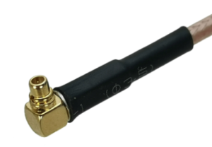
MMCX RA PPS IN/OUT Interface
Applies to the following OPNs: MBF2H516C-CECOT, MBF2H516C-CESOT, MBF2H516C-CEUOT, MBF2M516C-CECOT, MBF2M516C-CESOT, MBF2H536C-CECOT and MBF2H536C-CESOT, MBF2H536C-CEUOT, MBF2H512C-AECOT, MBF2H512C-AESOT, MBF2H512C-AEUOT, MBF2H532C-AECOT, MBF2H532C-AESOT.
The DPU incorporates an integrated Hardware Clock (PHC) that allows the DPU to achieve sub-20u Sec accuracy and also offers many timing-related functions such as time-triggered scheduling or time-based SND accelerations (time-based ASAP²). Furthermore, 5T technology enables the software application to transmit fronthaul (ORAN) at high bandwidth. The PTP part supports the subordinate clock, master clock, and boundary clock.
The DPU PTP solution allows you to run any PTP stack on your host. With respect to testing and measurements, selected NVIDIA DPUs allow you to use the PPS-out signal from the onboard MMCX RA connectors; the DPU also allows measuring PTP in scale, with the PPS-In signal. The PTP HW clock on the DPU will be sampled on each PPS-In signal, and the timestamp will be sent to the SW.Use two MMCX Plug, right-angle, 50ohm cables to connect to the MMCX connectors on the board. See the below example.