Pulse Per Second (PPS)
Pulse Per Second (PPS) is an out-of-band signal used in synchronized systems. 5T technology support PPS-in and PPS-out on selected devices.
PPS-out is a signal generated every time the PHC reaches 1- rounded second. If the device is working in real-time clock mode, the signal triggering is performed fully by the HW and is thus very precise.
Testing Using PPS-out
The signal itself is a square wave. The following figure presents the result on the measurement equipment.
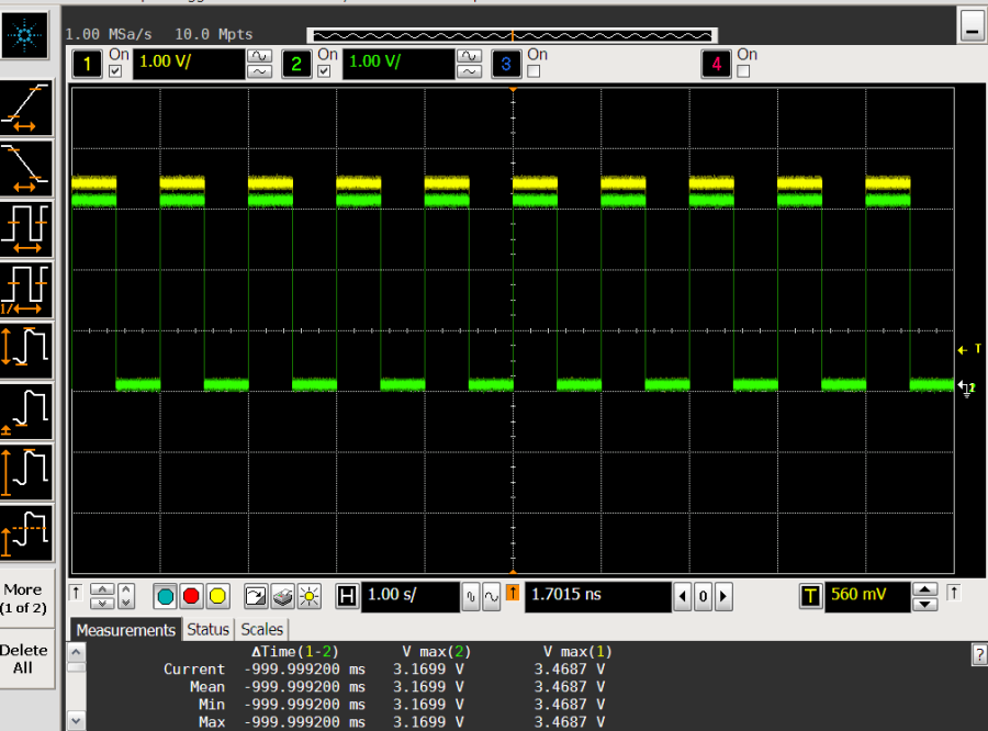
PPS-out on a Scope
The green and yellow signals are generated by two different ConnectX-6 Dx devices and appear to correlate strongly with one another. If the user zooms-in and extends the timescale in the measurement equipment, they should be able to see the Time Alignment Error (TAE) between the devices:
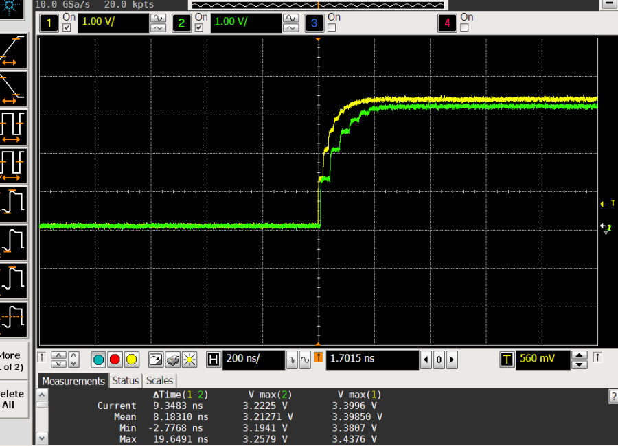
PPS-out Time Alignment Error (TAE) between two synchronized ConnectX-6 Dx devices
PPS-in is a signal that is pushed into the NIC from an external device. This allows the NIC to be synchronized to an external source capable of providing a PPS signal. Examples of such sources include other NIC cards, GNSS receivers or Timecards. Whenever the hardware observes a rising edge on the PPS-in input, it samples the value of the PHC. This value is then reported to software, which can, for example, implement a servo control loop to synchronize the PHC. (For PPS-In testing refer to PPS In events using testptp).
If the NIC is running in real-time clock mode, and the PPS-in is connected to the PPS-out of another PHC device, the TAE (Time Alignment Error) is very low as the following figure illustrates.
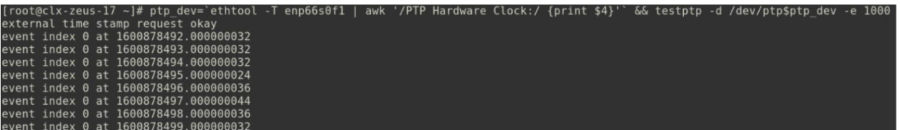
PPS-in Events in Real-time Clock Mode
The following figure very clearly shows that the peak-to-peak time error is 20 nanoseconds, with a constant time error of approximately 33.7 nanoseconds; this assumes that the sampling represents a steady state,
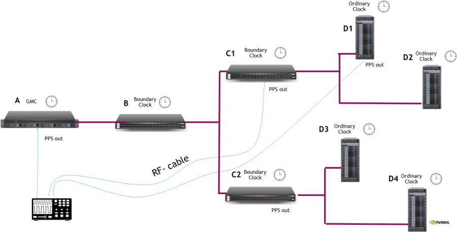
As the following diagram emphasizes, this use case allows using PPS-in as the measurement (instead of the PPS-out) It is now theoretically unlimited by the number of devices that can be tested.
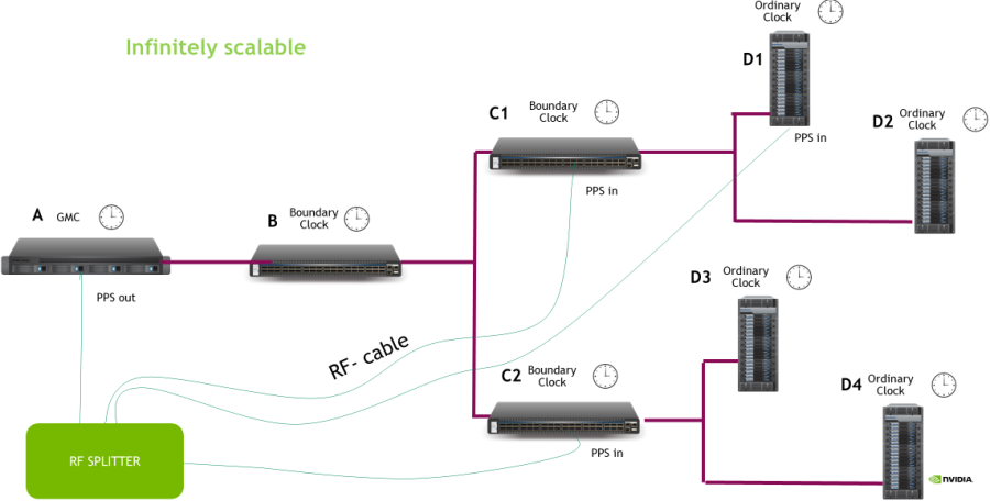
PPS-in for Testing