Testptp
testptp.c is a simple application that can help you test time synchronization features such as One Pulse Per Second (1PPS).
Download the application source code from the following URL: +https://git.kernel.org/pub/scm/linux/kernel/git/torvalds/linux.git/tree/tools/testing/selftests/ptp/testptp.c
Compile the application:
gcc -Wall -lrt testptp.c -o testptp
Install the application:
mv testptp /root/bin/
Configuring PPS In Pin
Set PPS-in on clx-zeus-17:
ptp_dev=`ethtool -T enp66s0f1 | awk
'/PTP Hardware Clock:/ {print $4}'` && testptp -d /dev/ptp$ptp_dev -L0,1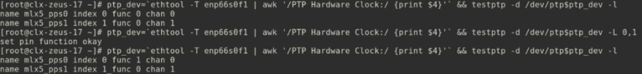
Reading PPS In Events
Set PPS-in read external time stamp events:
ptp_dev=`ethtool -T enp66s0f1 | awk
'/PTP Hardware Clock:/ {print $4}'` && testptp -d /dev/ptp$ptp_dev -e1000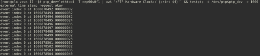
The flag "-e <number>" reads a specified number of external time stamp events. Set <number> to -1 to have testptp read the timestamps infinitely.
Both ts2PHC and testptp, are reading the PPS messages as file descriptor, and cannot run together.
Testptp can still be used for pin configuration, or enabling pps out.
Configuring PPS Out Pin
Confirm REAL_TIME_CLOCK is enabled.
Set PPS-out on clx-zeus-18 (GM).

Generating a Periodic Signal on the PPS Out
Turn PPS-out periodic pulse per 1 sec.

Synchronization with a Generic PPS signal
The ConnectX hardware clock can be synchronized to an external PPS signal. First, connect the source of the PPS signal to the PPS in connector on the bracket. Secondly, run ts2phc:
Introduction
"ts2phc" is an application in linuxptp package.
ts2phc synchronizes PTP Hardware Clocks (PHC) to external time stamp signals. A single source may be used to distribute time to one or more PHC devices.
both ts2PHC and testptp, are reading the PPS messages as file descriptor, and cannot run together.
Testptp can still be used for pin configuration or enabling pps out.
Running ts2phc
Command line:
/root/linuxptp/ts2phc -c /dev/ptp8 -s generic --ts2phc.extts_correction -1 --ts2phc.extts_polarity "rising" --ts2phc.pin_index 0 -l 7 -m
Argument explanation:
Argument | Meaning | Example(s) / Instructions |
-c | Specifies a PHC clock to be synchronized. The clock may be identified by its character device (like /dev/ptp0) or its associated network interface (like eth0). This option may be given multiple times. | dev/ptp8 |
-s | Specifies the source of the PPS signal. Use the key word "generic" for an external 1-PPS without ToD information. When using a master PHC, the clock may be identified by its character device (like /dev/ptp0) or its associated network interface (like eth0). Use the key word "nmea" for an external 1-PPS from a GPS providing ToD information via the RMC NMEA sentence. | generic |
--ts2phc.extts_correction | The value, in nanoseconds, to be added to each PPS time stamp. The default is 0 (no correction). | -1 |
--ts2phc.extts_polarity | The polarity of the external PPS signal, either "rising" or "falling". Some PHC devices always time stamp both edges. Setting this option to "both" will allow the ts2phc program to work with such devices by detecting and ignoring the unwanted edge. In this case be sure to set 'ts2phc.pulsewidth' to the correct value. | Must be : "rising" |
--ts2phc.pin_index | The pin index to be used. Some PHC devices feature programmable pins, and this option allows configuration of a particular pin for the external time stamping or periodic output function. | Must be: 0 |
-l | Sets the maximum syslog level of messages which should be printed or sent to the system logger. The default is 6 (LOG_INFO). | 7 |
-m | Prints log messages to the standard output. | |
-f | Read configuration from the specified file |