Basic Operation and Installation
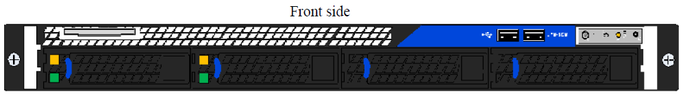
The figure below shows the front and rear sides of the appliance.
The system supports the following:
4 RJ-45 connectors
5 USB connectors
Status LEDs
2 hot-swap power modules
2 hot-swap HDD
System Status LEDs
UFM-SDN Appliance Front and Rear Side Panels

The System Status Indicators are located on the front side panel.
System Status Indicators

|
Legend |
|
|
Label |
Description |
|
A |
System ID Button w/Integrated LED |
|
B |
NIC-1 Activity LED |
|
C |
NIC-2 Activity LED |
|
D |
System Cold Reset Button |
|
E |
System Status LED |
|
F |
Power Button w/Integrated LED |
|
G |
Hard Drive Activity LED |
Appliance Status LED
This is a green and amber

bicolor LED. Two matching activity LEDs are located on each side of the appliance.
|
Status LED Configurations |
|
|
LED Color |
Status |
|
Off |
No power to the appliance. |
|
Solid Green |
OK – the appliance is up and running normally. |
|
Flashing Green (at a rate of 1Hz) |
Noncritical error – the appliance is running yet in a reduced state. Attention required. |
|
Flashing Amber (at a rate of 1Hz) |
Warning – impending critical state. Need to attend to this problem before it becomes fatal. |
|
Amber |
Fatal Error occurred – non-recoverable condition system stopped! |
Power LEDs
UFM-SDN Appliance Front and Rear Side Panels

System Power and On/Off Button and Indicators

The primary power supply unit (PS1) is located on the left side of the rear side panel, with PS2 on the right of the PS1.
Power Supply Unit Status LEDs

Each power supply (PS) unit has a one built-in fan and a single two-color LED on the right side of the PS unit that indicates the internal status of the unit.
The figure "System Power and On/Off Button and Indicators" shows the On/Off switch which contains an integral LED to show the power status of the appliance.
|
PS Unit Status LED Configurations |
|
|
LED Color |
Status |
|
Solid Green |
OK – the Power supply is delivering the correct voltage. |
|
Off |
Off – no power to any of the PS units. |
|
Flashing Green (at a rate of 1Hz) |
PSU off or in cold-redundant state. |
|
Flashing Green (at a rate of 2Hz) |
Firmware is being updated on the PSU. |
|
Flashing Amber (at a rate of 1Hz) |
Power supply warning events where the power supply continues to operate yet with high temp, high power, high current, and slow fan. |
|
Amber |
PS failure (including voltage out of range and power cord disconnected). |
Appliance Identifier ID LED and Button
This appliance has a combination of button and ID LED identification

. The LED can be lit by pushing the button or by using the remote management.
Identification LED and Identifier Button
3.5 Inch Hard Drive LEDs
Hard Drive LEDs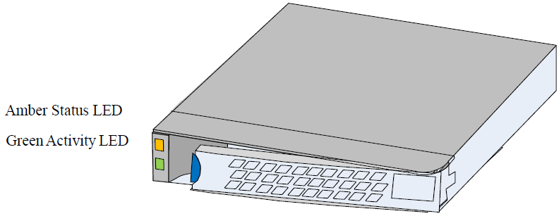
|
Amber |
Off |
No access, no activity |
|
Solid Amber |
A hard drive failure has occurred |
|
|
Flashing Amber |
Redundant Array of Independent Disks (RAID) is being rebuilt. This happens after replacing a faulty drive |
|
Green |
Condition |
Drive Type |
Behavior |
|
Power on with no drive activity |
SAS |
LED stays on |
|
|
SATA |
LED stays off |
||
|
Power on with drive activity |
SAS |
LED blinks off when processing a command |
|
|
SATA |
LED blinks on when processing a command |
||
|
Power on and drive spun down |
SAS |
LED stays off |
|
|
SATA |
LED stays off |
||
|
Power on and drive spinning up |
SAS |
LED blinks |
|
|
SATA |
LED stays off |
Hard Drive Activity LED
This LED indicates activity of the on-board hard disk controllers

. When lit, it indicates activity of the on-board hard disk controllers.
Reset Button
Cold Reset Button
The appliance has a system cold reset button. Pressing this button performs a forced reset of the appliance hardware. For a graceful shutdown of the system (stopping all services, closing all files, flushing all caches etc.) use the relevant CLI command.
NIC Activity LED Indicators
The numbered LEDs display the NICs' activity.
NIC Activity LEDs
|
NIC Activity Indications |
|
|
LED Configuration |
LED Description |
|
Off |
Physical link down / default |
|
Solid Green |
Physical link up with no traffic |
|
Flashing Green |
Physical link up with traffic |
|
Flashing Orange |
Physical errors |
The appliance comes with a single air flow pattern; a front (hard-drive) side to back (power-supply) side.