Anatomy of a Robot Asset Structure#
URDF Overview#
URDF or Universal Robotics Description Format, is an XML-based file convention often used in the robotics world to describe physical aspects of a robot. This is important information for building an accurate simulation, and can be converted to USD for use in Isaac Sim.
Let’s take a look at some of the attributes a URDF can describe, and their USD counterparts.
Links, which are rigid bodies of a robot
Joints, which define relationships between links
Table for comparing USD vs URDF:
USD Joint Name |
URDF Joint Name |
Description |
|---|---|---|
Prismatic |
Prismatic |
Linear joints (ex. elevator) |
Revolute |
Revolute |
Revolute joint with joint limits (ex. Arm joint) |
Continuous |
Revolute joint without joint limits (ex. wheels) |
|
Fixed |
Fixed |
Fixes the robot in place |
D6 |
N/A |
Allow movement in selected DOF. If all are selected, then it is equivalent to a floating joint |
Spherical |
N/A |
Allow movement in x,y,z rotation, equivalent to 3 revolute joints |
Distance |
N/A |
Total freedom until reaches maximum distances between two bodies, Like tying the rope between two bodies |
Gear |
N/A |
Gears |
Rack and Pinion |
N/A |
Rotation converted to translation |
Mimic Joint (attribute) |
Mimic tag |
Allow one joint to follow the specific attribute of another joint. Similar to Gear and Rack and pinion joints but for articulation |
No Joint |
Floating |
No restrictions to the joint. |
N/A |
Planar |
Linear motions along a plane (2 DOF) |
Physical properties such as mass, inertia
Sensors - both type and mount locations
Visual and Collision components
USD Overview#
To use a URDF in Isaac Sim, we need to convert it to USD, or Universal Scene Description. USD is an open and extensible ecosystem for 3D worlds, which Isaac Sim is based around. Let’s review a few important components of USD.
Prim
Prims are fundamental building blocks or elements of a scene within the USD framework. Prim is short for “primitive” and it represents an individual object or entity within the scene hierarchy.
Geometry
A simple pre-defined shape, such as cube, cylinder.
Rigid Body
A mesh that can interact with physics.
Colliders
A mesh used to define the colliders.
Articulation
Creates a tree of rigid bodies and joints to represent the robot structure.
Joints
A mechanism to connect two rigid bodies (As mentioned in URDF section before).
Materials
Layers, References, and Overrides.
You may be seeing some overlap in concepts between these two formats. Thankfully, the conversion process is handled for you with tools inside of Isaac Sim. Let’s use those next.
Asset Structure - Making Module Assets to Suit Multiple Workflows#
In this lecture we’ll show the proposed structure to follow when dealing with a robotics asset.
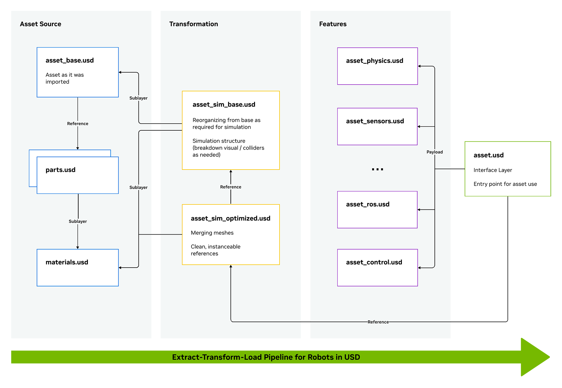
This structure allows the asset to be composed in a modular and non-destructive way, such that each time some component is modified it streamlines towards the final asset to be used, and enables a single point of entry to all different workflows.
Let’s open the gripper asset and inspect its structure. We’ll be using this asset throughout the module.
Open the Asset in Isaac Sim#
To open Isaac Sim, open a terminal run the following command:
~/IsaacSim-main/_build/linux-x86_64/release/isaac-sim.sh --reset-user
Note
If you’re using the pre-built version of Isaac Sim, simply run the isaac-sim.sh --reset-user command from the root of the Isaac Sim installation.
Using File > Open or the Content panel at the bottom of the UI, locate the gripper asset
starting_point/robotiq_2f_140_unoptimized/robotiq_2f_140.usd. This is the “interface layer” of our gripper structure.Double-click the file to open it.
Analyze the available variants#
In the Stage panel on the top right of the UI, select the defaultPrim (
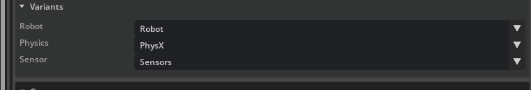
robotiq_arg2f_140_model)In the Property panel, find the Variants section.
Under the Variants section, there are multiple drop downs indicating the feature options you can pick on the asset. If you navigate to the Configuration folder, you’ll see the individual feature assets, along with the base asset.
Visualize Colliders for the Gripper#
Click the “eye” icon and choose Show by Type > Physics > Colliders > All.
Select the gripper or its individual parts to display green outlines indicating collider locations and shapes.
Check how closely the colliders match the visuals, especially inside the gripper fingers.
In the Stage panel, expand the left_inner_finger, and the right_inner_finger by clicking the “+” icon next to their names. You’ll notice that they are not quite equal, and contain multiple meshes inside, which can hurt performance.
Let’s fix that next.