Host State Vector Migration
About this document
The cuStateVec library provides the custatevecSubSVMigrator API to enable users the ability to leverage Host CPU memory in conjunction with device GPU memory to increase the scale of their simulations. This document outlines the possible scenarios for leveraging this API.
custatevecSubSVMigrator API
The custatevecSubSVMigrator API is a utility to migrate state vectors allocated on CPU (host) and additionally on GPU (device). This API allows utilizing CPU memory to accommodate state vector. One can also utilize both CPU and GPU memory to allocate a single state vector to maximize the number of qubits to be simulated.
Memory model of custatevecSubSVMigrator API
The custatevecSubSVMigrator API assumes the memory model shown in Figure 1. A state vector is assumed to be equally sliced to a series of sub state vectors. The number of sub state vectors should always be a power-of-two. Each sub state vector can be placed on a host or device slot.
A sub state vector represents a partial state and has local index bits which corresponds to a subset of qubits. Its size is \(2^{nLocalIndexBits}\) where nLocalIndexBits is the number of local index bits.
There is one requirement, that host slots should be directly accessible from the device. This means cudaHostAlloc() would be used to allocate CUDA pinned memory on x86 platform without HMM. For other systems such as GH200, memory chunks allocated by using malloc() are accessible from the device, thus, allocating CUDA pinned memory is not mandatory. Each host slot can have its own memory chunk or can be allocated as a single contiguous memory chunk. It’s a developer’s choice.
Device slots should be allocated as a single device memory chunk where all device slots are contiguously placed. This allows utilizing device slots as a single chunk of a partial state vector. With this configuration, operations, such as gate applications, for device slot index bits are applied in device slots. Therefore, the number of device slots is always a power-of-two number.
In the cuStateVec library, this model is expressed by custatevecSubSVMigratorDescriptor_t which is created by custatevecSubSVMigratorCreate() and destroyed by custatevecSubSVMigratorDestroy().
Index bit swap is the algorithm to localize index bits in cuStateVec as described in Qubit reordering and distributed index bit swap for distributed index bit swap API documentation. When migrating sub state vectors, index bits are swapped by using custatevecSubSVMigrator API and custatevecSwapIndexBits() as described in later sections in this document.
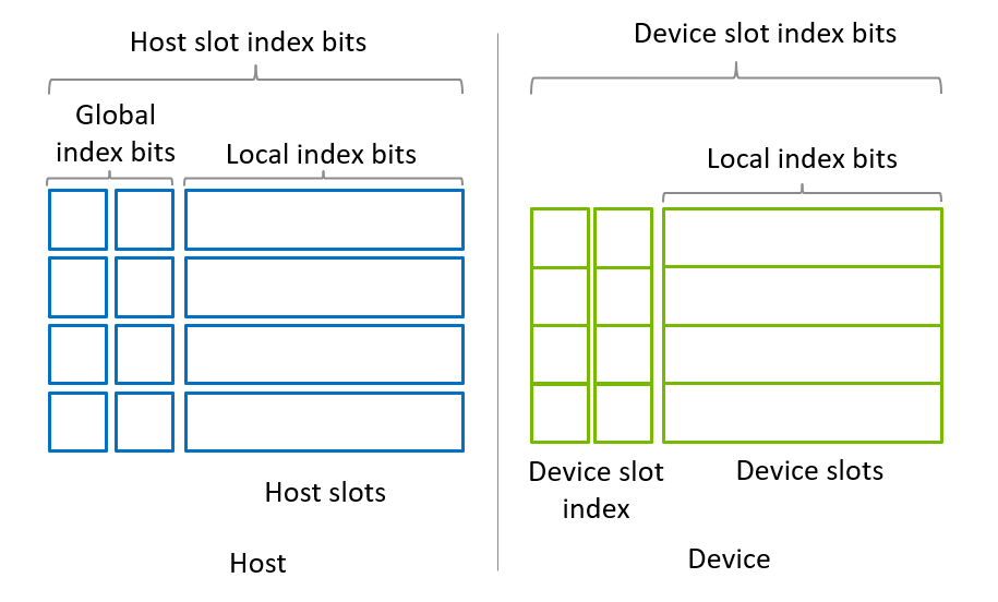
Figure 1. Memory model of SubStateVectorMigrator API
Possible scenarios
There are two scenarios wherein one might allocate a state vector by using host memory.
Allocate state vector on host
If the amount of host memory is large enough to hold the entire state vector, one is able to allocate the state vector on host slots and use device slots to apply operations. During simulations, sub state vectors are copied to device slots (checkout), and after operations applied, state vectors are copied back to the host slots (check-in). This migration step is iterated for operations to be applied for all sub state vectors.
Allocate state vector on both host and device
In order to utilize host and device memory as much as possible (in order to allocate the largest state vector), one is able to use both host and device memory to allocate the state vector. Operations are applied on device, and sub state vectors are swapped between host and device to apply operations for all sub state vectors.
1. Allocate state vector on host slots
Figure 2 shows a simplified example of a sub state vector allocated on host slots. Four sub state vectors are placed on host slots, and two device slots are allocated and kept empty. There are two global index bits which are denoted as p and q.
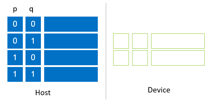
Figure 2. State vector allocated on host slots
When using NVIDIA H100 (80G) and allocating memory to device slots as shown in Figure 2, the size of device slots is 64 GB, and the size of each slot is 32 GB. The host state vector size is twice as large, thus, the size of host state vector is 128 GB. The max state vector size with NVIDIA H100 (80G) is 33 qubits (c64) and 32 qubits (c128), respectively. By using 128 GB of host memory, the maximum state vector size increases by 1, reaching to 34 (complex64) and 33 (complex128) qubits, respectively.
With the SubStateVectorMigrator API, sub state vectors migrate by using the following primitives. By combining these primitives, global and local index bits are appropriately reordered.
Checkout a sub state vector in a host slot to a device slot.
Copy host sub state vector on a host slot to a device slot. This operation is executed by passing a host slot pointer to the srcSubSV argument of
custatevecSubSVMigratorMigrate().
Check-in a sub state vector on a device slot to a host slot.
Copy back a device slot to a host slot. This operation is executed by passing a host slot pointer to the dstSubSV argument of
custatevecSubSVMigratorMigrate().
Swap index bits in device slots
Move local index bits to global index bit positions. This operation is executed by using the
custatevecSwapIndexBits()API.
Global index bits are moved as shown in Figure 3. Figure 3 (a-1) shows the first migration to localize a global index bit, q. The 0th and 1st sub state vectors are copied to device slots (checkout), and q moves to the device slot index bit. Then, gate applications and other operations are applied for the device slots for device slot index bits that contains q and local index bits. After operations complete, device slots are copied back to update the host slots (Figure 3 (a-2)), which updates the first half of the state vector (check-in). The same sequence of steps is executed for the second half of the state vector (Figure 3 (a-3, 4)).
In order to move a global index bit, p, to device slots, 0th and 2nd sub state vectors are copied to device slots, which moves p to the device slot index bit (Figure 3 (b-1)). Similar steps shown in Figure 3 (b-2) - (b-4) are applied to complete operations.
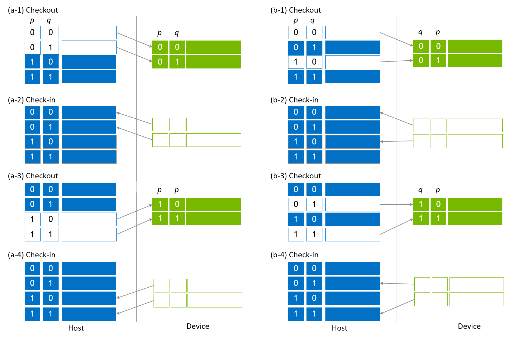
Figure 3. Host vector migration to localize global index bits
There is an optimization during state vector migration to overlap checkout and check-in sub state vectors to utilize bidirectional transfer (on PCIe on x86 systems and on NVLink-C2C on GH200) between host and device. The left part of Figure 4 is a cut-out of Figure 3 (a-2) and (a-3). These two steps are fused to a single step as shown in the right part of Figure 4.
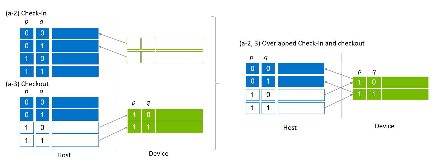
Figure 4. Overlapped check-in and checkout
In order to swap local index bits to global index bits, index bit swap is applied during migration steps as shown in Figure 5. The left part of the figure shows the initial state vector allocation where p and q are global index bits, and r denotes the LSB of local index bits being swapped with a global index bit, q.
The fist checkout step is identical to the migration step shown in Figure 3. Then, q and r are swapped to move q to be a local index bit and r to be a global index bit. This swap is operated by a cuStateVec API, custatevecSwapIndexBits(). After swapping q and r, sub state vectors on device slots are checked in to the host slots. By applying the same for the rest of host sub state vectors, a global index bit, q and a local index bit, r, are swapped.
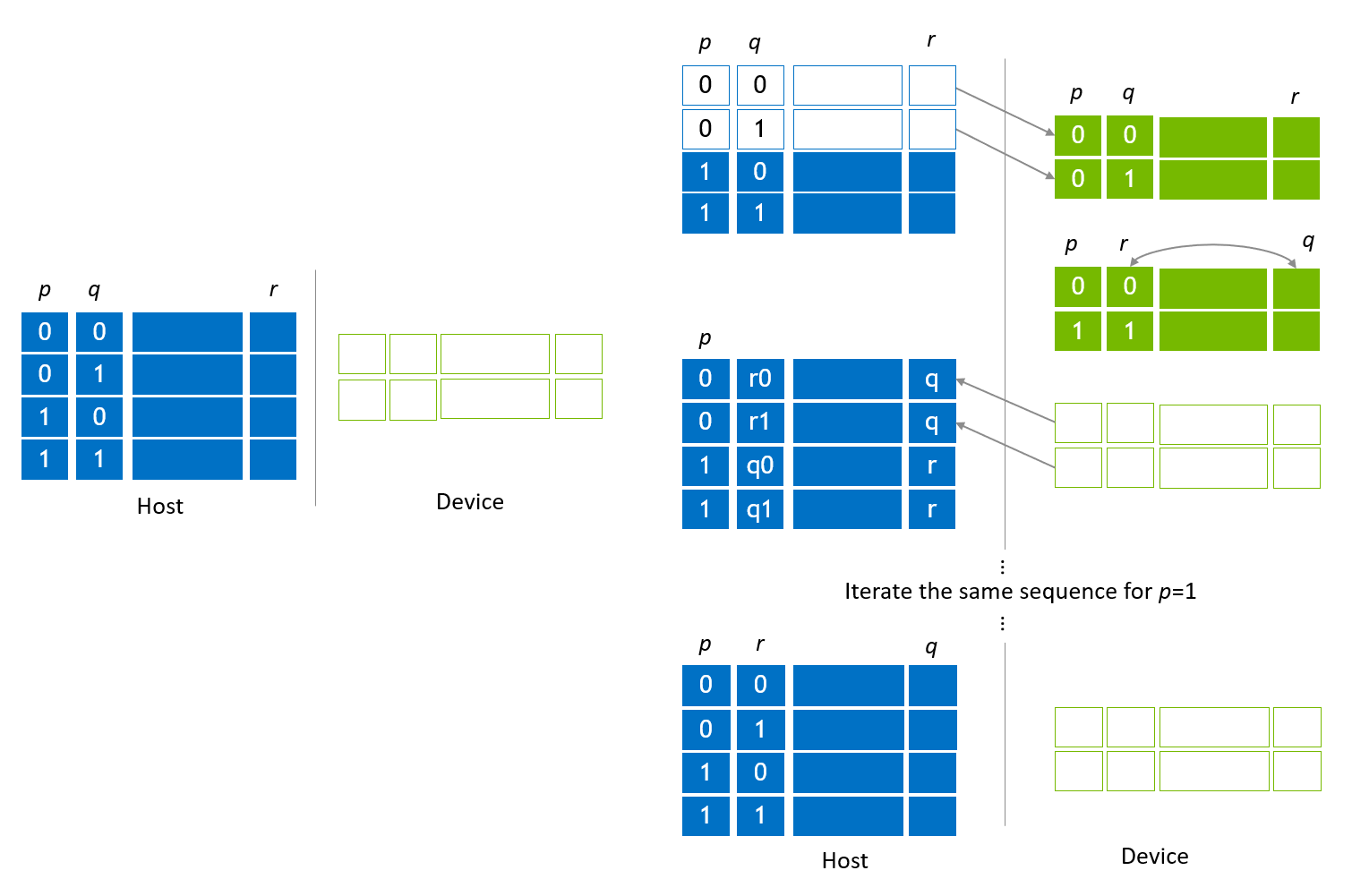
Figure 5. Index bit swap of global and local index bits
2. Allocate state vector on host and device slots
The second scenario is to utilize host and device memory and allocate the state vector on them to maximize the size of the state vector. An example allocation is shown in Figure 6, which is the simplest case that has two sub state vectors placed in each host and device slot. This example is used to describe the migration algorithm for simplicity. By increasing the number of sub state vectors on host, one is able to allocate larger state vectors.
Ex. When NVIDIA H100 (80G) is employed to allocate device slots according to Figure 6, the max size of device slots is 64 GB. The host state vector size is identical, thus, the size of host state vector is 128 GB (64 GB on host + 64 GB on device). By using 448 GB host memory, the state vector size grows to 512 GB.
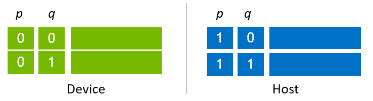
Figure 6. State vector allocated on host and device
For the state vector allocated on host and device, the primitive of state vector migration is swap, which is considered as an overlapped check-in and checkout to the same host state vector. custatevecSubSVMigrator swaps sub state vectors by passing the same host sub state vector pointer to srcSubSV and dstSubSV arguments of custatevecSubSVMigratorMigrate().
State vector migration is executed as illustrated in Figure 7. The first step shown in Figure 7 (a) is the initial state where a global index bit, q is localized in device slots. In Figure 7 (b),operations are applied for device slot index bits that contains a global index bit q and local index bits. Then, sub state vectors are swapped between host and device, and operations are applied for the second half of the state vector (Figure 7 (c), (d)).
The next migration sequence is aiming at localizing a global index bit, p, and applying operations. The first migration is to swap the 0th device sub state vector and the 1st host sub state vector (Figure 7 (e)). Then, the operations are applied (Figure 7 (f)) for the first half of the state vector. The next migration is to swap sub state vectors between host and device, and operations are applied for the second half of the state vector.
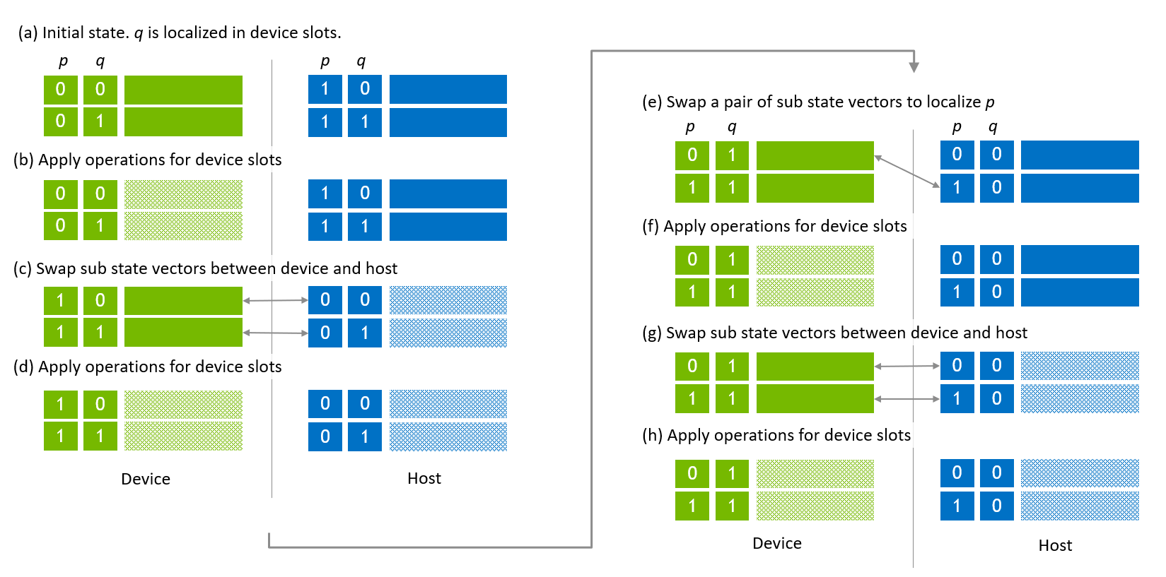
Figure 7. State vector migration of host-device state vector
In order to swap a global index bit and a local index bit, the cuStateVec API, custatevecSwapIndexBits() is applied in the same way as used for host state vector. Figure 8 (a) shows the same placement of host and device sub state vectors where p and q are global index bits and r is the LSB of local index bits. After applying operations (Figure 8 (b)), q and r are swapped (Figure 8 (c)). Then, sub state vectors are swapped between host and device (Figure 8 (d)). Executing the same steps for the remaining sub state vectors, q and r are swapped (Figure 8 (e)).
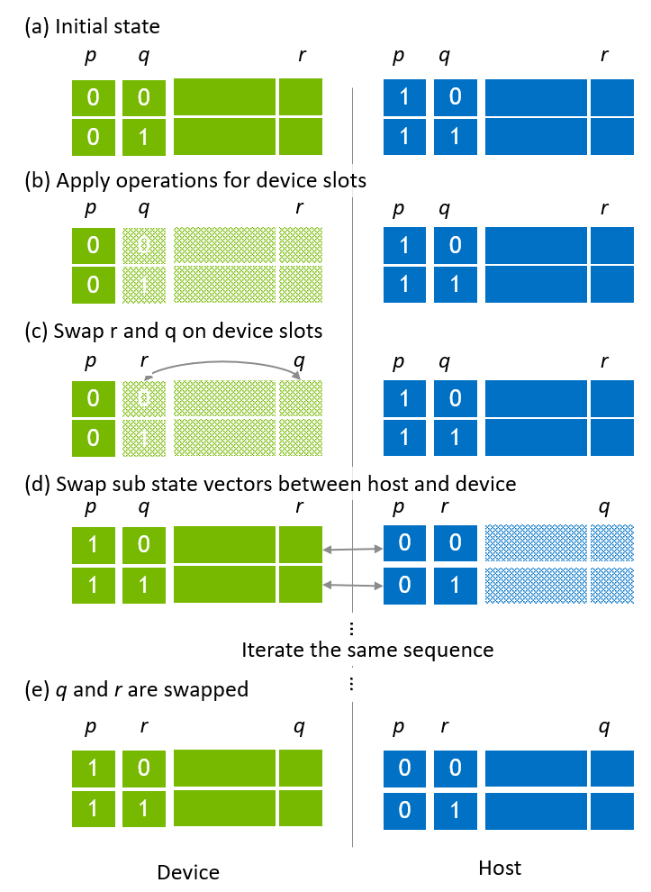
Figure 8. Swapping global and local index bits in host-device state vector