Vendor-Specific Extensions#
This section describes cuBB vendor-specific extensions to the 5G FAPI 222.10.02 specification. These extensions enable advanced features and performance optimizations beyond the standard specification.
SLOT.response Message#
Overview#
L2 must send the SLOT.response FAPI message as the last FAPI message for each cell in each slot. This message serves as the “End of Message” (EOM) marker for each cell, signaling that all FAPI messages for that slot have been sent.
Message Format#
The SLOT.response message format is shown below:
typedef struct
{
  scf_fapi_body_header_t msg_hdr;
  uint16_t sfn;
  uint16_t slot;
} __attribute__ ((__packed__)) scf_fapi_slot_rsp_t;

Message ID: 0x8F (SCF_FAPI_SLOT_RESPONSE)
Implementation Requirements#
When implementing SLOT.response, the following requirements apply:
L2 must send the
SLOT.responsemessage as the last FAPI message for each cell in each slot.L2 must send this message even in empty slots (where nothing is scheduled).
L2 must complete sending all FAPI messages within the 500 us time-budget marked by
SLOT.indicationfrom L1.Late FAPI messages will be dropped.
A “Dummy” DL/UL TTI message in empty slots is optional.
A notify event from L2 after sending all FAPI messages is optional.
L1 will continue to send a notify event after all FAPI messages to L2 to minimize impact on L2.
Message Sequence#
An example message sequence is shown below:
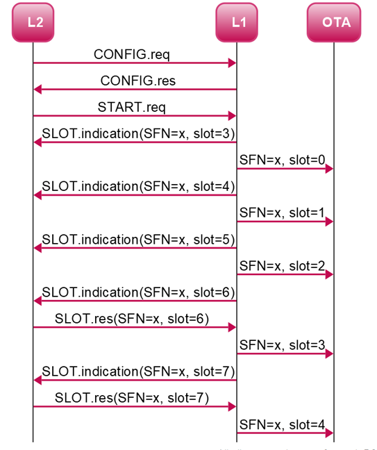
Note
On receiving the first SLOT.indication, L2 is unable to send SLOT.response for 2-3 slots because it has a slot advance of 3.
Message Timing Behavior#
A message is considered late if it is not received within the 500 us time-budget from the SLOT.indication message sent by L1.
SLOT.response Not Received:
If
SLOT.responseis not received for a cell, all FAPI messages received in time will still be processed for that cell.
Late Message Scenarios:
All messages late for a cell (DL_TTI+TX_DATA+UL_DCI or UL_TTI): All messages are dropped for the affected cell. Other cells are not impacted.
Partial slot (DL_TTI on time but TX_DATA.request is late): Due to cell grouping, PDSCH and DL-PDCCH are dropped for all cells.
UL_TTI late: ULSCH is not processed for the affected cell. Other cells are not impacted.
UL_DCI late: UL-PDCCH is not processed for the affected cell. Other cells are not impacted.
64T64R Beamforming Support#
This section describes vendor-specific extensions for 64T64R beamforming support, including both dynamic and static beamforming capabilities.
Dynamic Beamforming for 64T64R#
Overview#
Dynamic beamforming enables L1 to calculate beamforming weights for downlink and uplink transmissions based on SRS channel estimates. This feature is supported for PDSCH and PUSCH channels.
Message Format#
Two new vendor-specific FAPI messages are defined from L2 to L1 to request beamforming weight calculation:
SCF_FAPI_DL_BFW_CVI_REQUEST (Message ID: 0x90)
SCF_FAPI_UL_BFW_CVI_REQUEST (Message ID: 0x91)
The same message structure is used for both DL (PDSCH) and UL (PUSCH). When used for DL (PDSCH), it is referred to as DLBFW_CVI.request and when used for UL (PUSCH), it is referred to as ULBFW_CVI.request. These messages will be enabled through the compilation flag SCF_FAPI_10_04.
DLBFW_CVI.request message body
Field |
Type |
Description |
|---|---|---|
SFN |
uint16_t |
SFN Value: 0 -> 1023 |
Slot |
uint16_t |
Slot Value: 0 -> 159 |
nPDUs |
uint8_t |
Number of PDUs that are included in this message. All PDUs in the message are numbered in order. Value: 0 -> 255 |
For Number of PDUs { |
||
PDUSize |
uint16_t |
Size of the PDU control information (in bytes). This length value includes the 4 bytes required for the PDU type and PDU size parameters. Value: 0 -> 65535 |
DLBFW CVI Configuration |
structure |
See DLBFW CVI PDU table below |
} |
||
DLBFW CVI PDU
Field |
Type |
Description |
|---|---|---|
rbStart |
uint16_t |
For resource allocation type 1 [TS38.214, sec 5.1.2.2] The starting resource block within the BWP for this PDSCH. Value: 0 -> 274 |
rbSize |
uint16_t |
For resource allocation type 1 [TS38.214, sec 5.1.2.2] The number of resource block within for this PDSCH. Value: 1 -> 275 |
numPRBs |
uint16_t |
Number of PRBs spanning this allocation. Value: 1 -> 275 |
prgSize |
uint16_t |
Size in RBs of a precoding resource block group (PRG) - to which same precoding and digital beamforming gets applied. Value: 1 -> 275 |
nUe |
uint8_t |
Number of UE in this group Value: 1 -> 18 |
For Number of UEs { |
||
Handle |
uint32_t |
0 to 7 bits => For future use 8 to 23 bits => Buffer index of SRS Channel estimates stored in device memory. 24 to 31 bits => For future use |
RNTI |
uint16_t |
The RNTI used for identifying the UE when receiving the PDU Value: 1 -> 65535 |
pduIndex |
uint16_t |
PDU index associated to pduIndex in PDSCH PDU of DL_TTI request Value: 0 -> 65535 |
nSCID |
uint8_t |
DMRS sequence initialization [3GPP TS 38.211 [2], sec 7.4.1.1.2]. as provided by parameter nSCID For example, in reference [2], this value is associated with DMRS scrambling ID given by dlDmrsScramblingId Value: 0 -> 1 |
dmrsPorts |
uint16_t |
DMRS ports: [3GPP TS 38.212 [3], 7.3.1.2.2] provides description between DCI 1-1 content and DMRS ports. Bitmap occupying the 12 LSBs with: bit 0: antenna port 1000 bit 11: antenna port 1011 and for each bit 0: DMRS port not used 1: DMRS port used |
gnbAntIdxStart |
uint8_t |
Corresponding to “gI” indicated by “Array representing channel matrix H” in SRS.indication. L1 can regard antenna indices from “gnbAntIdxStart” to “gnbAntIdxEnd” are used. Value: 0 |
gnbAntIdxEnd |
uint8_t |
Corresponding to “gI” indicated by “Array representing channel matrix H” in SRS.indication. L1 can regard antenna indices from “gnbAntIdxStart” to “gnbAntIdxEnd” are used. Value: 63 |
numOfUeAnt |
uint8_t |
Value: 1->4 |
For number of UE Ants { |
||
ueAntIdx |
uint8_t |
Corresponding to “uI” indicated by “Array representing channel matrix H” in SRS.indication. Value: 0,1,2,3 |
} |
||
} |
||
Implementation Requirements#
Required TLVs
The following vendor-specific TLVs are required in CONFIG.req for dynamic beamforming:
TLV 0xA016: NUM_TX_PORT (uint8_t) - Specifies the number of DL BB ports for PHY
TLV 0xA017: NUM_RX_PORT (uint8_t) - Specifies the number of UL BB ports for PHY
TLV 0xA019: NUM_SRS_CHEST_BUFFERS (uint32_t) - Configures the number of SRS channel estimate buffers per cell
Refer to Vendor-Specific TLVs for complete field details.
SRS Buffer Indexing
L2 must manage SRS channel estimate buffer indexing as follows:
L1 pre-allocates
total_num_srs_chest_buffersbuffers (configurable via cuphycontroller_xxx.yaml, maximum: 6144) to store SRS Channel Estimates across all cells.L2 configures the number of SRS channel estimate buffers per cell using TLV 0xA019 (up to 1024 buffers, indexes 0-1023).
L2 manages buffer indexes across all active UEs.
L2 specifies the buffer index in the
handlefield of UL_TTI SRS PDU (see SRS PDU).L1 returns the same buffer index in the corresponding SRS.IND
handlefield.L2 specifies the SRS buffer index in the
handlefield of DLBFW_CVI.request/ULBFW_CVI.request for beamforming weight calculation.Error indication is reported if L2 reuses a buffer index before receiving the corresponding SRS.INDICATION.
Request is dropped if L2 references a buffer index in DLBFW_CVI.request/ULBFW_CVI.request before SRS.INDICATION is sent.
Additional Requirements
DL & UL TTI have an additional field added for TRP scheme which needs to be set to 0 for dynamic beamforming.
Static Beamforming for 64T64R#
TLV 0xA010 DIGITAL_BEAM_TABLE_PDU (uint8_t) is required in CONFIG.request to encode the Digital Beam Table (DBT) PDU containing static beamforming weights for specific channels. See Vendor-Specific TLVs for details.
Static beamforming weights are defined per FAPI 222.10.04 Table 3-61 Digital Beam Table (DBT) PDU. See Digital Beam Table (DBT) PDU for details.
L2 must use NVIPC buffer pool
cpu_largeto encode and transmit the DBT PDU.
UL TTI Bundling#
TLV 0xA10A PUSCH_AGGR_FACTOR (uint8_t) configures the maximum number of UL TTIs that can be bundled together in multi-slot ULSCH procedure. See Vendor-Specific TLVs for details.
L2 indicates a multi-slot ULSCH PDU by setting the 4th bit in the
pduBitmapfield of the PUSCH PDU within the UL_TTI.request message.