SDK Development Guide
Welcome to the Holoscan SDK development guide! Here you will learn the core concepts behind Holoscan, where we will first explore the Entity-Component-System pattern, and how it is used when building Holoscan extensions and apps.
Holoscan applications are built as compute graphs, based on GXF. This design provides modularity at the application level since existing entities can be swapped or updated without needing to recompile any extensions or application.
Those are the key terms used throughout this guide:
Each node in the graph is known as an entity
Each edge in the graph is known as a connection
Each entity is a collection of components
Each component performs a specific set of subtasks in that entity
The implementation of a component’s task is known as a codelet
Codelets are grouped in extensions
Similarly, the componentization of the entity itself allows for even more isolated changes. For example, if in an entity we have an input, an output, and a compute component, we can update the the compute component without changing the input and output.
Holoscan Entities by Example
Let us look at an example of a Holoscan entity to try to understand its general anatomy. As an example let’s start with the entity definition for an image format converter entity named format_converter_entity as shown below.
            %YAML 1.2
---
# other entities declared
---
name: format_converter_entity
components:
  - name: in_tensor
    type: nvidia::gxf::DoubleBufferReceiver
  - type: nvidia::gxf::MessageAvailableSchedulingTerm
    parameters:
      receiver: in_tensor
      min_size: 1
  - name: out_tensor
    type: nvidia::gxf::DoubleBufferTransmitter
  - type: nvidia::gxf::DownstreamReceptiveSchedulingTerm
    parameters:
      transmitter: out_tensor
      min_size: 1
  - name: pool
    type: nvidia::gxf::BlockMemoryPool
    parameters:
      storage_type: 1
      block_size: 4919040 # 854 * 480 * 3 (channel) * 4 (bytes per pixel)
      num_blocks: 2
  - name: format_converter_component
    type: nvidia::holoscan::formatconverter::FormatConverter
    parameters:
      in: in_tensor
      out: out_tensor
      out_tensor_name: source_video
      out_dtype: "float32"
      scale_min: 0.0
      scale_max: 255.0
      pool: pool
---
# other entities declared
---
components:
  - name: input_connection
    type: nvidia::gxf::Connection
    parameters:
      source: upstream_entity/output
      target: format_converter/in_tensor
---
components:
  - name: output_connection
    type: nvidia::gxf::Connection
    parameters:
      source: format_converter/out_tensor
      target: downstream_entity/input
---
name: scheduler
components:
  - type: nvidia::gxf::GreedyScheduler
Above:
The entity
format_converter_entityreceives a message in itsin_tensormessage from an upstream entityupstream_entityas declared in theinput_connection.The received message is passed to the
format_converter_componentcomponent to convert the tensor element precision fromuint8tofloat32and scale any input in the[0, 255]intensity range.The
format_converter_componentcomponent finally places the result in theout_tensormessage so that its result is made available to a downstream entity (downstream_entas declared inoutput_connection).The
Connectioncomponents tie the inputs and outputs of various components together, in the above caseupstream_entity/output -> format_converter_entity/in_tensorandformat_converter_entity/out_tensor -> downstream_entity/input.The
schedulerentity declares aGreedyScheduler“system component” which orchestrates the execution of the entities declared in the graph. In the specific case ofGreedySchedulerentities are scheduled to run exclusively, where no more than one entity can run at any given time.
The YAML snippet above can be visually represented as follows.
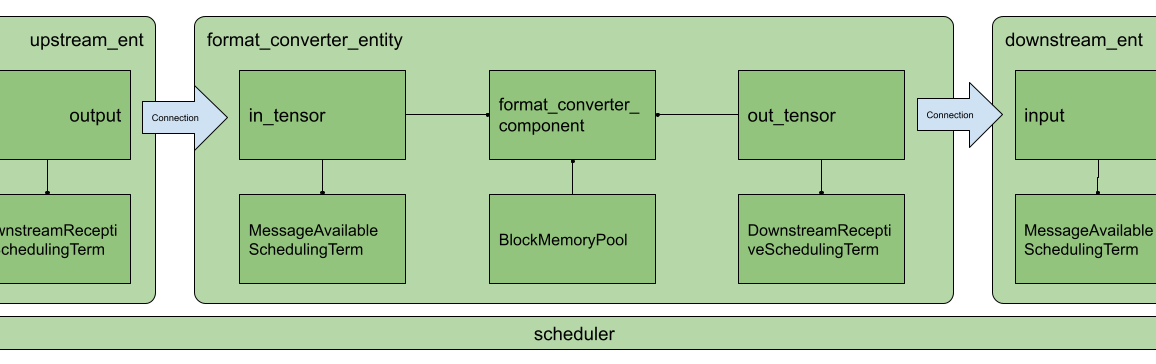
Fig. 7 Arrangement of components and entities in a Holoscan application
In the image, as in the YAML, you will notice the use of MessageAvailableSchedulingTerm, DownstreamReceptiveSchedulingTerm, and BlockMemoryPool. These are components which play a “supporting” role to in_tensor, out_tensor, and format_converter_component components respectively. Specifically:
MessageAvailableSchedulingTermis a component which takes aReceiver(in this caseDoubleBufferReceivernamedin_tensor) and alerts the graphExecutorthat a message is available. This alert triggersformat_converter_component.DownstreamReceptiveSchedulingTermis a component which takes aTransmitter(in this caseDoubleBufferTransmitternamedout_tensor) and alerts the graphExecutorthat a message has been placed on the output.BlockMemoryPoolprovides two blocks of almost5MBallocated on the GPU device, and is used byformat_converted_entto allocate the output tensor where the converted data will be placed within the format converted component.
Together these components allow the entity to perform a specific function and coordinate communication with other entities in the graph via the declared scheduler.
More generally, an entity can be thought of as a collection of components where components can be passed to one another to perform specific subtasks (e.g. event triggering or message notification, format conversion, memory allocation), and an application as a graph of entities.
The scheduler is a component of type nvidia::gxf::System which orchestrates the execution components in each entity at application runtime based on triggering rules.
Data Flow and Triggering Rules
Entities communicate with one another via messages which may contain one or more payloads. Messages are passed and received via a component of type nvidia::gxf::Queue from which both nvidia::gxf::Receiver and nvidia::gxf::Transmitter are derived. Every entity that receives and transmits messages has at least one receiver and one transmitter queue.
Holoscan uses the nvidia::gxf::SchedulingTerm component to coordinate data access and component orchestration for a Scheduler which invokes execution through the tick() function in each Codelet.
A SchedulingTerm defines a specific condition that is used by an entity to let the scheduler know when it’s ready for execution.
In the above example we used a MessageAvailableSchedulingTerm to trigger the execution of the components waiting for data from in_tensor receiver queue, namely format_converter_component.
              - type: nvidia::gxf::MessageAvailableSchedulingTerm
    parameters:
      receiver: in_tensor
      min_size: 1
Similarly DownStreamReceptiveSchedulingTerm checks whether the out_tensor transmitter queue has at least one outgoing message in it. If there is one or more outgoing messages, DownStreamReceptiveSchedulingTerm will notify the scheduler which in turn attempts to place the message in the receiver queue of a downstream entity. If the downstream entity, however, has a full receiver queue the message is held in the out_tensor queue as a means to handle back-pressure.
              - type: nvidia::gxf::DownstreamReceptiveSchedulingTerm
    parameters:
      transmitter: out_tensor
      min_size: 1
If we were to draw the entity in Fig. 7 in greater detail it would look something like the following.
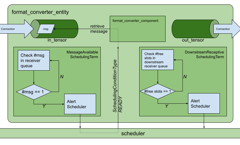
Fig. 8 Receive and transmit
Queues and
SchedulingTerms in entities.
Up to this point we have covered the “entity component system” at a high level and showed the functional parts of an entity, namely, the messaging queues and the scheduling terms that support the execution of components in the entity. To complete the picture, the next section covers the anatomy and lifecycle of a component, and how to handle events within it.
Components in Holoscan can perform a multitude of sub-tasks ranging from data transformations, to memory management, to entity scheduling. In this section we will explore an nvidia::gxf::Codelet component which in Holoscan is known as an “extension”. Holoscan extensions are typically concerned with application-specific sub-tasks such as data transformations, AI model inference, and the like.
Extension Lifecycle
The lifecycle of a Codelet is composed of the following five stages.
initialize- called only once when the codelet is created for the first time, and use of light-weight initialization.deinitialize- called only once before the codelet is destroyed, and used for light-weight de-initialiation.start- called multiple times over the lifecycle of the codelet according to the order defined in the lifecycle, and used for heavy initialization tasks such as allocating memory resources.stop- called multiple times over the lifecycle of the codelet according to the order defined in the lifecycle, and used for heavy deinitialization tasks such as deallocation of all resources previously assigned instart.tick- called when the codelet is triggered, and is called multiple times over the codelet lifecycle; even multiple times betweenstartandstop.
The flow between these stages is detailed in Fig. 9.
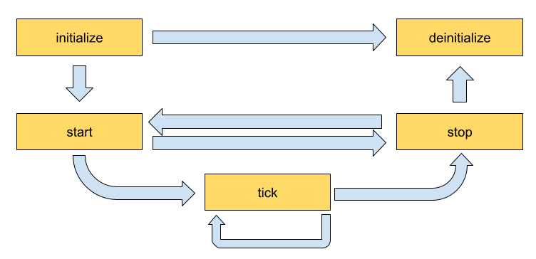
Fig. 9 Sequence of method calls in the lifecycle of a Holoscan extension
Implementing an Extension
In this section we will implement a simple recorder which will highlight the actions we would perform in the lifecycle methods. The recorder receives data in the input queue and records the data to a configured location on the disk. The output format of the recorder files is the GXF-formatted index/binary replayer files (the format is also used for the data in the sample applications).
Declare the Class That Will Implement the Extension Functionality
The developer can create their Holoscan extension by extending the Codelet class, implementing the extension functionality by overriding the lifecycle methods, and defining the parameters the extension exposes at the application level via the registerInterface method. To define our recorder component we would need to implement some of the methods in the Codelet as follows.
            class MyRecorder : public nvidia::gxf::Codelet {
 public:
  gxf_result_t registerInterface(nvidia::gxf::Registrar* registrar) override;
  gxf_result_t initialize() override;
  gxf_result_t deinitialize() override;

  gxf_result_t start() override;
  gxf_result_t tick() override;
  gxf_result_t stop() override;

 private:
  nvidia::gxf::Parameter<nvidia::gxf::Handle<nvidia::gxf::Receiver>> receiver_;
  nvidia::gxf::Parameter<nvidia::gxf::Handle<nvidia::gxf::EntitySerializer>> my_serializer_;
  nvidia::gxf::Parameter<std::string> directory_;
  nvidia::gxf::Parameter<std::string> basename_;

  // File stream for data index
  nvidia::gxf::FileStream index_file_stream_;
  // File stream for binary data
  nvidia::gxf::FileStream binary_file_stream_;
  // Offset into binary file
  size_t binary_file_offset_;
};
Declare the Parameters to Expose at the Application Level
Our recorder will need to expose the nvidia::gxf::Parameter variables to the application so the parameters can be modified by configuration.
            gxf_result_t MyRecorder::registerInterface(nvidia::gxf::Registrar* registrar) override {
  nvidia::gxf::Expected<void> result;
  result &= registrar->parameter(
      receiver_, "receiver", "Entity receiver",
      "Receiver channel to log");
  result &= registrar->parameter(
      my_serializer_, "serializer", "Entity serializer",
      "Serializer for serializing input data");
  result &= registrar->parameter(
      directory_, "out_directory", "Output directory path",
      "Directory path to store received output");
  result &= registrar->parameter(
      basename_, "basename", "File base name",
      "User specified file name without extension",
      nvidia::gxf::Registrar::NoDefaultParameter(), GXF_PARAMETER_FLAGS_OPTIONAL);
  result &= registrar->parameter(
      flush_on_tick_, "flush_on_tick", "Boolean to flush on tick",
      "Flushes output buffer on every `tick` when true", false);  // default value `false`
  return nvidia::gxf::ToResultCode(result);
}
In the application YAML, our component’s parameters can be specified as follows.
            name: my_recorder_entity
components:
  - name: my_recorder_component
    type: MyRecorder
    parameters:
      receiver: receiver
      serializer: my_serializer
      out_directory: /home/user/out_path
      basename: my_output_file  # optional
      # flush_on_tick: false # optional
Note that all the parameters exposed at the application level are mandatory except for flush_on_tick, which defaults to false, and basename, whose default is handled at initialize() below.
Implement the Lifecycle Methods
This extension does not need to perform any heavy-weight initialization tasks, so we will concentrate on initialize(), tick(), and deinitialize() methods which define the core functionality of our component. At initialization, we will create a file stream and keep track of the bytes we write on tick() via binary_file_offset.
            gxf_result_t MyRecorder::initialize() {
  // Create path by appending receiver name to directory path if basename is not provided
  std::string path = directory_.get() + '/';
  if (const auto& basename = basename_.try_get()) {
    path += basename.value();
  } else {
    path += receiver_->name();
  }

  // Initialize index file stream as write-only
  index_file_stream_ = nvidia::gxf::FileStream("", path + nvidia::gxf::FileStream::kIndexFileExtension);

  // Initialize binary file stream as write-only
  binary_file_stream_ = nvidia::gxf::FileStream("", path + nvidia::gxf::FileStream::kBinaryFileExtension);

  // Open index file stream
  nvidia::gxf::Expected<void> result = index_file_stream_.open();
  if (!result) {
    return nvidia::gxf::ToResultCode(result);
  }

  // Open binary file stream
  result = binary_file_stream_.open();
  if (!result) {
    return nvidia::gxf::ToResultCode(result);
  }
  binary_file_offset_ = 0;

  return GXF_SUCCESS;
}
When de-initializing, our component will take care of closing the file streams that were created at initialization.
            gxf_result_t MyRecorder::deinitialize() {
  // Close binary file stream
  nvidia::gxf::Expected<void> result = binary_file_stream_.close();
  if (!result) {
    return nvidia::gxf::ToResultCode(result);
  }

  // Close index file stream
  result = index_file_stream_.close();
  if (!result) {
    return nvidia::gxf::ToResultCode(result);
  }

  return GXF_SUCCESS;
}
In our recorder, no heavy-weight initialization tasks are required so we implement the following, however, we would use start() and stop() methods for heavy-weight tasks such as memory allocation and deallocation.
            gxf_result_t MyRecorder::start() {
  return GXF_SUCCESS;
}

gxf_result_t MyRecorder::stop() {
  return GXF_SUCCESS;
}
For a detailed implementation of start() and stop(), and how memory management can be handled therein, please refer to the implementation of the AJA Video source extension.
Finally, we write the component-specific functionality of our extension by implementing tick().
            gxf_result_t MyRecorder::tick() {
  // Receive entity
  nvidia::gxf::Expected<nvidia::gxf::Entity> entity = receiver_->receive();
  if (!entity) {
    return nvidia::gxf::ToResultCode(entity);
  }

  // Write entity to binary file
  nvidia::gxf::Expected<size_t> size = my_serializer_->serializeEntity(entity.value(), &binary_file_stream_);
  if (!size) {
    return nvidia::gxf::ToResultCode(size);
  }

  // Create entity index
  nvidia::gxf::EntityIndex index;
  index.log_time = std::chrono::system_clock::now().time_since_epoch().count();
  index.data_size = size.value();
  index.data_offset = binary_file_offset_;

  // Write entity index to index file
  nvidia::gxf::Expected<size_t> result = index_file_stream_.writeTrivialType(&index);
  if (!result) {
    return nvidia::gxf::ToResultCode(result);
  }
  binary_file_offset_ += size.value();

  if (flush_on_tick_) {
    // Flush binary file output stream
    nvidia::gxf::Expected<void> result = binary_file_stream_.flush();
    if (!result) {
      return nvidia::gxf::ToResultCode(result);
    }

    // Flush index file output stream
    result = index_file_stream_.flush();
    if (!result) {
      return nvidia::gxf::ToResultCode(result);
    }
  }

  return GXF_SUCCESS;
}
At this point we have a functional extension, which records data coming into its receiver queue to the specified location on disk using the GXF-formatted binary/index-formatted files.
Now that we know how to write an extension, we can create a simple application consisting of a replayer, which reads contents from a file on disk, and our recorder (in the last section), which will store the output of the replayer exactly in the same format. This should allow us to see whether the output of the recorder matches the original input files.
Here is the complete application consisting of the mentioned entities:
            %YAML 1.2
---
name: replayer
components:
  - name: output
    type: nvidia::gxf::DoubleBufferTransmitter
  - name: allocator
    type: nvidia::gxf::UnboundedAllocator
  - name: component_serializer
    type: nvidia::gxf::StdComponentSerializer
    parameters:
      allocator: allocator
  - name: entity_serializer
    type: nvidia::holoscan::stream_playback::VideoStreamSerializer   # inheriting from nvidia::gxf::EntitySerializer
    parameters:
      component_serializers: [component_serializer]
  - type: nvidia::holoscan::stream_playback::VideoStreamReplayer
    parameters:
      transmitter: output
      entity_serializer: entity_serializer
      boolean_scheduling_term: boolean_scheduling
      directory: "/workspace/test_data/endoscopy/video"
      basename: "surgical_video"
      frame_rate: 0       # as specified in timestamps
      repeat: true        # default: false
      realtime: true      # default: true
      count: 0            # default: 0 (no frame count restriction)
  - name: boolean_scheduling
    type: nvidia::gxf::BooleanSchedulingTerm
  - type: nvidia::gxf::DownstreamReceptiveSchedulingTerm
    parameters:
      transmitter: output
      min_size: 1
---
name: recorder
components:
 - name: input
   type: nvidia::gxf::DoubleBufferReceiver
 - name: allocator
   type: nvidia::gxf::UnboundedAllocator
 - name: component_serializer
   type: nvidia::gxf::StdComponentSerializer
   parameters:
     allocator: allocator
 - name: entity_serializer
   type: nvidia::gxf::StdEntitySerializer   # inheriting from nvidia::gxf::EntitySerializer
   parameters:
     component_serializers: [component_serializer]
 - type: MyRecorder
   parameters:
     receiver: input
     serializer: entity_serializer
     directory: "/tmp"
     basename: "tensor_out"
 - type: nvidia::gxf::MessageAvailableSchedulingTerm
   parameters:
     receiver: input
     min_size: 1
---
components:
  - name: input_connection
    type: nvidia::gxf::Connection
    parameters:
      source: replayer/output
      target: recorder/input
---
name: scheduler
components:
  - type: nvidia::gxf::GreedyScheduler
Above:
The replayer reads data from
/workspace/test_data/endoscopy/video/surgical_video.gxf_[index|entities]files, deserializes the binary data to anvidia::gxf::TensorusingVideoStreamSerializer, and puts the data on an output message in thereplayer/outputtransmitter queue.The
input_connectioncomponent connects thereplayer/outputtransmitter queue to therecorder/inputreceiver queue.The recorder reads the data in the
inputreceiver queue, usesStdEntitySerializerto convert the receivednvidia::gxf::Tensorto a binary stream, and outputs to the/tmp/tensor_out.gxf_[index|entities]location specified in the parameters.The
schedulercomponent, while not explicitly connected to the application-specific entities, performs the orchestration of the components discussed in the Data Flow and Triggering Rules.
Note the use of the component_serializer in our newly built recorder. This component is declared separately in the entity
            - name: entity_serializer
  type: nvidia::gxf::StdEntitySerializer   # inheriting from nvidia::gxf::EntitySerializer
  parameters:
    component_serializers: [component_serializer]
and passed into MyRecorder via the serializer parameter which we exposed in the last section.
            - type: MyRecorder
  parameters:
    receiver: input
    serializer: entity_serializer
    directory: "/tmp"
    basename: "tensor_out"
We now have a minimal working application to test the integration of our newly built component.