

Visualization
Overview
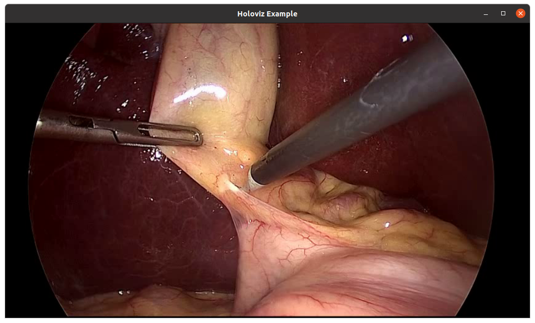
Holoviz provides the functionality to composite real-time streams of frames with multiple different other layers like segmentation mask layers, geometry layers, and GUI layers.
For maximum performance, Holoviz makes use of Vulkan, which is already installed as part of the NVIDIA GPU driver.
Holoscan provides the Holoviz operator which is sufficient for many, even complex visualization tasks. The Holoviz operator is used by multiple Holoscan example applications.
Additionally, for more advanced use cases, the Holoviz module can be used to create application-specific visualization operators. The Holoviz module provides a C++ API and is also used by the Holoviz operator.
The term Holoviz is used for both the Holoviz operator and the Holoviz module below. Both the operator and the module roughly support the same feature set. Where applicable, information on how to use a feature with the operator and the module is provided. It’s explicitly mentioned below when features are not supported by the operator.
Layers
The core entity of Holoviz are layers. A layer is a two-dimensional image object. Multiple layers are composited to create the final output.
These layer types are supported by Holoviz:
- Image layer
- Geometry layer
- GUI layer
All layers have common attributes which define the look and also the way layers are finally composited.
The priority determines the rendering order of the layers. Before rendering, the layers are sorted by priority. The layers with the lowest priority are rendered first, so that the layer with the highest priority is rendered on top of all other layers. If layers have the same priority, then the render order of these layers is undefined.
The example below draws a transparent geometry layer on top of an image layer (geometry data and image data creation is omitted in the code). Although the geometry layer is specified first, it is drawn last because it has a higher priority (1) than the image layer (0).
Operator
Module
The operator has a receivers port which accepts tensors and video buffers produced by other operators. Each tensor or video buffer will result in a layer.
The operator autodetects the layer type for certain input types (e.g., a video buffer will result in an image layer).
For other input types or more complex use cases, input specifications can be provided either at initialization time as a parameter or dynamically at runtime.
Image Layers
Operator
Module
Image data can either be on host or device (GPU); both tensors and video buffers are accepted.
Supported Image Formats
Operator
Module
Supported formats for nvidia::gxf::VideoBuffer.
Image format detection for nvidia::gxf::Tensor. Tensors don’t have image format information attached. The Holoviz operator detects the image format from the tensor configuration.
Geometry Layers
A geometry layer is used to draw 2d or 3d geometric primitives. 2d primitives are points, lines, line strips, rectangles, ovals or text and are defined with 2d coordinates (x, y). 3d primitives are points, lines, line strips or triangles and are defined with 3d coordinates (x, y, z).
Coordinates start with (0, 0) in the top left and end with (1, 1) in the bottom right for 2d primitives.
Operator
Module
See holoviz_geometry.cpp and holoviz_geometry.py for 2d geometric primitives and and holoviz_geometry.py for 3d geometric primitives.
ImGui Layers
ImGui layers are not supported when using the Holoviz operator.
The Holoviz module supports user interface layers created with Dear ImGui.
Calls to the Dear ImGui API are allowed between viz::BeginImGuiLayer and viz::EndImGuiLayer, and are used to draw to the ImGui layer. The ImGui layer behaves like other layers and is rendered with the layer opacity and priority.
The code below creates a Dear ImGui window with a checkbox used to conditionally show a image layer.
ImGUI is a static library and has no stable API. Therefore, the application and Holoviz have to use the same ImGUI version. When the link target holoscan::viz::imgui is exported, make sure to link your application against that target.
Depth Map Layers
A depth map is a single channel 2d array where each element represents a depth value. The data is rendered as a 3D object using points, lines, or triangles. The color for the elements can also be specified.
Supported formats for the depth map:
- 8-bit unsigned normalized format that has a single 8-bit depth component
- 32-bit signed float format that has a single 32-bit depth component
Supported format for the depth color map:
- 32-bit unsigned normalized format that has an 8-bit R component in byte 0, an 8-bit G component in byte 1, an 8-bit B component in byte 2, and an 8-bit A component in byte 3
Depth maps are rendered in 3D and support camera movement.
Operator
Module
Views
By default, a layer will fill the whole window. When using a view, the layer can be placed freely within the window.
Layers can also be placed in 3D space by specifying a 3D transformation matrix.
For geometry layers, there is a default matrix which allows coordinates in the range of [0 … 1] instead of the Vulkan [-1 … 1] range. When specifying a matrix for a geometry layer, this default matrix is overwritten.
When multiple views are specified, the layer is drawn multiple times using the specified layer view.
It’s possible to specify a negative term for height, which flips the image. When using a negative height, you should also adjust the y value to point to the lower left corner of the viewport instead of the upper left corner.
Operator
Module
See holoviz_views.py.
Camera
When rendering 3d geometry using a geometry layer with 3d primitives or using a depth map layer the camera properties can either be set by the application or interactively changed by the user.
To interactively change the camera, use the mouse:
- Orbit (LMB)
- Pan (LMB + CTRL | MMB)
- Dolly (LMB + SHIFT | RMB | Mouse wheel)
- Look Around (LMB + ALT | LMB + CTRL + SHIFT)
- Zoom (Mouse wheel + SHIFT)
Operator
Module
See holoviz_camera.cpp.
Using a Display in Exclusive Mode
Typically, Holoviz opens a normal window on the Linux desktop. In that case, the desktop compositor is combining the Holoviz image with all other elements on the desktop. To avoid this extra compositing step, Holoviz can render to a display directly.
Configure a Display for Exclusive Use
Single display
Multiple displays
SSH into the machine and stop the X server:
To resume the display manager, run:
Enable Exclusive Display in Holoviz
Operator
Module
Arguments to pass to the Holoviz operator:
The name of the display can either be the EDID name as displayed in the NVIDIA Settings, or the output name provided by xrandr or
hwinfo --monitor.
X11
Wayland and X11
In this example output of xrandr, DP-2 would be an adequate display name to use:
CUDA Streams
By default, Holoviz is using CUDA stream 0 for all CUDA operations. Using the default stream can affect concurrency of CUDA operations, see stream synchronization behavior for more information.
Operator
Module
The operator is using a holoscan::CudaStreamPool instance if provided by the cuda_stream_pool argument.
The stream pool is used to create a CUDA stream used by all Holoviz operations.
Reading the Frame Buffer
The rendered frame buffer can be read back. This is useful when doing offscreen rendering or running Holoviz in a headless environment.
Operator
Module
To read back the color or depth frame buffer, set the enable_render_buffer_output or enable_depth_buffer_output_ parameter to true and provide an allocator to the operator.
The color frame buffer is emitted on the render_buffer_output port, the depth frame buffer is emitted on the depth_buffer_output port.
sRGB
The sRGB color space is supported for both images and the framebuffer. By default Holoviz is using a linear encoded framebuffer.
Operator
Module
To switch the framebuffer color format set the framebuffer_srgb parameter to true.
To use sRGB encoded images set the image_format field of the InputSpec structure to a sRGB image format.
HDR
Holoviz supports selecting the framebuffer surface image format and color space. To enable HDR select a HDR color space.
Operator
Module
Set the framebuffer_color_space parameter to a supported HDR color space.
Distributions supporting HDR
At the time of writing (08/2024) there is currently no official support for HDR on Linux. However there is experimental HDR support for Gnome version 44 and KDE Plasma 6.
KDE Plasma 6
Experimental HDR support is described in this blog post. Three steps are required to use HDR with Holoviz:
- Enable HDR in the display configuration
- Install the Vulkan HDR layer
- Set the
ENABLE_HDR_WSIenvironment variable to1.
Run vulkaninfo to verify that HDR color spaces are reported
Gnome version 44
Gnome version 44 is part of Ubuntu 24.04.
Experimental HDR support had been added with this MR. To enable HDR, make sure Wayland is used (no HDR with X11), press Alt+F2, then type lg in the prompt to start the looking glass console. Enter global.compositor.backend.get_monitor_manager().experimental_hdr = 'on' to enable HDR, global.compositor.backend.get_monitor_manager().experimental_hdr = 'off' to disable HDR.
Gnome is not yet passing the HDR color space to Vulkan. The color space and other information can be queried using drm_info, check modes where HDR_OUTPUT_METADATA is not 0.
For the case below (Microstep MSI MPG343CQR display) the HDR color space is BT2020_RGB with SMPTE ST 2084 (PQ) EOTF. Max luminance is 446 nits.
Callbacks
Callbacks can be used to receive updates on key presses, mouse position and buttons, and window size.
Operator
Module
C++
Scheduling Conditions
Holoviz provides specialized scheduling conditions that enable operators to synchronize their execution with display events. These conditions are particularly useful for rate-limiting and ensuring that frame generation is synchronized with the display’s refresh cycle, reducing latency and improving visual quality.
FirstPixelOut Condition
The C++ (holoscan::FirstPixelOutCondition) allows an operator to synchronize its execution with the time when the first pixel of the next display refresh cycle leaves the display engine for the display (FirstPixelOut). By synchronizing with FirstPixelOut, applications can ensure minimal tearing and optimal frame pacing.
The condition internally waits for the next FirstPixelOut signal from the display hardware. When FirstPixelOut occurs, the condition transitions to a ready state, allowing the operator to execute. After execution, the condition transitions back to a waiting state until the next FirstPixelOut.
Use cases:
- Synchronizing frame generation with display refresh rate
- Minimizing display tearing in real-time visualization
- Rate-limiting operators to match the display’s capabilities
Present Done Condition
The C++ (holoscan::PresentDoneCondition) allows an operator to synchronize its execution with the completion of frame presentation. This condition waits until a specific frame has been fully presented to the display before allowing the next operator execution.
The condition tracks presentation IDs, which increment with each frame presented. It blocks until a specific presentation ID is reached or a timeout occurs, ensuring that the application doesn’t generate frames faster than the display can present them.
This condition requires the VK_KHR_present_wait Vulkan device extension. On hardware where it is not available (e.g. Orin iGPU, IGX Thor + Blackwell dGPU configurations), the underlying Vulkan::Impl::wait_for_present throws a std::runtime_error. PresentDoneCondition catches the exception, logs an ERROR identifying the missing extension, and calls Fragment::stop_execution() so the application shuts down gracefully (cleanly, with a non-zero-frame log trail) instead of std::terminate()-ing from its background thread. Use FirstPixelOutCondition as an alternative, or verify extension support with vulkaninfo | grep VK_KHR_present_wait before using this condition.
Applications using this condition might hang or crash when using tools to remotely access the desktop.
Use cases:
- Preventing frame queue buildup by matching generation to presentation rate
- Reducing end-to-end latency in interactive applications
- Ensuring smooth frame pacing without dropped frames
Example Usage
The holoviz_conditions example demonstrates how to use these conditions to rate-limit a source operator:
Multiprocess Synchronization
The HoloViz operator supports multiprocess synchronization using a file-based
FIFO mutex in the /tmp/ directory. This enables better predictability with the
maximum end-to-end latency of the Holoscan SDK applications.
The support for this mutex is enabled by setting the environment variable
HOLOSCAN_HOLOVIZ_MUTEX to 1.
When the environmentvariable is not set, the HoloViz operator will not use the mutex, and there will be no attempt at explicit multiprocess synchronization.
When using the mutex, developers can optionally enable dropping frames for
an upper bound on the latency of the HoloViz operator. Setting HoloViz
operator’s multiprocess_framedrop_waittime_ms parameter to a non-zero value
will drop frames when the mutex is not available for locking, even after waiting
for the specified amount of time in ms. In this case, the number of dropped
frames will be logged at the end of an application. Setting the parameter to 0,
which is the default value, will not drop any frames.
Although we do support automatic cleanup of the Holoviz mutex lock and mutex
queue files, an unexpected application crash or undefined application behavior
may not properly clear those files before shutting down. In that case, manually remove
those files (e.g., rm -f /tmp/holoscan_holoviz_mutex*).
Holoviz operator
Class Documentation
C++ (holoscan::ops::HolovizOp)
Python (holoscan.operators.HolovizOp).
Holoviz Operator Examples
There are multiple examples, both in Python and C++, showing how to use various features of the Holoviz operator.
Holoviz module
Concepts
The Holoviz module uses the concept of the immediate mode design pattern for its API, inspired by the Dear ImGui library. The difference to the retained mode, for which most APIs are designed, is that there are no objects created and stored by the application. This makes it fast and easy to make visualization changes in a Holoscan application.
Instances
The Holoviz module uses a thread-local instance object to store its internal state. The instance object is created when calling the Holoviz module is first called from a thread. All Holoviz module functions called from that thread use this instance.
When calling into the Holoviz module from other threads other than the thread from which the Holoviz module functions were first called, make sure to call viz::GetCurrent() and viz::SetCurrent() in the respective threads.
There are usage cases where multiple instances are needed; for example, to open multiple windows. Instances can be created by calling viz::Create(). Call viz::SetCurrent() to make the instance current before calling the Holoviz module function to be executed for the window the instance belongs to.
Getting Started
The code below creates a window and displays an image.
First, the Holoviz module needs to be initialized. This is done by calling viz::Init().
The elements to display are defined in the render loop; termination of the loop is checked with viz::WindowShouldClose.
The definition of the displayed content starts with viz::Begin, and ends with viz::End. viz::End starts the rendering and displays the rendered result.
Finally, the Holoviz module is shutdown with viz::Shutdown.
Result:
API
Holoviz Module Examples
There are multiple examples showing how to use various features of the Holoviz module.
Fullscreen vs Exclusive Display Mode
Holoviz offers two different modes for rendering to a display taking up the entire screen: fullscreen mode and exclusive display mode. While both modes render content to fill the entire display, they differ significantly in how they interact with the windowing system.
Fullscreen Mode
Fullscreen mode creates a borderless window that covers the entire display using GLFW (Graphics Library Framework). In this mode:
- Window Manager Integration: The window is still managed by the Linux window manager. Keyboard and mouse interactions are supported.
- Desktop Compositor: When the window covers the entire screen, the desktop compositor switches to flip mode, bypassing the compositing step. Therefore, the performance in fullscreen mode is better than in the windowed mode. However, the desktop compositor is still involved in the rendering path.
- Simpler Setup: No special display configuration is required. The application can switch to full-screen mode at runtime.
- G-SYNC Support: G-SYNC is supported in fullscreen mode once it is enabled from NVIDIA Control Panel.
To enable fullscreen mode, set the fullscreen parameter to true:
Operator (C++)
Operator (Python)
Exclusive Display Mode
Exclusive display mode renders directly to a display using Vulkan’s
VK_KHR_display extension, completely bypassing the window manager and desktop
compositor. This mode takes up the entire screen, just like the fullscreen mode.
However, there are a few differences with the fullscreen mode. In this mode:
- Direct Rendering: The GPU writes pixels to a memory area, and the display controller reads from this memory and sends the pixels to the display. Vulkan’s present call switches which memory region the display controller reads from, bypassing the window manager and compositor.
- Performance: Eliminating the involvement of the window manager anddesktop compositor altogether, this mode provides maximum rendering performance and minimal latency.
- Display Control: Takes exclusive control of the specified display, preventing other applications from using it. Keyboard and mouse interactions are not supported.
- Setup Required: Requires the display to be disabled in the X server configuration or the display manager to be stopped (see Configure a Display for Exclusive Use).
- Vulkan Extensions: Uses Vulkan’s direct display extensions.
- G-SYNC Support: G-SYNC is currently not supported in exclusive display mode.
To enable exclusive display mode, set the use_exclusive_display parameter to
true (as shown in Enable Exclusive Display in
Holoviz).