Architecture#
Overview#
The PVA engine is a VLIW SIMD DSP which is optimized for implementing image processing and computer vision algorithms, available on certain NVIDIA SOCs. Key places where PVA’s capabilities are a good match are algorithmic domains where we need to have predictable processing, at low power and low latency. PVA shines on semi-dense or dense regular computation, even on small data sets, which need predictable run-times with low latency and low power.
The PVA SDK provides libraries, headers, and tools for writing, debugging and optimizing applications for the PVA.
A PVA application consists of host code and device code:
Host code is used to configure a PVA program. This code runs on the SOC’s CPU. It is responsible for setting up DMA operations via Dataflow abstractions, allocating resources for applications, and handling scheduling with other engines.
Device code is the code which runs on the PVA’s vector processing unit (VPU). It is responsible for triggering DMA operations and processing data.
Both host and device code use the cuPVA runtime to interact with the PVA engine.
PVA Processor#
PVA processor architecture contains two Vector Processing Subsystems (VPS) and a Control Subsystem (Cortex-R5). Each VPS may be independently programmed by the user. The Control Subsystem schedules work between the two VPSs and is not available for user programming.
A simplified block diagram is depicted in Figure 1.
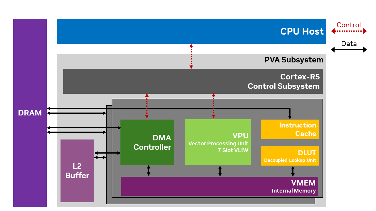
Figure 1: PVA Architecture#
Each component of the PVA is described in detail below.
VPU#
The Vector Processing Unit (VPU) is the main processing engine of the PVA. VPU is closely tied together with VMEM, DLUT and Instruction cache to form the VPS (Vector Processing Subsystem).
The VPU instruction format is 7-way VLIW, consisting of:
2 scalar ALUs
2 vector ALUs
3 load/store units
Vector ALUs are the heavy lifters for image processing and computer vision kernels. The Wide SIMD vector unit executes up to 2 vector math instructions per cycle. Each VPU SIMD instruction can process 32 pixels (12-bits per pixel), in parallel. An extensive set of general and CV specific Integer arithmetic/logic operations and Floating Point arithmetic and math operations are supported.
VMEM#
VPU vector memory (VMEM) houses local data memory for VPU so that various image processing and computer vision algorithms can be implemented efficiently. VMEM supports various complex memory access patterns, including consecutive read/write of various lengths, transposition, table lookup, histogram and vector addressed stores.
DLUT#
Each VPS includes a decoupled look-up table unit (DLUT). The DLUT can operate concurrently and in parallel with the VPU to offload VMEM lookup operations. DLUT offers high throughput lookup operations with hardware acceleration to minimize memory bank conflicts. The DLUT may be used from VPU via the Sampler API.
DMA Controller#
VPU can only load from or store to its internal memory, VMEM. VPU needs the Direct Memory Access (DMA) engine to move data among external memory, L2 memory and VMEM. Each VPS block within PVA has a dedicated DMA engine and each DMA engine has multiple channels that can move data from multiple source locations to destination locations in parallel. Memory read/write operations can be done in parallel with the VPU processes to hide the data access latency. Each VPU and DMA pair synchronize between themselves on tile granularity. Tiles are typically sub-blocks of the application’s input/output dataset from external memory and there are typically tens to hundreds of tiles per task. The tiles are sized to fit within VMEM, and the DMA engine is used to traffic these sub-blocks to VMEM for VPU processing.
L2 Buffer#
PVA employs an L2 memory that is shared between the two sets of VPS and DMA. L2 buffer size is larger than VMEM and has a higher bandwidth than the external DRAM. It can be used to fetch data blocks that cannot fit to VMEM or as a scratch buffer.
Debug hardware#
Each VPU has a CoreSight/APB-based debug interface connected to a system-level JTAG interface. It is accessible through JTAG or through CPU software. The VPU supports typical symbolic debug features such as:
Read/write VMEM
Read/write processor registers
Single stepping
24 hardware watch/break points
Unlimited software breakpoints
To use the VPU debug hardware, refer to On-Chip debugging.
Control Subsystem (Cortex-R5)#
PVA has a control subsystem, Cortex-R5. Cortex-R5 is the main orchestrator of tasks running on PVA as well as its external interface. It interacts with host CPU, GPU, other CV system engines including ISP and hardware accelerators such as NVENC.
R5 configures, controls and monitors VPU and DMA tasks that are needed for PVA functions. R5 configures DMA, optionally prefetches VPU program into VPU Instruction cache, and kicks off each VPU-DMA pair to process a task that runs for typically hundreds of micro-seconds to a few milli-seconds.
For a cuPVA program, the R5 acts as an opaque scheduler and is not exposed as part of the cuPVA programming model.
Safety Usage#
Hardware#
In accordance with ISO 26262-5; 7.1.2, the ASIL supported by PVA hardware is ASIL-D systematic and ASIL-B random.
Software#
The safety builds of the cuPVA host and device runtimes are candidates for safety certification at ASIL-B level when used as part of a suitable DRIVE OS safety release. Refer to the certification to determine which versions of the cuPVA runtime are suitable for safety use and the appropriate DRIVE OS version.
The majority of the cuPVA host and device APIs are provided in safety builds, meaning applications developed on non-safety DRIVE OS versions can be easily ported to safety builds in most cases. There are a few exceptions to this rule, relating to debugging APIs and features not available in safety builds.
APIs which are not available in safety builds may be identified in the following ways:
All such APIs are defined in headers which are prefaced by a guard which requires the preprocessor token
PVA_ALLOW_NONSAFETYto be set to 1. If this is not set, and the file is included, the preprocessor generates an error. PVA SDK build scripts set this token to 1 ifPVA_SAFETYis not set as a CMake option.All such APIs are clearly marked in the documentation.
Host API#
Overview#
The Host API is designed to assist the user in doing all necessary setup steps on the SOC’s CPU, before handing execution over to the PVA. The following describes typical host code steps to configure of a simple application, synchronous with the CPU:
Allocate buffers using Memory APIs
Create
cupva::Executableandcupva::CmdProgram(see Task Configuration)Configure the Dataflows of the CmdProgram
Compile data flows with
cupva::CmdProgram::compileDataFlows()Configure synchronization commands, for example to request a
cupva::Fenceusing Task Scheduling API.Submit the
cupva::CmdProgramand any synchronization commands to acupva::StreamWait on
cupva::Fence
For more detailed examples of usage, please see the samples distributed with the SDK or the Tutorials.
Context Management#
Many cuPVA APIs require a Context to be current on the calling thread. The Context that is current to a
thread can be set by calling cupva::Context::SetCurrent() from the thread. Creating a Context also causes the new Context to become current on the calling thread.
If an API requiring a Context is called from a thread that does not have a current Context, a default process-wide Context is used. This Context is only created when it is needed, and is destroyed when the process exits.
There is a system-wide limit on the number of Contexts that may be created across all processes, including default Contexts. On currently supported platforms, this limit is 4. Exceeding this limit causes future Context creation to fail.
Error Reporting#
The cuPVA host API is a C++17 API that reports failure via throwing exceptions. The possible exception types are cupva::Exception
as well as C++ standard library exceptions. All APIs provide an exception specification for the possible exceptions that they may throw. Users must catch all possible exceptions where process termination is not the desired behavior.
Host API Thread-Safety#
Each Host API is marked as being thread-safe or not thread-safe. An API is marked as thread-safe if and only if it is guaranteed to conform to its interface specification and avoid unintended behavior when called from multiple threads simultaneously with some reference or pointer arguments being shared. Likewise, different APIs marked as thread-safe may also be called from multiple threads simultaneously with shared reference or pointer arguments.
For the purposes of this definition, the implied ‘this’ pointer for non-static class member functions does count as an argument, but any other implied arguments (for example, the current cuPVA context) do not count as arguments.
All cuPVA host APIs are guaranteed to conform to their interface specification when all reference/pointer arguments are
different between simultaneous calls from different threads. Any global state is synchronized between threads internally in
such cases. For example, calling cupva::StaticDataFlow::src() on two different objects from two different threads is safe.
Calling this method on the same cupva::StaticDataFlow object from two different threads is not safe. Likewise, move and copy
assignment may be invoked on unrelated objects simultaneously from different threads.
The user must ensure that multiple threads do not simultaneously use APIs in violation of their concurrency specifications. Failure to follow the specification can lead to data corruption and race conditions.
Host API Design Concepts#
The Host API is designed around three distinct phases of an application: init, steady state and deinit.
APIs which can be used at init time may allocate heap and are not intended to be used in performance critical loops.
Steady state APIs and objects do not allocate heap and are optimized for use in a frame loop.
Deinit APIs are intended to be used for application tear-down only.
To help the user understand which objects allocate heap and are therefore intended to be created only at init time, such objects must be created via a static Create() method, for example Executable::Create(). Objects without such a method
may be created and initialized normally via available constructors.
Note
Many objects with Create methods also have default constructors. This is to allow use in STL containers. Such objects still need to be initialized by assigning them the result of a call to Create() before they can be used.
In addition, some methods are designated as init-time only APIs, since they cause heap allocation.
Note
In general, an application using PVA transitions to steady-state after it has called cupva::CmdProgram::compileDataflows() for
each CmdProgram it intends to use. After this point, the only changes that can be made to the DMA configuration
of a program without recompiling are Dataflows data pointers by using
OffsetPointer API.
Dataflows#
The PVA’s DMA engine is a powerful multi-dimensional engine for moving data from generally accessible memories to memories which can be used by the PVA and VPU, and vice-versa. Each cuPVA program is allocated a DMA engine for its use during run-time. A cuPVA CmdProgram needs to request DMA setup for its needed data transfers.
Note
The PVA’s VPU engines cannot access data memory other than VMEM without use of the DMA.
The core software abstraction used to represent data transfers in cuPVA is the Dataflow. Dataflows come in 4 varieties:
StaticDataFlowis a thin wrapper over a raw DMA descriptor. Many DMA descriptor fields are freely programmable via the methods onStaticDataFlow
ConfigDataFlow(deprecated) is an abstraction for the concept of re-configuring another DMA descriptor. SeeDynamicDataFlow.
RasterDataFlowis an abstraction over a number of DMA descriptors and DMA resources, as required for performing a raster scan over an image. On some PVA hardware, certain raster scan patterns require multiple DMA channels and descriptors. The number of channels/descriptors required can change based on the exact image/tile dimensions and the use of padding.
DynamicDataFlowis an abstraction for tile fetching using parameters available only at run-time. Two modes are available: 2D and 1D. In 2D mode, there are N channels each fetching M tiles in a single trigger/sync cycle. In 1D mode, there is only a single channel, though the number of tiles fetched is still configurable.
The DataFlow host APIs define a contract which must be met by the users’ device code. For example, if a DataFlow is set
up to require a certain number of triggers, then the VPU code must ensure exactly that number of triggers are
provided at run-time. This requirement must be satisfied on every possible branch. The configurable nature of
DynamicDataFlow does not require a fixed number of triggers. There are VPU APIs to open and close a
DynamicDataFlow, and a variable number of triggers may occur in between. It is also possible to link multiple StaticDataFlow in
a circular chain which would repeat endlessly and must be broken by ConfigDataFlow (deprecated), however DynamicDataFlow
is the preferred method to handle this use case.
Note
Failure to trigger a configured DMA channel to completion can lead to timeouts and have unpredictable effects on run-time for the entire PVA engine.
Dataflow objects are created to be associated with CmdProgram objects. Two APIs exist for this: CmdProgram::addDataFlow and CmdProgram::addDataFlowHead. The difference between these is that CmdProgram::addDataFlowHead allocates a DMA channel and start the DMA channel with this DataFlow. On the other hand, CmdProgram::addDataFlow does not initialize a DMA channel. Such a DataFlow is only executed when it is linked to from a “head.”
NvSci Interop#
The cuPVA Host API contains global functions designed to create cuPVA objects from NvSci objects and vice-versa. Since these APIs introduce an application level dependency on NvSci libraries and headers, they are defined in a separate header, cupva_host_nvsci.hpp. It is expected that users provide the necessary libraries or headers from NvSci to resolve these dependencies at build time.
Since the NvSci APIs interoperate with standard cuPVA objects, support for interop via NvSci can be added onto an existing application via a thin translation layer, with no impact on the underlying application implementation. Therefore, the same application or collection of applications can be used with or without NvSci.
Block Linear Surfaces#
A device pointer can be associated with surface metadata, for example when the device pointer represents a surface imported from NvSci. A surface may have block linear or pitch linear layout. Regardless of the surface layout, cuPVA host APIs always assume a pitch linear layout, with pitch specified by the cuPVA GetSurfaceAttributes API. For example:
// This function always returns a device pointer pointing to a pixel in the surface
// offset by 2 rows, regardless of whether the surface is block linear or pitch linear
const int8_t *offsetTwoRows(const int8_t *src_d)
{
  cupva::mem::SurfaceAttributes attr;
  cupva::mem::GetSurfaceAttributes(src_d, attr);
  uint32_t linePitch = attr.planes[planeIdx].linePitch;
  return src_d + 2 * linePitch;
}
Similarly, the “advance” fields of DataFlows should be configured for pitch linear layout, regardless of the actual layout of the surface.
When using VPU config with surfaces, src and dst fields of the DMA descriptor must be programmed
with real addresses, rather than pitch linear equivalents. Advancement fields should continue to
use pitch linear addressing. To determine the correct block-linear address for src/dst fields,
extra surface metadata is required. This may be written to VMEM by using the VMEM_SURFACE macro as
a replacement for VMEM_POINTER. The user can then use cupvaSurfaceAddress2D() device side APIs to
calculate the correct address to use with VPU config.
There are additional alignment constraints when using block linear surfaces with DataFlow APIs. Pointers to block linear surfaces must be aligned to 32 bytes horizontally and 2 rows vertically. Advancement fields (for example, in dim1/dim2/dim3 APIs) must also result in 32Bx2 alignment.
Device API#
Overview#
The cuPVA Device API is used to query core run-time information during VPU execution, and synchronize DataFlows which were configured from Host code. It also provides some helpers to assist users in writing VPU code; for example, configuring AGENs used by the VPU.
Device APIs are generally delivered as source in headers, with only a thin binary runtime. This allows the majority of functions used within an application to be inlined. This is useful in VPU code, where branching to non-local code locations can be costly in some cases.
For full details on available APIs in VPU code, refer to Device API.