Raster Data Flow (RDF) and Tiles#
In this tutorial we implement a simple image enhancement algorithm called contrast stretching. This algorithm transforms pixel intensity values to span the whole available dynamic range using a piecewise linear mapping function.
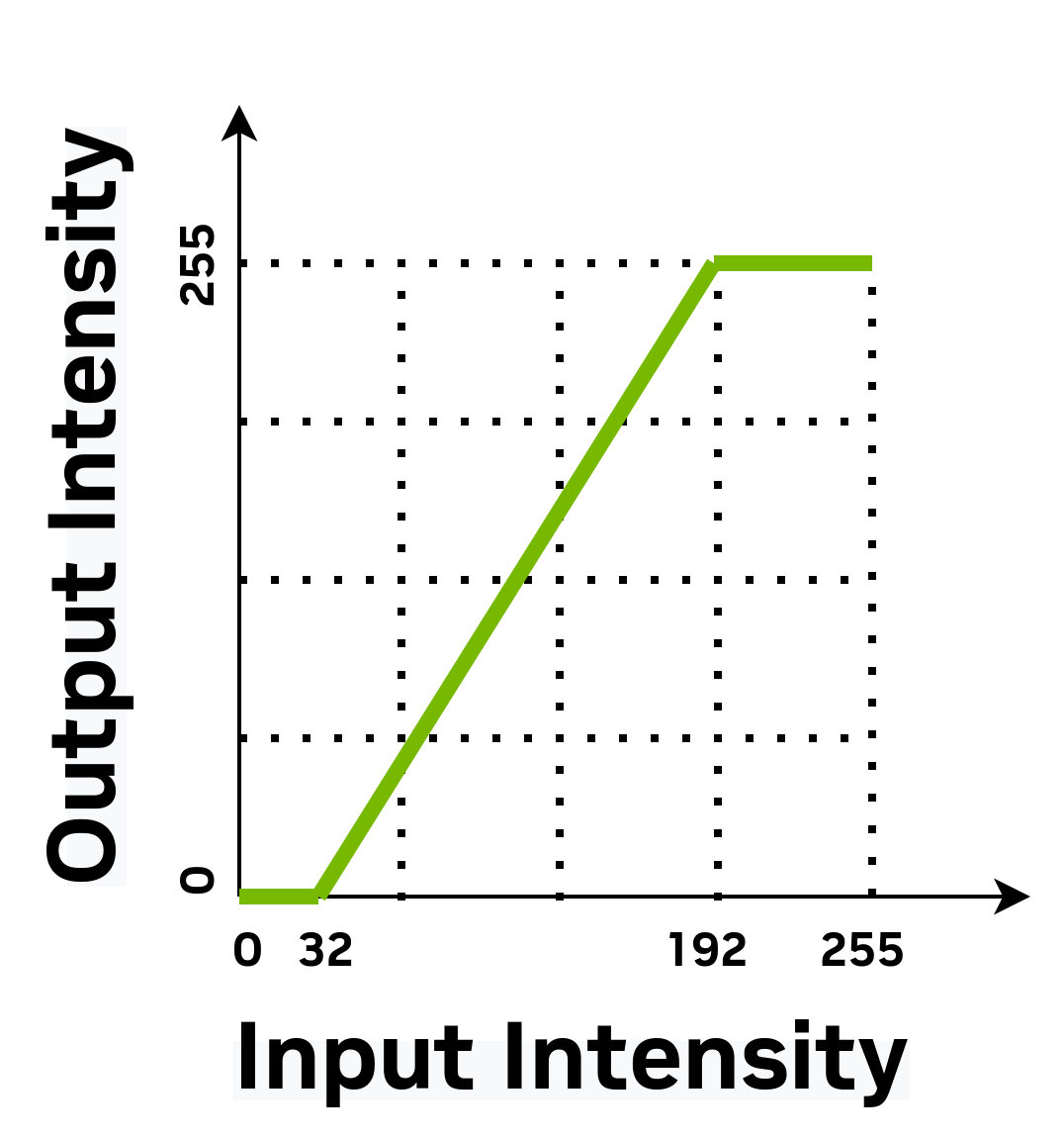
Contrast Stretching - Intensity Transformation#
The application reads the input from a grayscale raw image file and writes back the enhanced image file.
As we have mentioned earlier, the VPU engines can only access data from their internal VMEM. In most use cases, a whole image does not fit into VMEM at once. To overcome this issue, cuPVA provides support to transfer data to and from VMEM in chunks called tiles using PVA’s DMA engine. Tiles can be defined in 2D, which is ideal for image processing operations. cuPVA makes it easy to process a whole image tile by tile using the Raster DataFlow API.
In this tutorial, we introduce:
How to configure Raster DataFlows (RDF).
How to trigger tile data transfers from the device code to loop over an image.
How to allocate VMEM buffer to hold the tile data.
Device Code#
Tile width and height should be set consistently on both host and device code. Consistency lets device code to allocate enough VMEM buffer that can hold the transferred tile data. It is a good practice to declare these parameters in a common header file that is included from both the device and host codes.
#include "../raster_data_flow_common_params.h"
In this tutorial we set both TILE_WIDTH and TILE_HEIGHT to 64 pixels. Tile size should be selected based on the details of the application to balance performance, which are covered in later tutorials.
Contrast stretching algorithm parameters structure is also defined in the common header file. The structure is initialized in the host side and used in the device code.
#define TILE_WIDTH 64
#define TILE_HEIGHT 64

typedef struct
{
    uint8_t inputLowPixelValue;
    uint8_t outputLowPixelValue;
    uint8_t inputHighPixelValue;
    uint8_t outputHighPixelValue;
} ContrastStretchParams;
Let’s declare buffers that hold the input and output tiles of the image data. The RDF_SINGLE helper macro can be used to get the VMEM size needed to store one tile. Type, width, and height of the 2-D image tile are passed as arguments. There are also some optional macro arguments, which are introduced in the upcoming tutorials. RDF requires certain size alignment and the helper macros ensure that requirements are satisfied.
The number of tiles in the image is set by the host code. We use the tileCount variable to set the number of outer loop iterations.
#include <cupva_device.h> /* Main device-side header file */

VMEM(A, uint8_t, inputTileBufferVMEM, RDF_SINGLE(uint8_t, TILE_WIDTH, TILE_HEIGHT));
VMEM(B, uint8_t, outputTileBufferVMEM, RDF_SINGLE(uint8_t, TILE_WIDTH, TILE_HEIGHT));

VMEM(C, int32_t, tileCount);
The handles that are used for triggering and syncing tile transfers are declared for both incoming source and outgoing destination data flows. Host-side code uses these handles when configuring the RDFs.
VMEM_RDF_UNIFIED(A, sourceDataFlowHandler);
VMEM_RDF_UNIFIED(A, destinationDataFlowHandler);
We allocate VMEM space to hold the contrast stretching algorithm parameters structure. Host-side code uses the same structure to set the input/output linear mapping of intensity values.
VMEM(C, uint8_t, algorithmParams, sizeof(ContrastStretchParams));
The input dynamic range that are stretched and dynamic range after enhancement is pre-computed before the processing loop.
CUPVA_VPU_MAIN()
{
    ContrastStretchParams *params = (ContrastStretchParams *)algorithmParams;
    uint8_t inputDynamicRange     = params->inputHighPixelValue - params->inputLowPixelValue;
    uint8_t outputDynamicRange    = params->outputHighPixelValue - params->outputLowPixelValue;
    int32_t outputPixelValue;
The line pitch in pixels for the input and output RDF tile buffers are read using cuPVA APIs. These values are used in addressing the pixels while loading from and storing to the tile buffers.
    int32_t srcLinePitch = cupvaRasterDataFlowGetLinePitch(sourceDataFlowHandler);
    int32_t dstLinePitch = cupvaRasterDataFlowGetLinePitch(destinationDataFlowHandler);
The outer loop of the device side code iterates over the tiles. In this example we first call cupvaRasterDataFlowOpen outside of the loop, which puts the RasterDataFlows in a state where tile memory in VMEM can be acquired. The pointer passed as the second argument to this function should match the vmemBuffer configured in host code.
Inside the loop, we acquire tiles within each of the source and destination buffers. The acquire call returns a pointer to the base of the tile. After acquiring a tile, it may be read from/written to until a corresponding call to cupvaRasterDataFlowRelease.
It is critical that a cupvaRasterDataFlowAcquire/Release pair is called for every tile of the image (per host side configuration), or else the DMA hardware will hang.
    cupvaRasterDataFlowOpen(sourceDataFlowHandler, &inputTileBufferVMEM[0]);
    cupvaRasterDataFlowOpen(destinationDataFlowHandler, &outputTileBufferVMEM[0]);

    for (int32_t i = 0; i < tileCount; i++)
    {
        int8_t *inputTile  = (int8_t *)cupvaRasterDataFlowAcquire(sourceDataFlowHandler);
        int8_t *outputTile = (int8_t *)cupvaRasterDataFlowAcquire(destinationDataFlowHandler);
The inner pixel processing loop maps input pixel intensities to the output dynamic range. The min-max clipping is needed to keep output pixel value within the 0 to 255 range.
        for (int32_t i = 0; i < TILE_HEIGHT; i++)
        {
            for (int32_t j = 0; j < TILE_WIDTH; j++)
            {
                outputPixelValue = outputDynamicRange * (inputTile[i * srcLinePitch + j] - params->inputLowPixelValue);
                outputPixelValue /= inputDynamicRange;
                outputPixelValue += params->outputLowPixelValue;
                outputPixelValue =
                    max(params->outputLowPixelValue, min(outputPixelValue, params->outputHighPixelValue));
                outputTile[i * dstLinePitch + j] = (uint8_t)outputPixelValue;
            }
        }
When tiles are released in VMEM, the DMA engine transfers the output tile to the output image in DRAM, and start fetching the next input tile. The next call to
cupvaRasterDataFlowAcquirewaits until these transfers are completed.cupvaRasterDataFlowRelease(sourceDataFlowHandler); cupvaRasterDataFlowRelease(destinationDataFlowHandler); } cupvaRasterDataFlowClose(sourceDataFlowHandler); cupvaRasterDataFlowClose(destinationDataFlowHandler); return 0; }
Host Code#
The application and algorithm parameters are initialized first. The raw grayscale image that this application uses as an input is located in the tutorial assets directory. The enhanced output image is also be written back to the same directory. We use a utility library, which is provided as a party of the tutorials, to read and write raw images. ReadImageBuffer and WriteImageBuffer functions are declared in “ImageIO.h” header file.
Image width and height are defined as constants. The tile dimensions are defined in the common parameters header file that is also included from the device code.
Contrast stretching algorithm parameter structure is also initialized at the beginning of the code. Using these parameters, the algorithm linearly maps pixel intensities in the 32 to 191 range to the 0 to 255 interval.
#include "ImageIO.h"
#include "raster_data_flow_common_params.h"

#include <cupva_host.hpp> // Main host-side C++-API header file

#include <cupva_platform.h> // Header that includes macros for specifying PVA executables

#include <iostream>

using namespace cupva;

PVA_DECLARE_EXECUTABLE(raster_data_flow_dev)

namespace {
std::string inputImageName{"low_contrast_kodim08_768x512_grayscale.data"};
std::string outputImageName{"contrast_stretched_kodim08_768x512_grayscale.data"};

constexpr int32_t IMAGE_WIDTH{768};
constexpr int32_t IMAGE_HEIGHT{512};

constexpr int32_t MAX_IMAGE_PATH_LENGTH{320};
char assetsDirectory[MAX_IMAGE_PATH_LENGTH];

ContrastStretchParams algParams = {.inputLowPixelValue   = 32,
                                   .outputLowPixelValue  = 0,
                                   .inputHighPixelValue  = 191,
                                   .outputHighPixelValue = 255};
} // namespace
The application requires the assets directory path to be passed as an argument. The Executable and CmdProgram instances are created similar to the previous tutorials.
int main(int argc, char **argv)
{
    if (GetAssetsDirectory(argc, argv, assetsDirectory, MAX_IMAGE_PATH_LENGTH) != 0)
    {
        return 0;
    }

    try
    {
        Executable exec = Executable::Create(PVA_EXECUTABLE_DATA(raster_data_flow_dev),
                                             PVA_EXECUTABLE_SIZE(raster_data_flow_dev));
        CmdProgram prog = CmdProgram::Create(exec);
The
Parameter::set()API is used to initialize symbols in VMEM that are declared as arrays, or non-standard types.prog["algorithmParams"].set((uint8_t *)&algParams, sizeof(ContrastStretchParams));
The device-side needs to know how many tile transfers it should trigger. Although the image dimensions in this example are integer multiples of tile dimensions, we show the horizontal and vertical tile count computations for the more general use case. The product of tileCountX and tileCountY gives the total tile count of the image.
        const int32_t tileCountX = (IMAGE_WIDTH + TILE_WIDTH - 1) / TILE_WIDTH;
        const int32_t tileCountY = (IMAGE_HEIGHT + TILE_HEIGHT - 1) / TILE_HEIGHT;
        const int32_t tileCount  = tileCountX * tileCountY;
        prog["tileCount"]        = tileCount;
Buffers for input and output images are allocated in the DRAM using the
mem::Alloc()API. We use theReadImageBuffer()utility function to load the raw image data to the input buffer.uint8_t *inputImage_d = (uint8_t *)mem::Alloc(IMAGE_WIDTH * IMAGE_HEIGHT * sizeof(uint8_t)); uint8_t *inputImage_h = (uint8_t *)mem::GetHostPointer(inputImage_d); if (ReadImageBuffer(inputImageName.c_str(), assetsDirectory, inputImage_h, IMAGE_WIDTH * IMAGE_HEIGHT) != 0) { mem::Free(inputImage_d); return -1; } uint8_t *outputImage_d = (uint8_t *)mem::Alloc(IMAGE_WIDTH * IMAGE_HEIGHT * sizeof(uint8_t)); uint8_t *outputImage_h = (uint8_t *)mem::GetHostPointer(outputImage_d);
Now it is time to configure the Raster DataFlows to move tiles into and out of VMEM.
CmdProgram::addDataFlowHead<RasterDataFlow>()function is used to add a new Raster DataFlow to the CmdProgram. sourceDataFlow transfers input pixels from the DRAM to the VMEM. The DataFlow handle declared in the device code is retrieved and fed as an argument when setting the handler. Note that all DataFlow configuration functions return a reference to the DataFlow instance so that calls can be conveniently chained.RasterDataFlow::src()call sets the source pointer for the transfer and width, height and line pitch attributes of the buffer. The destination VMEM tile buffer pointer is passed as an argument to theRasterDataFlow::tileBuffer()call.RasterDataFlow::tile()API is used to set the width and height of the tile in pixels.RasterDataFlow &sourceDataFlow = prog.addDataFlowHead<RasterDataFlow>(); auto sourceDataFlowHandler = prog["sourceDataFlowHandler"]; uint8_t *inputTileBufferVMEM = prog["inputTileBufferVMEM"].ptr<uint8_t>(); sourceDataFlow.handler(sourceDataFlowHandler) .src(inputImage_d, IMAGE_WIDTH, IMAGE_HEIGHT, IMAGE_WIDTH) .tileBuffer(inputTileBufferVMEM) .tile(TILE_WIDTH, TILE_HEIGHT);
The destinationDataFlow is configured in a similar fashion except that the
dst()API is used to set the output DRAM buffer. This means that the tileBuffer in VMEM is the source for the transfer, and DRAM is the destination. Finally, we compile the DataFlows, which is a required step as mentioned in the previous tutorials.RasterDataFlow &destinationDataFlow = prog.addDataFlowHead<RasterDataFlow>(); auto destinationDataFlowHandler = prog["destinationDataFlowHandler"]; uint8_t *outputTileBufferVMEM = prog["outputTileBufferVMEM"].ptr<uint8_t>(); destinationDataFlow.handler(destinationDataFlowHandler) .tileBuffer(outputTileBufferVMEM) .tile(TILE_WIDTH, TILE_HEIGHT) .dst(outputImage_d, IMAGE_WIDTH, IMAGE_HEIGHT, IMAGE_WIDTH); prog.compileDataFlows();
The rest of the host code is similar to the previous examples. This time we write the enhanced image output to a raw image file after the fence expires.
        SyncObj sync = SyncObj::Create();
        Fence fence{sync};
        CmdRequestFences rf{fence};
        Stream stream = Stream::Create();

        CmdStatus status[2];
        stream.submit({&prog, &rf}, status);

        fence.wait();
        cupva::Error statusCode = CheckCommandStatus(status[0]);
        if (statusCode != Error::None)
        {
            std::cout << "VPU Program returned an Error Code: " << (int32_t)statusCode << std::endl;
        }
        else
        {
            if (WriteImageBuffer(outputImageName.c_str(), ".", outputImage_h, IMAGE_WIDTH * IMAGE_HEIGHT) != 0)
            {
                mem::Free(inputImage_d);
                mem::Free(outputImage_d);
                return -1;
            }
        }
        mem::Free(inputImage_d);
        mem::Free(outputImage_d);
    }
    catch (cupva::Exception const &e)
    {
        std::cout << "Caught a cuPVA exception with message: " << e.what() << std::endl;
        return 1;
    }
    return 0;
}
The application and algorithm parameters are initialized first. The raw grayscale image that this application uses as an input is located in the tutorial assets directory. The enhanced output image is also be written back to the same directory. We use a utility library, which is provided as a party of the tutorials, to read and write raw images.
ReadImageBuffer()andWriteImageBuffer()functions are declared in “ImageIO.h” header file.Image width and height are defined as constants. The tile dimensions are defined in the common parameters header file that is also included from the device code.
Contrast stretching algorithm parameter structure is also initialized at the beginning of the code. Using these parameters, the algorithm linearly maps pixel intensities in the 32 to 191 range to the 0 to 255 interval.
#include "ImageIO.h"
#include "raster_data_flow_common_params.h"

#include <cupva_host.h>
#include <cupva_platform.h>
#include <stdio.h>

#define CHECK_ERROR_GOTO(__v, __e, __l)                  \
    __e = __v;                                           \
    if (__e != CUPVA_ERROR_NONE)                         \
    {                                                    \
        printf("cuPVA C-API return error: %d\n", (__v)); \
        goto __l;                                        \
    }

PVA_DECLARE_EXECUTABLE(raster_data_flow_dev)

#define INPUT_IMAGE_NAME "low_contrast_kodim08_768x512_grayscale.data"
#define OUTPUT_IMAGE_NAME "contrast_stretched_kodim08_768x512_grayscale.data"

#define IMAGE_WIDTH 768
#define IMAGE_HEIGHT 512

#define MAX_IMAGE_PATH_LENGTH 320
char assetsDirectory[MAX_IMAGE_PATH_LENGTH];

ContrastStretchParams algParams = {.inputLowPixelValue   = 32,
                                   .outputLowPixelValue  = 0,
                                   .inputHighPixelValue  = 191,
                                   .outputHighPixelValue = 255};
The application requires the assets directory path to be passed as an argument. The Executable and CmdProgram instances are created similar to the previous tutorials.
int main(int argc, char **argv)
{
    int32_t err = 0;

    if (GetAssetsDirectory(argc, argv, assetsDirectory, MAX_IMAGE_PATH_LENGTH) != 0)
    {
        return 0;
    }

    cupvaExecutable_t exec;
    CHECK_ERROR_GOTO(CupvaExecutableCreate(&exec, PVA_EXECUTABLE_DATA(raster_data_flow_dev),
                                           PVA_EXECUTABLE_SIZE(raster_data_flow_dev)),
                     err, ExecutableCreateFailed);
    cupvaCmd_t prog;
    CHECK_ERROR_GOTO(CupvaCmdProgramCreate(&prog, exec), err, CmdProgramCreateFailed);
The
CupvaParameterSetValueArray()API is used to initialize symbols in VMEM that are declared as arrays, or non-standard types.cupvaParameter_t param; CHECK_ERROR_GOTO(CupvaCmdProgramGetParameter(&prog, ¶m, "algorithmParams"), err, CmdProgramCreateFailed); CHECK_ERROR_GOTO(CupvaParameterSetValueArray(¶m, (uint8_t *)&algParams, sizeof(ContrastStretchParams)), err, CmdProgramCreateFailed);
The device-side needs to know how many tile transfers it should trigger. Although the image dimensions in this example are integer multiples of tile dimensions, we show the horizontal and vertical tile count computations for the more general use case. The product of tileCountX and tileCountY gives the total tile count of the image.
const int32_t tileCount = (IMAGE_WIDTH * IMAGE_HEIGHT) / (TILE_WIDTH * TILE_HEIGHT); CHECK_ERROR_GOTO(CupvaCmdProgramGetParameter(&prog, ¶m, "tileCount"), err, CmdProgramCreateFailed); CHECK_ERROR_GOTO(CupvaParameterSetValueScalar(¶m, &tileCount, sizeof(int32_t)), err, CmdProgramCreateFailed);
Buffers for input and output images are allocated in the DRAM using the
CupvaMemAlloc()API. We use theReadImageBuffer()utility function to load the raw image data to the input buffer.uint8_t *inputImage_d = NULL; CHECK_ERROR_GOTO(CupvaMemAlloc((void **)&inputImage_d, IMAGE_WIDTH * IMAGE_HEIGHT * sizeof(uint8_t), CUPVA_READ_WRITE, CUPVA_ALLOC_DRAM), err, MemAllocFailed); uint8_t *inputImage_h = NULL; CHECK_ERROR_GOTO(CupvaMemGetHostPointer((void **)&inputImage_h, (void *)inputImage_d), err, MemAllocFailed); if (ReadImageBuffer(INPUT_IMAGE_NAME, assetsDirectory, inputImage_h, IMAGE_WIDTH * IMAGE_HEIGHT) != 0) { err = -1; goto MemAllocFailed; } uint8_t *outputImage_d = NULL; CHECK_ERROR_GOTO(CupvaMemAlloc((void **)&outputImage_d, IMAGE_WIDTH * IMAGE_HEIGHT * sizeof(uint8_t), CUPVA_READ_WRITE, CUPVA_ALLOC_DRAM), err, MemAllocFailed); uint8_t *outputImage_h = NULL; CHECK_ERROR_GOTO(CupvaMemGetHostPointer((void **)&outputImage_h, (void *)outputImage_d), err, MemAllocFailed);
Now it is time to configure the Raster DataFlows to move tiles into and out of VMEM.
CupvaCmdProgramAddDataFlowHead()function is used to add a new Raster DataFlow to the CmdProgram. sourceDataFlow transfers input pixels from the DRAM to the VMEM. The DataFlow handle declared in the device code is retrieved and and set as the handler property of the DataFlow parameter struct. Pointer, width, height and line pitch properties are set for the source buffer. Tile buffer pointer declared in the device code is retrieved and used for initializing the destination ptrTileBuffer property. Width and height of the tile in pixels and bytes-per-pixel value should also be set.cupvaDataFlow_t sourceDataFlow; CHECK_ERROR_GOTO(CupvaCmdProgramAddDataFlowHead(&prog, &sourceDataFlow, CUPVA_RASTER_DATAFLOW, 0, 1.0F), err, SyncObjCreateFailed); cupvaParameter_t sourceDataFlowHandler; CHECK_ERROR_GOTO(CupvaCmdProgramGetParameter(&prog, &sourceDataFlowHandler, "sourceDataFlowHandler"), err, SyncObjCreateFailed); uint8_t *inputTileBufferVMEM; CHECK_ERROR_GOTO(CupvaCmdProgramGetParameter(&prog, ¶m, "inputTileBufferVMEM"), err, SyncObjCreateFailed); CHECK_ERROR_GOTO(CupvaParameterGetDevicePointer(¶m, (void const **)&inputTileBufferVMEM), err, SyncObjCreateFailed); cupvaRasterDataFlowParams_t sourceDataFlowParams = {.handler = &sourceDataFlowHandler, .ptrSrc = inputImage_d, .linePitchSrc = IMAGE_WIDTH, .srcWidth = IMAGE_WIDTH, .srcHeight = IMAGE_HEIGHT, .ptrTileBuffer = inputTileBufferVMEM, .tileWidth = TILE_WIDTH, .tileHeight = TILE_HEIGHT, .bpp = sizeof(uint8_t)}; CHECK_ERROR_GOTO(CupvaRasterDataFlowSetParams(sourceDataFlow, &sourceDataFlowParams), err, SyncObjCreateFailed);
The destinationDataFlow is configured in a similar fashion except that the ptrDst property is set to the output DRAM buffer. This means that the tileBuffer in VMEM is the source for the transfer, and DRAM is the destination. Finally, we compile the DataFlows, which is a required step as mentioned in the previous tutorials.
cupvaDataFlow_t destinationDataFlow; CHECK_ERROR_GOTO(CupvaCmdProgramAddDataFlowHead(&prog, &destinationDataFlow, CUPVA_RASTER_DATAFLOW, 0, 1.0F), err, SyncObjCreateFailed); cupvaParameter_t destinationDataFlowHandler; CHECK_ERROR_GOTO(CupvaCmdProgramGetParameter(&prog, &destinationDataFlowHandler, "destinationDataFlowHandler"), err, SyncObjCreateFailed); CHECK_ERROR_GOTO(CupvaCmdProgramGetParameter(&prog, ¶m, "outputTileBufferVMEM"), err, SyncObjCreateFailed); uint8_t *outputTileBufferVMEM; CHECK_ERROR_GOTO(CupvaParameterGetDevicePointer(¶m, (void const **)&outputTileBufferVMEM), err, SyncObjCreateFailed); cupvaRasterDataFlowParams_t destinationDataFlowParams = {.handler = &destinationDataFlowHandler, .ptrDst = outputImage_d, .linePitchDst = IMAGE_WIDTH, .dstWidth = IMAGE_WIDTH, .dstHeight = IMAGE_HEIGHT, .ptrTileBuffer = outputTileBufferVMEM, .tileWidth = TILE_WIDTH, .tileHeight = TILE_HEIGHT, .bpp = sizeof(uint8_t)}; CHECK_ERROR_GOTO(CupvaRasterDataFlowSetParams(destinationDataFlow, &destinationDataFlowParams), err, SyncObjCreateFailed); CHECK_ERROR_GOTO(CupvaCmdProgramCompileDataFlows(&prog), err, SyncObjCreateFailed);
The rest of the host code is similar to the previous examples. This time we write the enhanced image output to a raw image file after the fence expires.
    cupvaSyncObj_t sync;
    CHECK_ERROR_GOTO(CupvaSyncObjCreate(&sync, false, CUPVA_SIGNALER_WAITER, CUPVA_SYNC_YIELD), err,
                     SyncObjCreateFailed);

    cupvaFence_t fence;
    CHECK_ERROR_GOTO(CupvaFenceInit(&fence, sync), err, StreamCreateFailed);

    cupvaCmd_t rf;
    CHECK_ERROR_GOTO(CupvaCmdRequestFencesInit(&rf, &fence, 1), err, StreamCreateFailed);

    cupvaStream_t stream;
    CHECK_ERROR_GOTO(CupvaStreamCreate(&stream, CUPVA_PVA0, CUPVA_VPU_ANY), err, StreamCreateFailed);

    cupvaCmd_t const *cmds[2]  = {&prog, &rf};
    cupvaCmdStatus_t status[2] = {NULL, NULL};
    CHECK_ERROR_GOTO(CupvaStreamSubmit(stream, cmds, status, 2, CUPVA_IN_ORDER, -1, -1), err, DeAllocateAllResources);

    bool waitSuccess;
    CHECK_ERROR_GOTO(CupvaFenceWait(&fence, -1, &waitSuccess), err, DeAllocateAllResources);

    cupvaError_t statusCode = CUPVA_ERROR_NONE;
    CupvaCheckCommandStatus(status[0], &statusCode);
    if (statusCode != CUPVA_ERROR_NONE)
    {
        printf("VPU Program returned an Error Code: %d\n", (int32_t)statusCode);
    }
    else
    {
        if (WriteImageBuffer(OUTPUT_IMAGE_NAME, ".", outputImage_h, IMAGE_WIDTH * IMAGE_HEIGHT) != 0)
        {
            err = -1;
            goto DeAllocateAllResources;
        }
    }

DeAllocateAllResources: /* clean up all allocated resources */
    CupvaStreamDestroy(stream);
StreamCreateFailed: /* clean up resources allocated prior to StreamCreate */
    CupvaSyncObjDestroy(sync);
SyncObjCreateFailed: /* clean up resources allocated prior to SyncObjCreate */
MemAllocFailed:      /* clean up resources allocated prior to MemAlloc */
    CupvaMemFree(inputImage_d);
    CupvaMemFree(outputImage_d);
    CupvaCmdDestroy(&prog);
CmdProgramCreateFailed: /* clean up resources allocated prior to CmdProgramCreate */
    CupvaExecutableDestroy(exec);
ExecutableCreateFailed: /* clean up resources allocated prior to ExecutableCreate */
    return err;
}
Output#
The path to the Tutorial assets directory containing the input image file low-contrast-kodim08-768x512-grayscale.data
should be provided as an argument.
Enhanced image output file contrast-stretched-kodim08-768x512-grayscale.data is written to the current working directory.
$ ./raster_data_flow_cpp -a <Tutorial Assets Directory Path>
Read 393216 bytes from <Tutorial Assets Directory Path>/low-contrast-kodim08-768x512-grayscale.data
Wrote 393216 bytes to ./contrast-stretched-kodim08-768x512-grayscale.data
$ ./raster_data_flow_c -a <Tutorial Assets Directory Path>
Read 393216 bytes from <Tutorial Assets Directory Path>/low-contrast-kodim08-768x512-grayscale.data
Wrote 393216 bytes to ./contrast-stretched-kodim08-768x512-grayscale.data
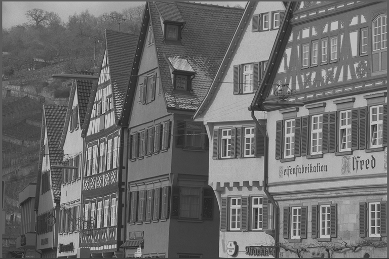
The input image and the enhanced output image should look like this:
|

|
|---|---|
Input Image |
Output Image |