RDF Halo Configuration#
In this tutorial we implement another image enhancement algorithm using the PVA SDK. Unsharp masking is a well-known technique that improves the image contrast along the edges of objects so that they look sharper. The basic idea behind unsharp masking is to boost the intensity of pixels proportional to the difference from their neighbors. The average intensity of neighboring pixels are computed using a 2-D Gaussian weighted averaging kernel.
This example uses a 5-pixel by 5-pixel kernel to realize the blurring and enhancement in a single step, as described in the equation below:
\(I_{out} = I_{in} + c * ( I_{in} - I_{blur} )\)
\(I_{out}\) and \(I_{in}\) are the output and input intensities, respectively.
\(I_{blur}\) is the Gaussian weighted average of the 5x5 pixel neighborhood and \(c\) is the enhancement multiplier.
PVA is very good at filtering operations that involve multiplications and accumulations thanks to its VLIW SIMD architecture, as we see in the upcoming tutorials.
Filtering and convolution operations require access to a sliding window of input data to generate output data. As we have seen in the previous tutorials PVA processes the images in tiles. For each tile, the sliding window overlaps the edge of the tile. Therefore, input data from multiple tiles are needed to generate a single output tile. Halo specifies how much input data should be included from neighboring tiles when processing the current tile. In the case of an \(m x n\) filter kernel, we need \(m/2\) additional pixels from left and right neighbor tiles and \(n/2\) pixels from top and bottom neighbors to form a ‘halo’ around the input tile and generate the output tile. Since our filter is 5x5, the halo in both horizontal and vertical directions are 2 pixels wide. RDF API automatically fetches the tile’s halo using the hardware support from the DMA engine.
In this tutorial we see:
How to configure the halo for the Raster DataFlows.
How to allocate a circular buffer in VMEM for efficient access to halo pixels.
Device Code#
The first step in the device code is to set the tile size and 2-D filter size parameters by including the common header file.
One of the differences in the code compared to the previous tutorial is in the input tile buffer allocation. This time we use the
RDF_CIRCULARhelper macro while declaring the inputTileBufferVMEM.Using a circular buffer means that halo in the first advancement dimension, which is row-major in this example, can be shared between subsequent tiles. Circular buffer layout requires more VMEM space compared to
RDF_DOUBLEorRDF_SINGLEbut may increase the performance.We continue using double layout for the output tile buffer.
Note
The RDF API only supports halo for source data flows (DRAM to VMEM).
#include "../handle_halo_padding_common_params.h"

#include <cupva_device.h>       /* Main device-side header file */
#include <cupva_device_debug.h> /* Header file containing the printf function */

VMEM(A, uint8_t, inputTileBufferVMEM,
     RDF_CIRCULAR(uint8_t, TILE_WIDTH, TILE_HEIGHT, KERNEL_RADIUS_HOR, KERNEL_RADIUS_VER));
VMEM(B, uint8_t, outputTileBufferVMEM, RDF_DOUBLE(uint8_t, TILE_WIDTH, TILE_HEIGHT));
Algorithm-specific VMEM declarations are done for the filter coefficients array and the quantization bit shift amount. These parameters are set in the host-side code. Unlike in the RDF Double Buffering Tutorial from the previous section, we are now using the simpler unified RDF triggering APIs, as we did in the Raster Data Flow (RDF) and Tiles Tutorial from the previous section. Recall that this API provides a consistent triggering API for all VMEM buffer layouts, including circular buffer. To use explicit triggering APIs with circular buffer, user must explicitly complete two tile transfers before accessing data in VMEM. In many cases, a copy from head to tail of the circular buffer is also needed to ensure that contiguous 64B vectors may be loaded. This detail does not need to be considered when using acquire/release APIs.
VMEM(C, int16_t, kernel, KERNEL_WIDTH *KERNEL_HEIGHT);
VMEM(C, uint8_t, quantizationBits);

VMEM(C, int32_t, tileCount);

VMEM_RDF_UNIFIED(A, sourceDataFlowHandler);
VMEM_RDF_UNIFIED(A, destinationDataFlowHandler);
Source and destination buffer offsets are initialized similar to the previous tutorial. The Offset, LinePitch and CircularBufLength values are used in addressing the pixels while loading from and storing to the tile buffers.
CUPVA_VPU_MAIN()
{
    int32_t srcLinePitch      = cupvaRasterDataFlowGetLinePitch(sourceDataFlowHandler);
    int32_t dstLinePitch      = cupvaRasterDataFlowGetLinePitch(destinationDataFlowHandler);
    int32_t srcCircularBufLen = cupvaRasterDataFlowGetCbLen(sourceDataFlowHandler);
The outer tile processing loop is similar to that introduced in Raster Data Flow (RDF) and Tiles Tutorial from the previous section. Combining with the definition of inputTileBufferVMEM using RDF_CIRCULAR, this causes cuPVA to re-use horizontal halo between tiles, leading to less DMA bandwidth needed.
    cupvaRasterDataFlowOpen(sourceDataFlowHandler, &inputTileBufferVMEM[0]);
    cupvaRasterDataFlowOpen(destinationDataFlowHandler, &outputTileBufferVMEM[0]);

    for (int32_t i = 0; i < tileCount; i++)
    {
        uint8_t *inputTile  = (uint8_t *)cupvaRasterDataFlowAcquire(sourceDataFlowHandler);
        uint8_t *outputTile = (uint8_t *)cupvaRasterDataFlowAcquire(destinationDataFlowHandler);
2-D filtering operation is carried out in the inner loop. Note that this tutorial provides a non-optimized reference implementation. Techniques for optimizing the filtering loop to fully utilize the VPU’s capabilities are presented in the upcoming tutorials.
The source pixels in the 5x5 window are multiplied with the kernel coefficients and accumulated. The accumulation result is quantized and clipped to the 0 to 255 intensity range.
Source and destination pixels are addressed by multiplying the row index with the line pitch values. The modulo operation in the source pixel addresses takes care of the wrap-around in circular buffer. In future tutorials we show how this wrap can be handled automatically by the VPU’s address generation hardware.
        int32_t srcOffset = inputTile - &inputTileBufferVMEM[0];
        for (int32_t y = 0; y < TILE_HEIGHT; y++)
        {
            for (int32_t x = 0; x < TILE_WIDTH; x++)
            {
                int32_t outputPixelAccumulator = 0;
                for (int32_t i = 0; i < KERNEL_HEIGHT; i++)
                {
                    for (int32_t j = 0; j < KERNEL_WIDTH; j++)
                    {
                        int16_t sourcePixel =
                            inputTileBufferVMEM[(srcOffset + (y + i) * srcLinePitch + (x + j)) % srcCircularBufLen];
                        int16_t coefficient = kernel[i * KERNEL_WIDTH + j];

                        outputPixelAccumulator += (int32_t)sourcePixel * coefficient;
                    }
                }
                outputPixelAccumulator           = ((outputPixelAccumulator >> (quantizationBits - 1)) + 1) >> 1;
                outputPixelAccumulator           = max(0, min(outputPixelAccumulator, 255));
                outputTile[y * dstLinePitch + x] = outputPixelAccumulator;
            }
        }
Releasing tiles causes the next tiles to be transferred.
        cupvaRasterDataFlowRelease(sourceDataFlowHandler);
        cupvaRasterDataFlowRelease(destinationDataFlowHandler);
    }

    cupvaRasterDataFlowClose(sourceDataFlowHandler);
    cupvaRasterDataFlowClose(destinationDataFlowHandler);
    return 0;
}
Host Code#
This application uses the same input image file and image/tile sizes as the previous tutorial.
Unsharp masking algorithm is implemented using a 5x5 2-D image filter kernel. The filter coefficients are stored in an int16_t array. Since the coefficients sum up to 256, 8-bit right shift is required to quantize the final result to the 1-byte per pixel range.
#include "ImageIO.h"
#include "handle_halo_padding_common_params.h"

#include <cupva_host.hpp> // Main host-side C++-API header file

#include <cupva_platform.h> // Header that includes macros for specifying PVA executables

#include <iostream>

using namespace cupva;

PVA_DECLARE_EXECUTABLE(handle_halo_padding_dev)

namespace {
std::string inputImageName{"low_contrast_kodim08_768x512_grayscale.data"};
std::string outputImageName{"unsharp_masked_kodim08_768x512_grayscale.data"};

constexpr int32_t IMAGE_WIDTH{768};
constexpr int32_t IMAGE_HEIGHT{512};

constexpr int MAX_IMAGE_PATH_LENGTH{320};
char assetsDirectory[MAX_IMAGE_PATH_LENGTH];

constexpr int16_t UNSHARP_MASK_FILTER[KERNEL_WIDTH * KERNEL_HEIGHT] = {-1, -4,  -6,  -4,  -1, //
                                                                       -4, -16, -24, -16, -4, //
                                                                       -6, -24, 476, -26, -6, //
                                                                       -4, -16, -24, -16, -4, //
                                                                       -1, -4,  -6,  -4,  -1};

constexpr uint8_t QUANTIZATION_BITS{8};
} // namespace
Similar to the previous tutorial, the application requires the assets directory path to be passed as an argument to locate the input image file.
int main(int argc, char **argv)
{
    if (GetAssetsDirectory(argc, argv, assetsDirectory, MAX_IMAGE_PATH_LENGTH) != 0)
    {
        return 0;
    }

    try
    {
        Executable exec = Executable::Create(PVA_EXECUTABLE_DATA(handle_halo_padding_dev),
                                             PVA_EXECUTABLE_SIZE(handle_halo_padding_dev));
        CmdProgram prog = CmdProgram::Create(exec);
The algorithm parameters and tile count value are transferred to the device-side process.
        prog["kernel"].set(UNSHARP_MASK_FILTER, KERNEL_WIDTH * KERNEL_HEIGHT);
        prog["quantizationBits"] = QUANTIZATION_BITS;

        const int32_t tileCount = (IMAGE_WIDTH * IMAGE_HEIGHT) / (TILE_WIDTH * TILE_HEIGHT);
        prog["tileCount"]       = tileCount;
Buffers for input and output images are allocated in the DRAM using the
mem::Alloc()API and the input image is loaded.uint8_t *inputImage_d = (uint8_t *)mem::Alloc(IMAGE_WIDTH * IMAGE_HEIGHT * sizeof(uint8_t)); uint8_t *inputImage_h = (uint8_t *)mem::GetHostPointer(inputImage_d); if (ReadImageBuffer(inputImageName.c_str(), assetsDirectory, inputImage_h, IMAGE_WIDTH * IMAGE_HEIGHT) != 0) { mem::Free(inputImage_d); return -1; } uint8_t *outputImage_d = (uint8_t *)mem::Alloc(IMAGE_WIDTH * IMAGE_HEIGHT * sizeof(uint8_t)); uint8_t *outputImage_h = (uint8_t *)mem::GetHostPointer(outputImage_d);
Source and destination data flows are configured very similar to the previous tutorial. The only difference is the
RasterDataFlow::halo()API call during the source data flow setup. RasterDataFlow takes care of fetching halo pixels when the halo size is configured with this API.Some halo pixels can not be filled from the neighbor tiles if the tile is at the borders of the image. RDF uses DMA support to automatically add padding for out of image boundary accesses. User may choose to pad with a constant value or by extending the border pixel values. The default behavior is to pad with value 0.
The choice between boundary pixel extension and constant value applies not only to halo, but also to ordinary pixels within a tile which are out of image bounds. RDF always fills full tiles into VMEM, so if an image has dimensions which are not a multiple of tile dimensions, some of these pixels are either padded or boundary extended depending on the choice made here. Note that halo size can be set to 0 if the application does not require halo but needs to use a non-default padding setting.
        RasterDataFlow &sourceDataFlow = prog.addDataFlowHead<RasterDataFlow>();
        auto sourceDataFlowHandler     = prog["sourceDataFlowHandler"];
        uint8_t *inputTileBufferVMEM   = prog["inputTileBufferVMEM"].ptr<uint8_t>();
        sourceDataFlow.handler(sourceDataFlowHandler)
            .src(inputImage_d, IMAGE_WIDTH, IMAGE_HEIGHT, IMAGE_WIDTH)
            .tileBuffer(inputTileBufferVMEM)
            .tile(TILE_WIDTH, TILE_HEIGHT)
            .halo(KERNEL_RADIUS_HOR, KERNEL_RADIUS_VER);

        RasterDataFlow &destinationDataFlow = prog.addDataFlowHead<RasterDataFlow>();
        auto destinationDataFlowHandler     = prog["destinationDataFlowHandler"];
        uint8_t *outputTileBufferVMEM       = prog["outputTileBufferVMEM"].ptr<uint8_t>();
        destinationDataFlow.handler(destinationDataFlowHandler)
            .tileBuffer(outputTileBufferVMEM)
            .tile(TILE_WIDTH, TILE_HEIGHT)
            .dst(outputImage_d, IMAGE_WIDTH, IMAGE_HEIGHT, IMAGE_WIDTH);

        prog.compileDataFlows();
Similar to the previous tutorial, the CmdProgram is submitted to the stream and output image file is written when the fence expires.
        SyncObj sync = SyncObj::Create();
        Fence fence{sync};
        CmdRequestFences rf{fence};
        Stream stream = Stream::Create();

        CmdStatus status[2];
        stream.submit({&prog, &rf}, status);

        fence.wait();
        cupva::Error statusCode = CheckCommandStatus(status[0]);
        if (statusCode != Error::None)
        {
            std::cout << "VPU Program returned an Error Code: " << (int32_t)statusCode << std::endl;
        }
        else
        {
            if (WriteImageBuffer(outputImageName.c_str(), ".", outputImage_h, IMAGE_WIDTH * IMAGE_HEIGHT) != 0)
            {
                mem::Free(inputImage_d);
                mem::Free(outputImage_d);
                return -1;
            }
        }
        mem::Free(inputImage_d);
        mem::Free(outputImage_d);
    }
    catch (cupva::Exception const &e)
    {
        std::cout << "Caught a cuPVA exception with message: " << e.what() << std::endl;
        return 1;
    }
    return 0;
}
This application uses the same input image file and image/tile sizes as the previous tutorial.
Unsharp masking algorithm is implemented using a 5x5 2-D image filter kernel. The filter coefficients are stored in an int16_t array. Since the coefficients sum up to 256, 8-bit right shift is required to quantize the final result to the 1-byte per pixel range.
#include "ImageIO.h"
#include "handle_halo_padding_common_params.h"

#include <cupva_host.h>
#include <cupva_platform.h>
#include <stdio.h>

#define CHECK_ERROR_GOTO(__v, __e, __l)                  \
    __e = __v;                                           \
    if (__e != CUPVA_ERROR_NONE)                         \
    {                                                    \
        printf("cuPVA C-API return error: %d\n", (__v)); \
        goto __l;                                        \
    }

PVA_DECLARE_EXECUTABLE(handle_halo_padding_dev)

#define INPUT_IMAGE_NAME "low_contrast_kodim08_768x512_grayscale.data"
#define OUTPUT_IMAGE_NAME "unsharp_masked_kodim08_768x512_grayscale.data"

#define IMAGE_WIDTH 768
#define IMAGE_HEIGHT 512

#define MAX_IMAGE_PATH_LENGTH 320
char assetsDirectory[MAX_IMAGE_PATH_LENGTH];

#define QUANTIZATION_BITS 8
int16_t UNSHARP_MASK_FILTER[KERNEL_WIDTH * KERNEL_HEIGHT] = {-1, -4,  -6,  -4,  -1, //
                                                             -4, -16, -24, -16, -4, //
                                                             -6, -24, 476, -26, -6, //
                                                             -4, -16, -24, -16, -4, //
                                                             -1, -4,  -6,  -4,  -1};
Similar to the previous tutorial, the application requires the assets directory path to be passed as an argument to locate the input image file.
int main(int argc, char **argv)
{
    int32_t err = 0;

    if (GetAssetsDirectory(argc, argv, assetsDirectory, MAX_IMAGE_PATH_LENGTH) != 0)
    {
        return 0;
    }

    cupvaExecutable_t exec;
    CHECK_ERROR_GOTO(CupvaExecutableCreate(&exec, PVA_EXECUTABLE_DATA(handle_halo_padding_dev),
                                           PVA_EXECUTABLE_SIZE(handle_halo_padding_dev)),
                     err, ExecutableCreateFailed);
    cupvaCmd_t prog;
    CHECK_ERROR_GOTO(CupvaCmdProgramCreate(&prog, exec), err, CmdProgramCreateFailed);
The algorithm parameters and tile count value are transferred to the device-side process.
cupvaParameter_t param; CHECK_ERROR_GOTO(CupvaCmdProgramGetParameter(&prog, ¶m, "kernel"), err, CmdProgramCreateFailed); CHECK_ERROR_GOTO(CupvaParameterSetValueArray(¶m, (uint8_t *)UNSHARP_MASK_FILTER, sizeof(UNSHARP_MASK_FILTER)), err, CmdProgramCreateFailed); const uint8_t quantizationBits = QUANTIZATION_BITS; CHECK_ERROR_GOTO(CupvaCmdProgramGetParameter(&prog, ¶m, "quantizationBits"), err, CmdProgramCreateFailed); CHECK_ERROR_GOTO(CupvaParameterSetValueScalar(¶m, &quantizationBits, sizeof(uint8_t)), err, CmdProgramCreateFailed); const int32_t tileCount = (IMAGE_WIDTH * IMAGE_HEIGHT) / (TILE_WIDTH * TILE_HEIGHT); CHECK_ERROR_GOTO(CupvaCmdProgramGetParameter(&prog, ¶m, "tileCount"), err, CmdProgramCreateFailed); CHECK_ERROR_GOTO(CupvaParameterSetValueScalar(¶m, &tileCount, sizeof(int32_t)), err, CmdProgramCreateFailed);
Buffers for input and output images are allocated in the DRAM using the CupvaMemAlloc() API and the input image is loaded.
    uint8_t *inputImage_d = NULL;
    CHECK_ERROR_GOTO(CupvaMemAlloc((void **)&inputImage_d, IMAGE_WIDTH * IMAGE_HEIGHT * sizeof(uint8_t),
                                   CUPVA_READ_WRITE, CUPVA_ALLOC_DRAM),
                     err, MemAllocFailed);

    uint8_t *inputImage_h = NULL;
    CHECK_ERROR_GOTO(CupvaMemGetHostPointer((void **)&inputImage_h, (void *)inputImage_d), err, MemAllocFailed);

    if (ReadImageBuffer(INPUT_IMAGE_NAME, assetsDirectory, inputImage_h, IMAGE_WIDTH * IMAGE_HEIGHT) != 0)
    {
        err = -1;
        goto MemAllocFailed;
    }

    uint8_t *outputImage_d = NULL;
    CHECK_ERROR_GOTO(CupvaMemAlloc((void **)&outputImage_d, IMAGE_WIDTH * IMAGE_HEIGHT * sizeof(uint8_t),
                                   CUPVA_READ_WRITE, CUPVA_ALLOC_DRAM),
                     err, MemAllocFailed);

    uint8_t *outputImage_h = NULL;
    CHECK_ERROR_GOTO(CupvaMemGetHostPointer((void **)&outputImage_h, (void *)outputImage_d), err, MemAllocFailed);
Source and destination data flows are configured very similar to the previous tutorial. The only difference is that the haloX and haloY properties of the data flow configuration structure are set. RasterDataFlow takes care of fetching halo pixels when non-zero halo dimensions are provided.
Some halo pixels can not be filled from the neighbor tiles if the tile is at the borders of the image. RDF uses DMA support to automatically add padding for out of image boundary accesses. User may choose to pad with a constant value or by extending the border pixel values. The default behavior is to pad with value 0.
The choice between boundary pixel extension and constant value applies not only to halo, but also to ordinary pixels within a tile which are out of image bounds. RDF always fills full tiles into VMEM, so if an image has dimensions which are not a multiple of tile dimensions, some of these pixels are either padded or boundary extended depending on the choice made here.
cupvaDataFlow_t sourceDataFlow; CHECK_ERROR_GOTO(CupvaCmdProgramAddDataFlowHead(&prog, &sourceDataFlow, CUPVA_RASTER_DATAFLOW, 0, 1.0F), err, SyncObjCreateFailed); cupvaParameter_t sourceDataFlowHandler; CHECK_ERROR_GOTO(CupvaCmdProgramGetParameter(&prog, &sourceDataFlowHandler, "sourceDataFlowHandler"), err, SyncObjCreateFailed); uint8_t *inputTileBufferVMEM; CHECK_ERROR_GOTO(CupvaCmdProgramGetParameter(&prog, ¶m, "inputTileBufferVMEM"), err, SyncObjCreateFailed); CHECK_ERROR_GOTO(CupvaParameterGetDevicePointer(¶m, (void const **)&inputTileBufferVMEM), err, SyncObjCreateFailed); cupvaRasterDataFlowParams_t sourceDataFlowParams = {.handler = &sourceDataFlowHandler, .ptrSrc = inputImage_d, .linePitchSrc = IMAGE_WIDTH, .srcWidth = IMAGE_WIDTH, .srcHeight = IMAGE_HEIGHT, .ptrTileBuffer = inputTileBufferVMEM, .tileWidth = TILE_WIDTH, .tileHeight = TILE_HEIGHT, .bpp = sizeof(uint8_t), .haloX = KERNEL_RADIUS_HOR, .haloY = KERNEL_RADIUS_VER}; CHECK_ERROR_GOTO(CupvaRasterDataFlowSetParams(sourceDataFlow, &sourceDataFlowParams), err, SyncObjCreateFailed); cupvaDataFlow_t destinationDataFlow; CHECK_ERROR_GOTO(CupvaCmdProgramAddDataFlowHead(&prog, &destinationDataFlow, CUPVA_RASTER_DATAFLOW, 0, 1.0F), err, SyncObjCreateFailed); cupvaParameter_t destinationDataFlowHandler; CHECK_ERROR_GOTO(CupvaCmdProgramGetParameter(&prog, &destinationDataFlowHandler, "destinationDataFlowHandler"), err, SyncObjCreateFailed); CHECK_ERROR_GOTO(CupvaCmdProgramGetParameter(&prog, ¶m, "outputTileBufferVMEM"), err, SyncObjCreateFailed); uint8_t *outputTileBufferVMEM; CHECK_ERROR_GOTO(CupvaParameterGetDevicePointer(¶m, (void const **)&outputTileBufferVMEM), err, SyncObjCreateFailed); cupvaRasterDataFlowParams_t destinationDataFlowParams = {.handler = &destinationDataFlowHandler, .ptrDst = outputImage_d, .linePitchDst = IMAGE_WIDTH, .dstWidth = IMAGE_WIDTH, .dstHeight = IMAGE_HEIGHT, .ptrTileBuffer = outputTileBufferVMEM, .tileWidth = TILE_WIDTH, .tileHeight = TILE_HEIGHT, .bpp = sizeof(uint8_t)}; CHECK_ERROR_GOTO(CupvaRasterDataFlowSetParams(destinationDataFlow, &destinationDataFlowParams), err, SyncObjCreateFailed); CHECK_ERROR_GOTO(CupvaCmdProgramCompileDataFlows(&prog), err, SyncObjCreateFailed);
Similar to the previous tutorial, the CmdProgram is submitted to the stream and output image file is written when the fence expires.
    cupvaSyncObj_t sync;
    CHECK_ERROR_GOTO(CupvaSyncObjCreate(&sync, false, CUPVA_SIGNALER_WAITER, CUPVA_SYNC_YIELD), err,
                     SyncObjCreateFailed);

    cupvaFence_t fence;
    CHECK_ERROR_GOTO(CupvaFenceInit(&fence, sync), err, StreamCreateFailed);

    cupvaCmd_t rf;
    CHECK_ERROR_GOTO(CupvaCmdRequestFencesInit(&rf, &fence, 1), err, StreamCreateFailed);

    cupvaStream_t stream;
    CHECK_ERROR_GOTO(CupvaStreamCreate(&stream, CUPVA_PVA0, CUPVA_VPU_ANY), err, StreamCreateFailed);

    cupvaCmd_t const *cmds[2]  = {&prog, &rf};
    cupvaCmdStatus_t status[2] = {NULL, NULL};
    CHECK_ERROR_GOTO(CupvaStreamSubmit(stream, cmds, status, 2, CUPVA_IN_ORDER, -1, -1), err, DeAllocateAllResources);

    bool waitSuccess;
    CHECK_ERROR_GOTO(CupvaFenceWait(&fence, -1, &waitSuccess), err, DeAllocateAllResources);

    cupvaError_t statusCode = CUPVA_ERROR_NONE;
    CupvaCheckCommandStatus(status[0], &statusCode);
    if (statusCode != CUPVA_ERROR_NONE)
    {
        printf("VPU Program returned an Error Code: %d\n", (int32_t)statusCode);
    }
    else
    {
        if (WriteImageBuffer(OUTPUT_IMAGE_NAME, ".", outputImage_h, IMAGE_WIDTH * IMAGE_HEIGHT) != 0)
        {
            err = -1;
            goto DeAllocateAllResources;
        }
    }

DeAllocateAllResources: /* clean up all allocated resources */
    CupvaStreamDestroy(stream);
StreamCreateFailed: /* clean up resources allocated prior to StreamCreate */
    CupvaSyncObjDestroy(sync);
SyncObjCreateFailed: /* clean up resources allocated prior to SyncObjCreate */
MemAllocFailed:      /* clean up resources allocated prior to MemAlloc */
    CupvaMemFree(inputImage_d);
    CupvaMemFree(outputImage_d);
    CupvaCmdDestroy(&prog);
CmdProgramCreateFailed: /* clean up resources allocated prior to CmdProgramCreate */
    CupvaExecutableDestroy(exec);
ExecutableCreateFailed: /* clean up resources allocated prior to ExecutableCreate */
    return err;
}
Output#
The path to the Tutorial assets directory containing the input image file “low-contrast-kodim08-768x512-grayscale.data” should be provided as an argument.
Enhanced image output file “unsharp-masked-kodim08-768x512-grayscale.data” is written to the current working directory.
$ ./handle_halo_padding_cpp -a <Tutorial Assets Directory Path>
Read 393216 bytes from <Tutorial Assets Directory Path>/low-contrast-kodim08-768x512-grayscale.data
Wrote 393216 bytes to ./unsharp-masked-kodim08-768x512-grayscale.data
$ ./handle_halo_padding_c -a <Tutorial Assets Directory Path>
Read 393216 bytes from <Tutorial Assets Directory Path>/low-contrast-kodim08-768x512-grayscale.data
Wrote 393216 bytes to ./unsharp-masked-kodim08-768x512-grayscale.data
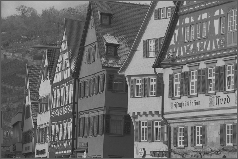
The input image and the enhanced output image should look like this:
|

|
|---|---|
Input Image |
Output Image |