RDF Double Buffering#
This tutorial tweaks the contrast stretching application to make it run faster. Double (ping-pong) buffering approach is applied in the device side. Using double buffer layout enables VPU to load, process and store data in parallel with the DMA transfers. Parallel operation helps to hide the memory access latency if the application is compute bound. Similarly, computational delay can be hidden if the algorithm is memory bound.
The below figure demonstrates an example timing diagram where double buffering improves the latency of a memory-bound algorithm.
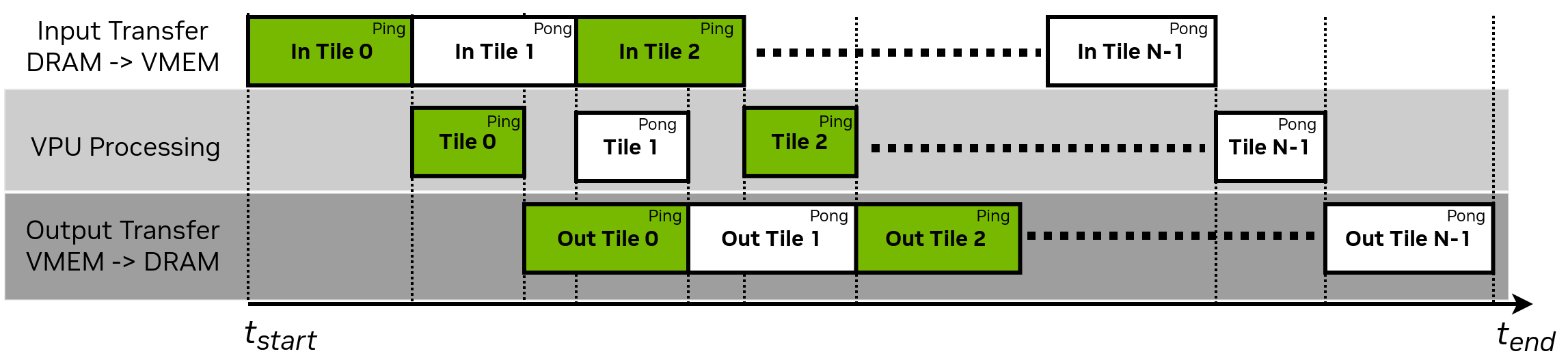
RDF Double Buffering - Time Diagram#
In this tutorial we introduce:
How to allocate VMEM tile buffer with double layout.
How to use explicit RDF tile triggering APIs, rather than implicit acquire/release semantics.
The host code remains same as the Raster Data Flow (RDF) and Tiles Tutorial, so we simply present the device code in this tutorial.
Device Code#
The RDF_DOUBLE helper macro can be used to calculate the minimum buffer length (in pixels) required to support double buffer layout for RasterDataFlow. Double layout uses more VMEM space but allows pipelining data read/writes with DMA accesses.
Here we allocate enough VMEM buffer to enable RDF to use double layout for both input and output tile buffers. TILE_WIDTH and TILE_HEIGHT parameters are declared in the common header file as in Raster Data Flow (RDF) and Tiles Tutorial.
Making the modification of RDF_SINGLE->RDF_DOUBLE is sufficient to achieve the objective and performance gains of double buffering. The buffering layout for RDF is completely determined by the size of the available VMEM buffer. Simply by providing a large enough buffer to use double buffering, cuPVA takes advantage of this without any further code modifications, provided the
cupvaRasterDataFlowAcquire/ReleaseAPIs are used for triggering.In some cases, users require additional control over when a DMA channel is active. For this reason, cuPVA allows another form of interacting with RDFs using
cupvaRasterDataFlowTrig/Sync. This is a lower level form of triggering which is abstracted bycupvaRasterDataFlowAcquire/Release. The main difference forcupvaRasterDataFlowTrig/Syncis that the code must be written to reflect the buffering mode. This is the focus of the remainder of this tutorial.#include "../double_buffering_common_params.h" #include <cupva_device.h> /* Main device-side header file */ VMEM(A, uint8_t, inputTileBufferVMEM, RDF_DOUBLE(uint8_t, TILE_WIDTH, TILE_HEIGHT)); VMEM(B, uint8_t, outputTileBufferVMEM, RDF_DOUBLE(uint8_t, TILE_WIDTH, TILE_HEIGHT));
The parameter setup stages leading to the main processing loop are similar to Raster Data Flow (RDF) and Tiles Tutorial. However, we now declare
sourceDataFlowHandleranddestinationDataFlowHandlerin a slightly different fashion. In Raster Data Flow (RDF) and Tiles Tutorial, we used VMEM_RDF_UNIFIED which results in a structure of type UnifiedRDFHandler, compatible withcupvaRasterDataFlowOpen/Close/Acquire/Release. Here we instead declare a RasterDataFlowHandler, indicating we plan to usecupvaRasterDataFlowTrig/Syncinstead.VMEM(C, int32_t, tileCount); VMEM(A, RasterDataFlowHandler, sourceDataFlowHandler); VMEM(B, RasterDataFlowHandler, destinationDataFlowHandler); VMEM(C, uint8_t, algorithmParams, sizeof(ContrastStretchParams)); CUPVA_VPU_MAIN() { ContrastStretchParams *params = (ContrastStretchParams *)algorithmParams; uint8_t inputDynamicRange = params->inputHighPixelValue - params->inputLowPixelValue; uint8_t outputDynamicRange = params->outputHighPixelValue - params->outputLowPixelValue; int32_t outputPixelValue; int32_t srcLinePitch = cupvaRasterDataFlowGetLinePitch(sourceDataFlowHandler); int32_t dstLinePitch = cupvaRasterDataFlowGetLinePitch(destinationDataFlowHandler);
We define two variables to track the read and write offsets within the ping-pong tile buffers. Offsets are initialized to 0 for both buffers.
    int32_t srcOffset = 0;
    int32_t dstOffset = 0;
Here we use explicit RDF triggering to achieve ping-pong buffering pattern. Ping buffer is filled with the first tile using the Trig and Sync calls. Subsequently, the VPU triggers the transfer of the second tile and proceeds to the pixel processing loop without waiting for its completion. Second tile is automatically transferred to the pong buffer by the RDF. Also note that, the number of source
cupvaRasterDataFlowTrig()calls is one more than the tileCount. The lastcupvaRasterDataFlowTrig()call immediately returns because there is no more tiles left in the RDF. This behavior eliminates the need for conditional trigger statements and simplifies the outer tile loop.cupvaRasterDataFlowTrig(sourceDataFlowHandler); for (int32_t i = 0; i < tileCount; i++) { cupvaRasterDataFlowSync(sourceDataFlowHandler); cupvaRasterDataFlowTrig(sourceDataFlowHandler);
The inner pixel processing loop is similar to the previous tutorial. The only difference is that the input pixels are now loaded with a ping/pong buffer offset. A similar pixel offset is also applied when storing the resulting intensity values to the output tile buffer.
        for (int32_t i = 0; i < TILE_HEIGHT; i++)
        {
            for (int32_t j = 0; j < TILE_WIDTH; j++)
            {
                outputPixelValue = outputDynamicRange *
                                   (inputTileBufferVMEM[i * srcLinePitch + j + srcOffset] - params->inputLowPixelValue);
                outputPixelValue /= inputDynamicRange;
                outputPixelValue += params->outputLowPixelValue;
                outputPixelValue =
                    max(params->outputLowPixelValue, min(outputPixelValue, params->outputHighPixelValue));
                outputTileBufferVMEM[i * dstLinePitch + j + dstOffset] = (uint8_t)outputPixelValue;
            }
        }
cuPVA provides
cupvaRasterDataFlowGetOffset()API to calculate the pixel offset for the next tile. Source and destination offsets should be updated before starting to process the next tile.srcOffset = cupvaRasterDataFlowGetOffset(sourceDataFlowHandler, srcOffset); dstOffset = cupvaRasterDataFlowGetOffset(destinationDataFlowHandler, dstOffset);
The destinationDataFlow that is defined to transfer algorithm output to the DRAM also makes use of the double buffer layout. VPU triggers the transfer of first output tile but does not block the VPU process. The Sync call for the first tile is at the end of the second tile iteration. Transfer occurs in parallel with the input DMA transfer and VPU processing. Note that the first
cupvaRasterDataFlowSync()call does not have a matching priorcupvaRasterDataFlowTrig()call. Therefore this firstcupvaRasterDataFlowSync()call immediately returns. Similar to source DataFlow, this behavior is used to simplify the outer loop code.cupvaRasterDataFlowSync(destinationDataFlowHandler); cupvaRasterDataFlowTrig(destinationDataFlowHandler); }
We make sure the last tile is written back to DRAM before returning from the main.
    cupvaRasterDataFlowSync(destinationDataFlowHandler);
    return 0;
}