Region of Interest (ROI) Gather via GatherScatter Dataflow (GSDF)#
Beginning here, for the next 4 tutorials, we introduce an additional set of cuPVA APIs and PVA programming concepts that culminates into an optimized implementation of an ROI Align Layer from a Region Proposal Network (RPN). The RPN’s purpose is to provide a list of candidate objects of interest for subsequent analysis by a segmentation, detection, and/or object classification neural network. The ROI Align layer’s role in the RPN is to extract the feature map data corresponding to each ROI in the list and output a fixed-sized feature vector. This basic flow of operations is shown in the following figure:
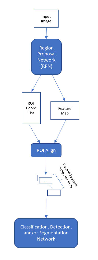
The fixed-sized feature vectors produced by the ROI Align Layer are fed into another neural network for the purposes of classification, detection, and or segmentation. The basics of the algorithm are described in this tutorial. For additional detail, refer to He et. al’s paper titled “Mask R-CNN” which goes in-depth into the entire algorithm (https://arxiv.org/pdf/1703.06870v3.pdf).
The input to the ROI Align layer is a FW x FH x C “feature map” and a list of ROI coordinates
Since the ROI coordinates refer to the dimensions of the original input image, they must be scaled down by a factor of “k” so that the correct feature map data is picked up by the ROI Align layer.
Note that “k” is floating-point, as the ROI Align layer supports pulling feature map data at fractional offsets via bilinear interpolation (support for fractional offset has been shown to improve the accuracy of proposals). The following figure illustrates the basic concept behind the ROI Align Layer.
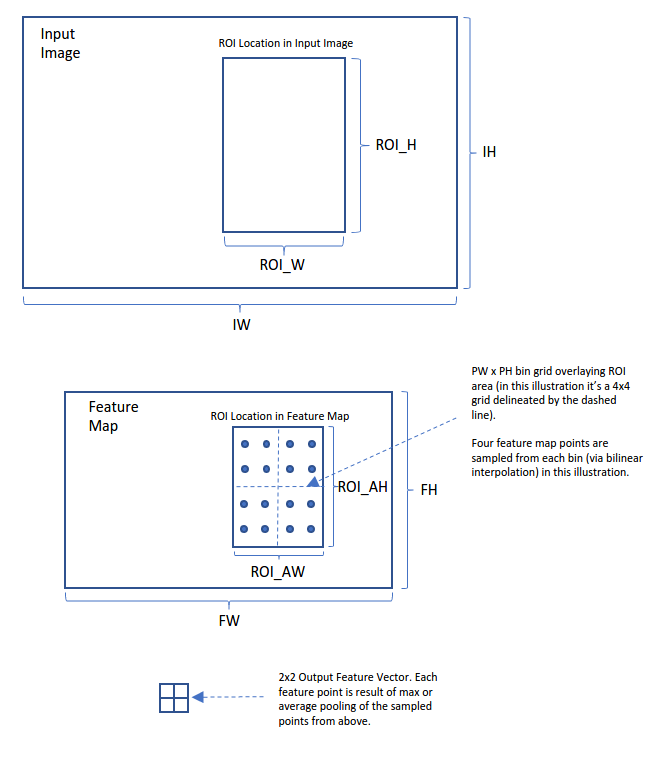
For each ROI produced by the RPN, its corresponding location in the feature map is sub-divided into a PW x PH grid of bins. In this illustration, from each bin, four points are sampled and processed to produce a point in the output feature vector. The output feature vector is the same fixed-size (PW x PH) for each ROI.
Since the location of the ROI candidates are unknown at compile time, the GatherScatter Data Flow (GSDF) APIs are used so that we can setup DMA fetches of the ROI’s feature map data at runtime. This tutorial, ROI Gather using GSDF Tutorial, introduces the concept of Raster & GatherScatter DataFlows (RDF & GSDF) via a simple ROI gather example.
Since the ROI Align layer supports retrieval of data at fractional coordinate offsets, bilinear interpolation is used to calculate the data at these offsets. The PVA hardware contains support for accelerating bilinear interpolation operations via its Decoupled Lookup Table Unit (DLUT). Utilizing the DLUT unit to sample points from the feature map is also discussed in this tutorial.
Sampler APIs Tutorial takes the GSDF and DLUT concepts and apply them to creating a functional ROI Align layer implementation.
ROI Align Layer on VPU Tutorial completes the ROI Align tutorial series by demonstrating how to optimize the flow of operations (i.e. apply ping/pong buffering and overlapping DLUT acceleration with VPU processing and DMA transfers)
Device Code#
The following steps describe how to setup the device-side code for triggering the transfer of ROIs to/from DRAM and VMEM using an ROI coordinate list provided by the host.
VMEM buffers are declared for the transferred ROIs and coordinates list.
VMEM(B, int16_t, roi_vmem_buf, GATHER_MAX_ROI_SIZE);
VMEM(C, Point2D, coords, RDF_SINGLE(Point2D, NUM_ROIS, 1));
The handler for the GSDF open, close, trig, and sync APIs, is declared as follows:
VMEM_GSDF_HANDLER(A, gsdf_handler, NUM_TILES_PER_TRIGGER);
The RDF and SQDF handlers used for checking completion of the coordinate transfer, and for triggering the transfer of the output ROI, are declared here.
VMEM_RDF_UNIFIED(A, coords_trig);
VMEM_SEQDF_HANDLER(A, roi_out_trig);
GatherScatter Dataflow (GSDF) APIs facilitate transfers of data with addresses determined at runtime. To use the GSDF APIs, we must first open the dataflow object for initialization. This initializes a buffer space in VMEM which is used to store the runtime configurations of the transfer. We initialize this buffer space with the width and height of the ROI tiles, and the destination VMEM address of the ROIs as follows:
cupvaGSDFOpen(gsdf_handler, &roi_vmem_buf[0], GATHER_ROI_W, GATHER_ROI_H);
We now enter the loop to process each ROI in the coordinates list:
    for (int32_t i = 0; i < NUM_ROIS; i++)
    {
Since the horizontal (x) and vertical (y) coordinates are not known at compile time, we pass the x/y coordinates of the ROI patch to the cupvaGSDFUpdateTiles API for each iteration of the loop. This enables the host application to update the transfer addresses during runtime.
cupvaGSDFUpdateTiles(gsdf_handler, &x, &y, NUM_TILES_PER_TRIGGER);
We trigger the transfer of the ROI from the source image in DRAM to the VMEM destination buffer and wait for its completion.
        cupvaGSDFTrig(gsdf_handler);
        cupvaGSDFSync(gsdf_handler);
We now trigger the transfer of the ROI from VMEM to its destination buffer in DRAM. The destination buffer in DRAM contains all the fetched ROIs concatenated contiguously in memory.
        cupvaSQDFTrig(roi_out_trig);
        cupvaSQDFSync(roi_out_trig);
Once all of the ROI batches have been processed the GSDF stream is closed as follows:
    }

    cupvaGSDFClose(gsdf_handler);
Host Code#
This example uses a randomly generated input image (in DRAM) as the source for the ROIs. This image is created as follows:
        GatherTaskParams params;
        params.dparams.input_w = GATHER_IMAGE_WIDTH;
        params.dparams.input_p = GATHER_IMAGE_WIDTH;
        params.dparams.input_h = GATHER_IMAGE_HEIGHT;

        uint16_t *input_image_d =
            (uint16_t *)mem::Alloc(params.dparams.input_h * params.dparams.input_w * sizeof(uint16_t));
        uint16_t *input_image_h = (uint16_t *)mem::GetHostPointer(input_image_d);
        params.input_image_d    = input_image_d;

        srand(96);
        for (int y = 0; y < params.dparams.input_h; y++)
        {
            for (int x = 0; x < params.dparams.input_w; x++)
            {
                input_image_h[y * params.dparams.input_w + x] = rand() % UINT16_MAX;
            }
        }
From this image we gather ROIs and transfer them to VMEM via the cuPVA GatherScatter DataFlow (GSDF) APIs. Each ROI is then transferred to an output buffer (in DRAM) via the cuPVA Raster DataFlow (RDF) APIs.
We allocate memory in DRAM to store the top-left (x,y) coordinates of each ROI to be fetched.
        params.dparams.num_rois = NUM_ROIS;
        params.dparams.roi_h    = GATHER_ROI_H;
        params.dparams.roi_w    = GATHER_ROI_W;

        Point2D *coords_d = (Point2D *)mem::Alloc(params.dparams.num_rois * sizeof(Point2D));
        Point2D *coords_h = (Point2D *)mem::GetHostPointer(coords_d);

        for (int i = 0; i < params.dparams.num_rois; i++)
        {
            coords_h[i].x = rand() % (params.dparams.input_w - params.dparams.roi_w);
            coords_h[i].y = rand() % (params.dparams.input_h - params.dparams.roi_h);
        }
        params.coords_d = coords_d;
The ROI coordinates have been randomly generated for this example.
We allocate memory in DRAM to store the concatenated set of ROIs fetched from the input image.
        uint16_t *output_rois_d = (uint16_t *)mem::Alloc(params.dparams.num_rois * params.dparams.roi_h *
                                                         params.dparams.roi_w * sizeof(uint16_t));
        uint16_t *output_rois_h = (uint16_t *)mem::GetHostPointer(output_rois_d);

        memset(output_rois_h, 0,
               params.dparams.num_rois * params.dparams.roi_h * params.dparams.roi_w * sizeof(int16_t));

        params.output_rois_d = output_rois_d;
Syncpoints and stream objects are created.
        SyncObj sync = SyncObj::Create(true);
        Fence fence{sync};
        CmdRequestFences f{fence};
Stream s = Stream::Create(PVA0, VPU0);
The Executable and CmdProgram objects are created similar to the previous tutorials.
auto prog = CmdProgram::Create(exec);
Here we get the VMEM buffer pointer that the ROI data is transferred to. This is used as a source parameter for the output RDF and as a destination for the input GSDF.
int16_t *roi_vmem_buf = prog["roi_vmem_buf"].ptr<int16_t>();
RDFs are used to describe pre-determined data transfer patterns. In the following code, the RDF is setup to bring in the complete set of coordinates into VMEM on a single transfer. Be aware that for this transfer there is no handler declared. This implies that the transfer is not triggered; hence, the transfer begins as soon as the program starts. This is an added optimization which can allow a transfer to begin without the overhead of waiting for the VPU to trigger it. We link a dummy transfer to this so that we can check for the transfer completion before using its data.
    auto coords_trig            = prog["coords_trig"];
    Point2D *coords_v           = prog["coords"].ptr<Point2D>();
    RasterDataFlow &coordsInput = prog.addDataFlowHead<RasterDataFlow>();
    coordsInput.handler(coords_trig)
        .src(params.coords_d, params.dparams.num_rois, 1, params.dparams.num_rois)
        .tileBuffer(coords_v)
        .tile(params.dparams.num_rois, 1);
In a real application, the location of the ROIs is not known at compile time. Therefore, we must use the GSDF APIs as they facilitate setting src/dst addresses of DMA transfers at runtime. To use the GSDF APIs we first declare the GSDF head.
GatherScatterDataFlow &inputDataFlow = prog.addDataFlowHead<GatherScatterDataFlow>();
We declare the GSDF handler here.
auto gsdf_handler = prog["gsdf_handler"];
We now set the basic parameters of the GSDF.
    inputDataFlow.handler(gsdf_handler)
        .numTilesPerTrigger(NUM_TILES_PER_TRIGGER)
        .src(params.input_image_d, params.dparams.input_w, params.dparams.input_h, params.dparams.input_p)
        .tile(params.dparams.roi_w, params.dparams.roi_h);
numTilesPerTriggeris set to one, which means each GSDF trigger transfers one ROI tile. We set the “src” parameter to be the origin of the input image in DRAM. Additionally, the dimensions of the source image frame and destination tile are set as parameters of the GSDF transfer. The location of the source image patch to be transferred is updated dynamically during runtime.We configure a SQDF DataFlow for transferring the ROIs from VMEM to DRAM.
    auto roi_out_trig            = prog["roi_out_trig"];
    SequenceDataFlow &outputStream = prog.addDataFlowHead<SequenceDataFlow>().handler(roi_out_trig);

    int tile_offset = params.dparams.roi_h * params.dparams.roi_w;

    outputStream.addTransfer()
        .tile(params.dparams.roi_w * sizeof(int16_t), params.dparams.roi_h)
        .src(roi_vmem_buf, params.dparams.roi_w * sizeof(int16_t))
        .srcDim1(params.dparams.num_rois, 0)
        .dst(params.output_rois_d, params.dparams.roi_w * sizeof(int16_t))
        .dstDim1(params.dparams.num_rois, tile_offset * sizeof(int16_t))
        .mode(TransferModeType::TILE);
The final output is each ROI concatenated contiguously in the DRAM.
The dataflows are now ready to be compiled on the host, a required step as mentioned in previous tutorials.
prog.compileDataFlows();
The program is submitted to the VPU and waited for completion here.
s.submit({&prog, &f});
fence.wait();
We verify the output with the following verification check.
        int err = 0;
        for (int n = 0; n < params.dparams.num_rois; n++)
        {
            uint16_t *src_base = input_image_h + coords_h[n].y * params.dparams.input_p + coords_h[n].x;
            uint16_t *dst_base = output_rois_h + params.dparams.roi_h * params.dparams.roi_w * n;
            for (int h = 0; h < params.dparams.roi_h; h++)
            {
                uint16_t *src_base_line = src_base + h * params.dparams.input_w;
                uint16_t *dst_base_line = dst_base + h * params.dparams.roi_w;
                for (int w = 0; w < params.dparams.roi_w; w++)
                {
                    uint16_t srcval = src_base_line[w];
                    uint16_t dstval = dst_base_line[w];
                    if (srcval != dstval)
                    {
                        printf("Mismatch! N: %d H: %d W: %d, Expect: %d, Got: %d\n", n, h, w, srcval, dstval);
                        printf("Coords used for this patch were y:%d, x:%d\n", coords_h[n].y, coords_h[n].x);
                        err = 1;
                        goto end;
                    }
                }
            }
        }
We then delete the allocated resources for cleanup.
        mem::Free(input_image_d);
        mem::Free(output_rois_d);
        mem::Free(coords_d);
The tutorial code is run on the command-line as follows:
$ ./gatherscatter_data_flow_cppYou see “Test Pass (64 ROIs Fetched)” reported upon successful execution of the code.
This example uses a randomly generated input image (in DRAM) as the source for the ROIs. This image is created as follows:
    GatherTaskParams gatherParamsDevice, gatherParamsHost;
    gatherParamsDevice.dparams.input_w = GATHER_IMAGE_WIDTH;
    gatherParamsDevice.dparams.input_p = GATHER_IMAGE_WIDTH;
    gatherParamsDevice.dparams.input_h = GATHER_IMAGE_HEIGHT;

    uint16_t *input_image_d, *input_image_h;

    CHECK_ERROR_GOTO(
        CupvaMemAlloc((void **)&input_image_d,
                      (gatherParamsDevice.dparams.input_w * gatherParamsDevice.dparams.input_h) * sizeof(uint16_t),
                      CUPVA_READ_WRITE, CUPVA_ALLOC_DRAM),
        err, MemAllocFailed);
    CHECK_ERROR_GOTO(CupvaMemGetHostPointer((void **)&input_image_h, input_image_d), err, MemAllocFailed);
    gatherParamsDevice.input_image_d = input_image_d;

    srand(96);
    for (int y = 0; y < gatherParamsDevice.dparams.input_h; y++)
    {
        for (int x = 0; x < gatherParamsDevice.dparams.input_w; x++)
        {
            input_image_h[y * gatherParamsDevice.dparams.input_w + x] = rand() % UINT16_MAX;
        }
    }
From this image we gather ROIs and transfer them to VMEM via the cuPVA GatherScatter DataFlow (GSDF) APIs. Each ROI is then transferred to an output buffer (in DRAM) via the cuPVA Raster DataFlow (RDF) APIs.
We allocate memory in DRAM to store the top-left (x,y) coordinates of each ROI to be fetched.
    gatherParamsDevice.dparams.num_rois = NUM_ROIS;
    gatherParamsDevice.dparams.roi_h    = GATHER_ROI_H;
    gatherParamsDevice.dparams.roi_w    = GATHER_ROI_W;

    CHECK_ERROR_GOTO(
        CupvaMemAlloc((void **)&gatherParamsDevice.coords_d, (gatherParamsDevice.dparams.num_rois * sizeof(Point2D)),
                      CUPVA_READ_WRITE, CUPVA_ALLOC_DRAM),
        err, MemAllocFailed);

    CHECK_ERROR_GOTO(CupvaMemGetHostPointer((void **)&gatherParamsHost.coords_d, gatherParamsDevice.coords_d), err,
                     MemAllocFailed);
    Point2D *coords_h = (Point2D *)gatherParamsHost.coords_d;
    for (int i = 0; i < gatherParamsDevice.dparams.num_rois; i++)
    {
        coords_h[i].x = rand() % (gatherParamsDevice.dparams.input_w - gatherParamsDevice.dparams.roi_w);
        coords_h[i].y = rand() % (gatherParamsDevice.dparams.input_h - gatherParamsDevice.dparams.roi_h);
    }
The ROI coordinates have been randomly generated for this example.
We allocate memory in DRAM to store the concatenated set of ROIs fetched from the input image.
    uint16_t *output_rois_d, *output_rois_h;

    CHECK_ERROR_GOTO(CupvaMemAlloc((void **)&output_rois_d,
                                   gatherParamsDevice.dparams.num_rois * gatherParamsDevice.dparams.roi_h *
                                       gatherParamsDevice.dparams.roi_w * sizeof(uint16_t),
                                   CUPVA_READ_WRITE, CUPVA_ALLOC_DRAM),
                     err, MemAllocFailed);

    CHECK_ERROR_GOTO(CupvaMemGetHostPointer((void **)&output_rois_h, output_rois_d), err, MemAllocFailed);
    memset(output_rois_h, 0,
           gatherParamsDevice.dparams.num_rois * gatherParamsDevice.dparams.roi_h * gatherParamsDevice.dparams.roi_w *
               sizeof(int16_t));

    gatherParamsDevice.output_rois_d = output_rois_d;
Syncpoints and stream objects are created.
    cupvaSyncObj_t postSync;
    CHECK_ERROR_GOTO(CupvaSyncObjCreate(&postSync, true, CUPVA_SIGNALER_WAITER, CUPVA_SYNC_YIELD), err,
                     SyncObjCreateFailed);

    cupvaFence_t postFence;
    CHECK_ERROR_GOTO(CupvaFenceInit(&postFence, postSync), err, StreamCreateFailed);

    cupvaCmd_t cmdFenceReq;
    CHECK_ERROR_GOTO(CupvaCmdRequestFencesInit(&cmdFenceReq, &postFence, 1), err, StreamCreateFailed);
    cupvaStream_t stream;
    CHECK_ERROR_GOTO(CupvaStreamCreate(&stream, CUPVA_PVA0, CUPVA_VPU0), err, StreamCreateFailed);

    cupvaCmdStatus_t cmdstatus[2] = {NULL};
The Executable and CmdProgram objects are created similar to the previous tutorials.
    CHECK_ERROR_GOTO(
        CupvaExecutableCreate(&GatherROI_Exec, PVA_EXECUTABLE_DATA(gatherscatter_data_flow_dev),
                              PVA_EXECUTABLE_SIZE(gatherscatter_data_flow_dev)),
        err, ExecutableCreateFailed);
    CHECK_ERROR_GOTO(CupvaCmdProgramCreate(&GatherROI_CmdProg, GatherROI_Exec), err, CmdProgramCreateFailed);
Here, we get the VMEM buffer pointer that the ROI data is transferred to. This is used as a source parameter for the output RDF and as a destination for the input GSDF.
    float *roi_vmem_buf;

    cupvaParameter_t roi_vmem_buf_hdl;
    CHECK_ERROR_GOTO(CupvaCmdProgramGetParameter(&GatherROI_CmdProg, &roi_vmem_buf_hdl, "roi_vmem_buf"), err,
                     CmdProgramCreateFailed);
    CHECK_ERROR_GOTO(CupvaParameterGetDevicePointer(&roi_vmem_buf_hdl, (void const **)&roi_vmem_buf), err,
                     CmdProgramCreateFailed);
RDFs are used to describe pre-determined data transfer patterns. In the following code, the RDF is setup to bring in the complete set of coordinates into VMEM on a single transfer. Be aware that for this transfer there is no handler declared. This implies that the transfer is not triggered; hence, the transfer begins as soon as the program starts. This is an added optimization which can allow a transfer to begin without the overhead of waiting for the VPU to trigger it. We link a dummy transfer to this so that we can check for the transfer completion before using its data.
    float *coords;

    cupvaParameter_t coords_buffer_hdl;
    CHECK_ERROR_GOTO(CupvaCmdProgramGetParameter(&GatherROI_CmdProg, &coords_buffer_hdl, "coords"), err,
                     CmdProgramCreateFailed);
    CHECK_ERROR_GOTO(CupvaParameterGetDevicePointer(&coords_buffer_hdl, (void const **)&coords), err,
                     CmdProgramCreateFailed);

    cupvaDataFlow_t coordsBufferDF;
    CHECK_ERROR_GOTO(
        CupvaCmdProgramAddDataFlowHead(&GatherROI_CmdProg, &coordsBufferDF, CUPVA_RASTER_DATAFLOW, 0, 1.0F), err,
        SyncObjCreateFailed);

    cupvaParameter_t coords_trig;
    CHECK_ERROR_GOTO(CupvaCmdProgramGetParameter(&GatherROI_CmdProg, &coords_trig, "coords_trig"), err,
                     SyncObjCreateFailed);

    cupvaRasterDataFlowParams_t coordsBufferDFParams = {};
    coordsBufferDFParams.handler         = &coords_trig;
    coordsBufferDFParams.bpp             = sizeof(Point2D);
    coordsBufferDFParams.tileWidth       = gatherParamsDevice.dparams.num_rois;
    coordsBufferDFParams.tileHeight      = 1;
    coordsBufferDFParams.ptrSrc          = gatherParamsDevice.coords_d;
    coordsBufferDFParams.srcWidth        = gatherParamsDevice.dparams.num_rois;
    coordsBufferDFParams.srcHeight       = 1;
    coordsBufferDFParams.linePitchSrc    = gatherParamsDevice.dparams.num_rois;
    coordsBufferDFParams.ptrTileBuffer   = coords;

    CHECK_ERROR_GOTO(CupvaRasterDataFlowSetParams(coordsBufferDF, &coordsBufferDFParams), err, SyncObjCreateFailed);
In a real application, the location of the ROIs is not known at compile time. Therefore we must use the GSDF APIs as they facilitate setting src/dst addresses of DMA transfers at runtime. To use the GSDF APIs we first declare the GSDF head.
    cupvaDataFlow_t inputDataFlow;

    CHECK_ERROR_GOTO(
        CupvaCmdProgramAddDataFlowHead(&GatherROI_CmdProg, &inputDataFlow, CUPVA_GATHER_SCATTER_DATAFLOW, 0, 1.0F), err,
        SyncObjCreateFailed);

    cupvaGatherScatterDataFlowParams_t inputDataFlowParams = {};
We declare the GSDF handler here.
    cupvaParameter_t gsdf_hdl;
    CHECK_ERROR_GOTO(CupvaCmdProgramGetParameter(&GatherROI_CmdProg, &gsdf_hdl, "gsdf_handler"), err,
                     SyncObjCreateFailed);
    inputDataFlowParams.handler = &gsdf_hdl;
We now set the basic parameters of the GSDF.
    inputDataFlowParams.numTilesPerTrigger = NUM_TILES_PER_TRIGGER;
    inputDataFlowParams.ptrSrc             = gatherParamsDevice.input_image_d;
    inputDataFlowParams.bpp                = sizeof(int16_t);
    inputDataFlowParams.extLinePitch       = gatherParamsDevice.dparams.input_p;
    inputDataFlowParams.extWidth           = gatherParamsDevice.dparams.input_w;
    inputDataFlowParams.extHeight          = gatherParamsDevice.dparams.input_h;
    inputDataFlowParams.tileWidth          = gatherParamsDevice.dparams.roi_w;
    inputDataFlowParams.tileHeight         = gatherParamsDevice.dparams.roi_h;

    CHECK_ERROR_GOTO(CupvaGatherScatterDataFlowSetParams(inputDataFlow, &inputDataFlowParams), err,
                     SyncObjCreateFailed);
numTilesPerTriggeris set to one, which means each GSDF trigger transfers one ROI tile. We set the “src” parameter to be the origin of the input image in DRAM. The pixel depth is declared to be 16-bits per pixel (bpp). Additionally, the dimensions of the source image frame and destination tile are set as parameters of the GSDF transfer. The location of the source image patch to be transferred is updated dynamically during runtime.We configure a RDF DataFlow for transferring the ROIs from VMEM to DRAM.
    cupvaDataFlow_t outputdDataDF;
    CHECK_ERROR_GOTO(CupvaCmdProgramAddDataFlowHead(&GatherROI_CmdProg, &outputdDataDF, CUPVA_SEQUENCE_DATAFLOW, 0, 1.0F),
                     err, SyncObjCreateFailed);

    cupvaParameter_t roi_out_trig;
    CHECK_ERROR_GOTO(CupvaCmdProgramGetParameter(&GatherROI_CmdProg, &roi_out_trig, "roi_out_trig"), err,
                     SyncObjCreateFailed);

    int tile_offset = gatherParamsDevice.dparams.roi_h * gatherParamsDevice.dparams.roi_w;

    cupvaSequenceDataFlowParams_t outputdDataDFParams = {};
    outputdDataDFParams.handler                     = &roi_out_trig;

    cupvaSequenceDataFlowTransferParams_t outputdDataDFTransferParams = {};
    outputdDataDFTransferParams.tileWidth                   = gatherParamsDevice.dparams.roi_w * sizeof(int16_t);
    outputdDataDFTransferParams.tileHeight                  = gatherParamsDevice.dparams.roi_h;
    outputdDataDFTransferParams.ptrSrc                      = roi_vmem_buf;
    outputdDataDFTransferParams.linePitchSrc                = gatherParamsDevice.dparams.roi_w * sizeof(int16_t);
    outputdDataDFTransferParams.niterSrcDim1                = gatherParamsDevice.dparams.num_rois;
    outputdDataDFTransferParams.advSrcDim1                  = 0;
    outputdDataDFTransferParams.ptrDst                      = gatherParamsDevice.output_rois_d;
    outputdDataDFTransferParams.linePitchDst                = gatherParamsDevice.dparams.roi_w * sizeof(int16_t);
    outputdDataDFTransferParams.niterDstDim1                = gatherParamsDevice.dparams.num_rois;
    outputdDataDFTransferParams.advDstDim1                  = tile_offset * sizeof(int16_t);
    outputdDataDFTransferParams.transferMode                = CUPVA_TRANSFER_MODE_TILE;

    CHECK_ERROR_GOTO(CupvaSequenceDataFlowSetParams(outputdDataDF, &outputdDataDFParams), err, SyncObjCreateFailed);
    CHECK_ERROR_GOTO(CupvaSequenceDataFlowAddTransfer(outputdDataDF, &outputdDataDFTransferParams), err, SyncObjCreateFailed);
The final output is each ROI concatenated contiguously in the DRAM.
The dataflows are now ready to be compiled on the host, a required step as mentioned in previous tutorials.
CHECK_ERROR_GOTO(CupvaCmdProgramCompileDataFlows(&GatherROI_CmdProg), err, SyncObjCreateFailed);
The program is submitted to the VPU and waited for completion here.
    cupvaCmd_t const *submitCmds[2] = {&GatherROI_CmdProg, &cmdFenceReq};
    CHECK_ERROR_GOTO(CupvaStreamSubmit(stream, submitCmds, cmdstatus, 2, CUPVA_IN_ORDER, 10000000, 10000000), err,
                     DeAllocateAllResources);
    bool fenceWaitStatus;
    CHECK_ERROR_GOTO(CupvaFenceWait(&postFence, -1, &fenceWaitStatus), err, DeAllocateAllResources);

    cupvaError_t statusCode = {CUPVA_ERROR_NONE};
    CupvaCheckCommandStatus(cmdstatus[0], &statusCode);
    if (statusCode != CUPVA_ERROR_NONE)
    {
        printf("VPU Program returned an Error Code: %d\n", (int32_t)statusCode);
    }
We verify the output with the following verification check.
    for (int n = 0; n < gatherParamsDevice.dparams.num_rois; n++)
    {
        uint16_t *src_base = input_image_h + coords_h[n].y * gatherParamsDevice.dparams.input_p + coords_h[n].x;
        uint16_t *dst_base = output_rois_h + gatherParamsDevice.dparams.roi_h * gatherParamsDevice.dparams.roi_w * n;
        for (int h = 0; h < gatherParamsDevice.dparams.roi_h; h++)
        {
            uint16_t *src_base_line = src_base + h * gatherParamsDevice.dparams.input_w;
            uint16_t *dst_base_line = dst_base + h * gatherParamsDevice.dparams.roi_w;
            for (int w = 0; w < gatherParamsDevice.dparams.roi_w; w++)
            {
                uint16_t srcval = src_base_line[w];
                uint16_t dstval = dst_base_line[w];
                if (srcval != dstval)
                {
                    printf("Mismatch! N: %d H: %d W: %d, Expect: %d, Got: %d\n", n, h, w, srcval, dstval);
                    printf("Coords used for this patch were y:%d, x:%d\n", coords_h[n].y, coords_h[n].x);
                    err = -1;
                    goto end;
                }
            }
        }
    }
We then delete the allocated resources for cleanup.
DeAllocateAllResources: /* clean up all allocated resources */
    CupvaStreamDestroy(stream);
StreamCreateFailed: /* clean up resources allocated prior to StreamCreate */
    CupvaSyncObjDestroy(postSync);
SyncObjCreateFailed: /* clean up resources allocated prior to SyncObjCreate */
MemAllocFailed:      /* clean up resources allocated prior to MemAlloc */
    CupvaMemFree(input_image_d);
    CupvaMemFree(output_rois_d);
    CupvaMemFree(gatherParamsDevice.coords_d);
    CupvaCmdDestroy(&GatherROI_CmdProg);
CmdProgramCreateFailed: /* clean up resources allocated prior to CmdProgramCreate */
    CupvaExecutableDestroy(GatherROI_Exec);
ExecutableCreateFailed: /* clean up resources allocated prior to ExecutableCreate */
The tutorial code is run on the command-line as follows:
$ ./gatherscatter_data_flow_cYou see “Test Pass (64 ROIs Fetched)” reported upon successful execution of the code.