

ContourTracing#
Overview#
Given a binary input image and a list of bounding-box ROIs, the ContourTracing operator walks the boundary of the connected foreground component in each ROI. It outputs the boundary pixels as an ordered sequence of global (x, y) coordinate pairs.
Each ROI should contain a single closed, filled foreground component. The current implementation traces one contour per ROI and does not support holes or multiple disconnected components within the same ROI.
The output tensor stores the traced coordinates for each ROI. The length tensor stores the number of valid coordinate pairs written for that ROI.
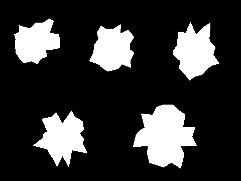
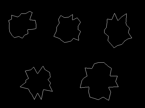
The following example shows a generated binary input image with five non-overlapping ROIs and the corresponding output results. Each ROI is no larger than 128x128 and contains one randomly generated polygon.
|
|
Figure 1: Sample input image (left) and output results (right).
Input and Output Tensors#
The ContourTracing operator takes the following tensors:
Input tensor: A U8 binary image in
HWClayout with{imageHeight, imageWidth, 1}shape. Foreground pixels are nonzero and background pixels are zero.Rect tensor: A 4S32 tensor in
Wlayout with{maxRects}shape. Each element is anNVCVRectI {x, y, width, height}ROI that encloses one foreground component.Output tensor: A U16 tensor in
HWClayout with shape{maxRects, maxContourPixels, 2}. Channel 0 stores the globalxcoordinates and channel 1 stores the globalycoordinates.Length tensor: A U16 tensor in
Wlayout with{maxRects}shape.lenTensor[r]is the number of valid coordinate pairs inoutTensor[r].
Each ROI width must be no greater than MAX_RECT_WIDTH (128) and each ROI height must be no greater than MAX_RECT_HEIGHT (128). The VMEM buffers are allocated using MAX_RECT_AREA (16384) as the size.
Algorithm Description#
The contour tracing algorithm uses an 8-connectivity traversal similar to Moore-neighbor tracing. It first finds a start pixel on the contour, then walks the boundary clockwise by searching the current pixel’s 3x3 neighborhood for the next contour pixel. The traversal continues until it returns to the original start pixel.
Bitmap#
For each pixel, the ContourTracing operator uses its 8-neighbor bitmap to decide whether it is a boundary pixel. The bitmap is an 8-bit value that records the foreground/background state of the eight surrounding pixels in the 3x3 neighborhood. Each bit is set when the corresponding neighbor is foreground.
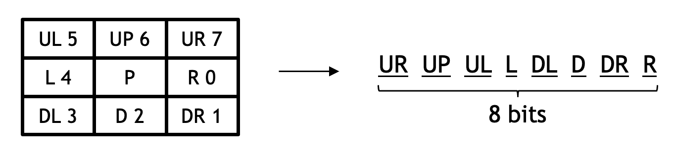
Figure 2: 8-neighbor bitmap#
The bitmap uses this direction encoding: R = 0, DR = 1, D = 2, DL = 3, L = 4, UL = 5, U = 6, and UR = 7.
A pixel is a boundary pixel when the input pixel itself is foreground and at least one of its 4-connected neighbors is background:
input && ((bitmap & 0x55) != 0x55)
The two cases below illustrate why the boundary test uses the 4-connected neighbor mask 0x55. In Case 1, the diagonal background pixel does not make P a boundary pixel because the contour goes from A directly to B. In Case 2, the top neighbor of P is background, so P is on the boundary and the contour goes from A to P to C.
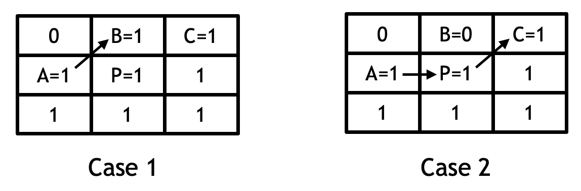
Figure 3: Why the boundary test uses the 4-connected neighbor mask#
NextDir & PrevDir#
The contour is traversed as an 8-connected foreground boundary. nextDir is the direction from the current contour pixel to the next contour pixel. prevDir is the direction of the move from the adjacent background pixel to the next contour pixel. In Figure 4, the current contour pixel is P, and the next contour pixel is Q. Because Q is to the right of P, the nextDir of P is R. Because the background pixel used to enter Q is above Q, the prevDir of Q is D.
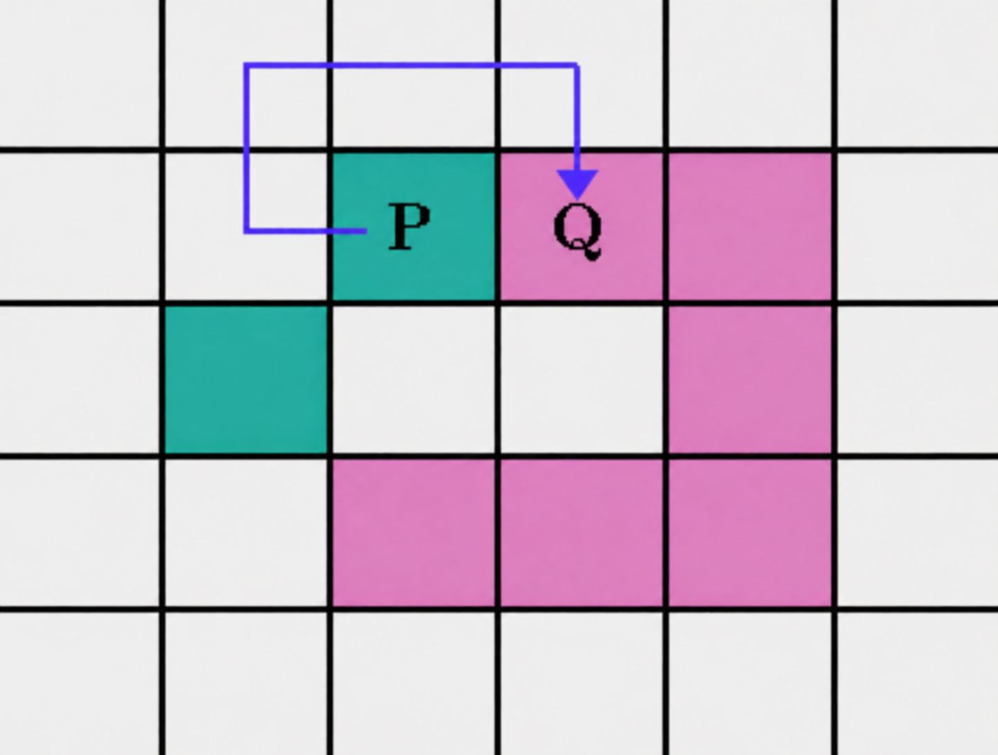
Figure 4: nextDir and prevDir.#
Because the previous background pixel is 4-connected to the next contour pixel, the valid prevDir values are only 0, 2, 4, 6. After taking a foreground step nextDir, the next prevDir is:
prevDir = (nextDir + 2) & 0x6;
With this definition, prevDir has only four possible values, which keeps the direction lookup table compact. It also reduces the number of VPU intrinsics required in the device code.
Direction Lookup Table#
Before tracing starts, the host prepares a direction lookup table for all possible 8-neighbor bitmap values. Each entry is a 16-bit value where every 4 bits represent the nextDir for one prevDir value:
Bit range |
Meaning |
|---|---|
|
|
|
|
|
|
|
|
During traversal, the device uses the current pixel’s bitmap to load the corresponding table entry. Then it uses prevDir to extract nextDir from that entry.
nextDir = (entry >> (2 * prevDir)) & 0xF;
After nextDir is found, it is used to update the coordinates.
To build the direction table, for each bitmap and prevDir pair, the table builder follows prevDir backward to a background pixel, then searches clockwise from that background pixel. The first foreground neighbor found in this search is the next contour pixel.
Implementation Details#
For each ROI, the device code performs contour tracing in three steps:
Generate the 8-neighbor bitmap for every pixel in the ROI.
Find four start pixels from the horizontal and vertical midlines.
Trace four contour segments in parallel and merge them into the final output order.
Bitmap Generation#
Bitmap generation is implemented with the existing 3x3 Conv2d primitive. The device code generates the bitmap in three steps:
Split the input ROI into even-row and odd-row buffers, with zero padding around them. This is required by the Conv2d primitive.
Run the Conv2d primitive with a hardcoded 3x3 bitmap kernel.
Repack the Conv2d result when the ROI width is greater than 64. This is because Conv2d requires the output linepitch to be 128 when the width is between 64 and 128. See the Conv2d code and documentation for details.

Figure 5: Bitmap generation with the Conv2d primitive.#
Start Pixel Search#
To find four start pixels, the device code scans:
The horizontal midline to find the left and right contour intersections;
The vertical midline to find the top and bottom contour intersections.
The horizontal scan is vectorized because the memory access is contiguous. The vertical scan is scalar because the access pattern is strided by the ROI width. The four start pixels define four contour segments that will be traced in parallel:
Segment |
Traversal |
|---|---|
0 |
Left start pixel to top start pixel |
1 |
Top start pixel to right start pixel |
2 |
Right start pixel to bottom start pixel |
3 |
Bottom start pixel to left start pixel |
4-Way Table Reformatting#
The trace loop uses vlookup_4hbu to load four bitmap values and vlookup_4hu to load four direction-table entries. These lookup intrinsics expect a 4-way table layout. The device code therefore reformats both the bitmap buffer and the direction table into a four-subtable layout before tracing.
4-Way Contour Traversal#
The trace kernel runs four contour segments in parallel. Each vector lane is responsible for one segment, starting from one start pixel and stopping when it reaches its target pixel.
The hot loop performs:
Store the current contour pixel to the corresponding segment buffer.
Look up the current pixel bitmap and the corresponding direction-table entry.
Extract
nextDirfrom the entry, then use it to update the coordinates.Check whether each lane has reached its segment endpoint.
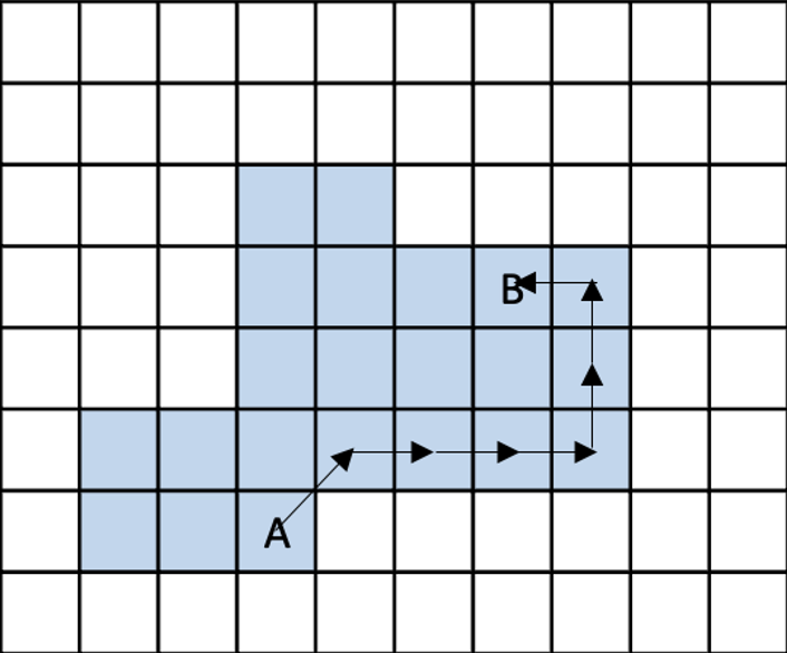
Figure 6: Segment traversal from A to B.#
The loop also counts the length of each segment. After the loop completes, the segment lengths are written to a VMEM buffer for the following merge step.
Segment Storage and Merge#
The four lanes write to four different memory locations:
Segment 0 writes to the first half of
outBufin superbank C.Segment 1 writes to the second half of
outBufin superbank C.Segments 2 and 3 write to two dedicated scratch buffers in superbank B.
After tracing completes, segment 0 is already at the beginning of the output buffer. The device code then copies segment 1, segment 2, and segment 3 after segment 0 in order, skipping any empty segment. Each segment includes its start pixel but not its end pixel, so adjacent segments do not repeat shared endpoints. This produces one continuous contour sequence in outBuf.
Dataflow and Buffering#
The operator uses:
RasterDataFlow for the rectangle (ROI) tensor;
SequenceDataFlow for input ROI transfers;
SequenceDataFlow for output contour sequence transfers;
RasterDataFlow for the contour length tensor.
Input and output VMEM buffers are ping-ponged across ROIs. While the VPU processes the current ROI, the next input ROI can be transferred into the alternate input buffer, and a previously completed output contour sequence can be transferred back to DRAM.
Constraints#
The current implementation has the following constraints:
The operator only supports U8 for input tensors.
The operator only supports U16 for output tensors.
The output tensor must have two channels for
xandycoordinates.The maximum number of ROIs per input tensor is 32.
The width and height of each ROI must be no greater than 128.
Each ROI should contain one closed filled foreground component.
Performance#
The performance of the ContourTracing operator is data dependent. The number of trace-loop iterations depends on the contour length and on how evenly the start pixels split the contour. If one segment is much longer than the others, the other vector lanes finish early, which reduces parallel efficiency.
We evaluated 2-way, 4-way, and 8-way designs, where N-way means using N start pixels to split the contour into N segments. The 4-way design performed best and clearly improved over 2-way. The 8-way design shortened the trace loop further, but its extra overhead removed the benefit. Therefore the current implementation uses 4-way tracing.
The tables below use a 1000x1000 U8 image. Polygon ROIs contain the random polygons shown in the Overview. Comb ROIs contain 2-pixel bars across a central spine, a long contour that splits evenly into the four segments. Unbalanced ROIs contain a block with slots cut into its upper left, so that one segment holds almost the whole contour. Contour Length is the mean number of contour pixels per ROI.
Execution Time is the average time required to execute the operator on a single VPU core.
Note that each PVA contains two VPU cores, which can operate in parallel to process two streams simultaneously, or reduce execution time by approximately half by splitting the workload between the two cores.
Total Power represents the average total power consumed by the module when the operator is executed concurrently on both VPU cores.
Idle power is approximately 7.6 W on Jetson AGX Orin and 11.8 W on Jetson AGX Thor when the PVA is not processing data.
For detailed information on interpreting the performance table below and understanding the benchmarking setup, see Performance Benchmark.
ROIs |
ROI Size |
Shape |
Contour Length |
Execution Time |
Submit Latency |
Total Power |
|---|---|---|---|---|---|---|
1 |
128x128 |
Polygon |
411 |
0.039ms |
0.004ms |
9.109W |
8 |
128x128 |
Polygon |
423 |
0.110ms |
0.004ms |
9.71W |
32 |
128x128 |
Polygon |
422 |
0.352ms |
0.004ms |
9.81W |
32 |
64x64 |
Polygon |
208 |
0.167ms |
0.004ms |
9.71W |
32 |
32x32 |
Polygon |
102 |
0.104ms |
0.004ms |
9.21W |
32 |
128x128 |
Comb (long contour) |
7940 |
2.222ms |
0.006ms |
9.408W |
32 |
128x128 |
Unbalanced (one long segment) |
3470 |
3.181ms |
0.005ms |
9.207W |
ROIs |
ROI Size |
Shape |
Contour Length |
Execution Time |
Submit Latency |
Total Power |
|---|---|---|---|---|---|---|
1 |
128x128 |
Polygon |
411 |
0.038ms |
0.003ms |
12.862W |
8 |
128x128 |
Polygon |
423 |
0.118ms |
0.003ms |
13.155W |
32 |
128x128 |
Polygon |
422 |
0.392ms |
0.003ms |
13.155W |
32 |
64x64 |
Polygon |
208 |
0.184ms |
0.003ms |
12.761W |
32 |
32x32 |
Polygon |
102 |
0.112ms |
0.003ms |
13.155W |
32 |
128x128 |
Comb (long contour) |
7940 |
2.497ms |
0.005ms |
12.55W |
32 |
128x128 |
Unbalanced (one long segment) |
3470 |
3.579ms |
0.003ms |
12.449W |