

RadarCoherentIntegration#
Overview#
Radar coherent integration [1] forms a range-Doppler detection map by combining complex samples across Rx channels for every steering direction. For each range-Doppler cell, the operator retains the largest beam magnitude and then non-coherently accumulates those magnitudes across stride-separated Doppler folds. This improves sensitivity while supporting arbitrary planar Rx antenna locations and two range-Doppler input layouts.
Algorithm Description#
For complex range-Doppler input X[r,k,d] and complex Q15 steering vectors
S[a,e,k], the operator evaluates every azimuth and elevation beam:
Here, r, d, k, a, and e index Range, Doppler, Rx,
azimuth, and elevation, respectively.
The final map accumulates stride-separated Doppler bins:
where \(N_d\) is the number of Doppler bins, \(N_f\) is
repeatFold, and \(W\) is the folded width. The Rx reduction preserves
phase and is coherent; the fold reduction operates on magnitudes and is
non-coherent.
After configured output scaling and U32 encoding, the maps corresponding to
\(C\) and \(F\) are written to coherentIntegrationRx and
coherentIntegrationFinal, respectively.
Applications can provide calibrated steering vectors or use
pvaCoherentIntegrationComputeSteeringVectors() as documented in the
RadarCoherentIntegration API.
Implementation Details#
Range and Doppler Tiling#
The kernel processes the range-Doppler map in tiles. A tile covers R
consecutive Range rows, one Doppler fold of
W = numDopplerBins / repeatFold bins, and all Rx channels. The kernel
processes all folds of one Range tile before moving to the next Range tile,
so the fold accumulator remains in VMEM.
A cell contains all Rx samples at one (Range, Doppler) position, and a tile
contains R * W cells. The host selects R as follows:
Compute the smaller of the raw-input capacity (\(64\,\text{KiB} / (8\,\text{B} \times \text{numRx})\)) and the capacity of each S16 high- or residual-limb buffer (\(48\,\text{KiB} / (4\,\text{B} \times \text{numRx})\)), rounded down to a multiple of 16 cells.
Divide the cell capacity by
Wto obtain the Range-row limit.Select the largest divisor of
numRangeBinsthat does not exceed the row limit, so every tile is full.
For example, with 8 Rx, 512 Doppler bins, and repeatFold = 4, W is
128 and the capacity is min(1024, 1536) = 1024 cells. Therefore,
R <= 8. With 256 Range bins, R = 8, giving 32 Range tiles with four
folds each.
If numRangeBins has no divisor near the row limit, R can become 1.
For example, 257 is prime and therefore uses one Range row per tile, reducing
throughput. When possible, use a Range count with a large divisor at or below
the row limit.
Dataflow Configuration#
The host configures four sequence dataflows:
A raw-input flow transfers one complete fold for all Rx channels.
A steering flow transfers the complete packed steering grid once into the 48 KiB steering buffer and keeps it resident for the submission.
A ping-pong output flow writes the unfolded Rx-coherent map.
A separate output flow writes the folded map after the last fold.
The next raw tile is transferred while the VPU searches the current tile. Unfolded output DMA is also overlapped with beam search, peak-to-magnitude conversion and encoding, and fold accumulation.
VPU Workflow#
For each Range tile and Doppler fold, the VPU performs these stages:
Preprocessing: Round each complex S32 component by one bit to \(x'\), then choose a per-cell split shift \(s\) shared by all Rx components. Store two exact S16 parts, called the high (\(h\)) and residual (\(r\)) limbs, such that \(x' = h 2^s + r\).
Beam search: For every steering beam, form complex dot products \(H\) and \(R\) from the high and residual limbs and combine them as \(H + R/2^s\), with the kernel’s Rx-dependent fixed-point rounding. Compute the combined dot product’s 48-bit power and retain the maximum for each cell.
Magnitude and encoding: Rebuild the stored 48-bit peak power from its low and high words, convert it to FP32, take its correctly rounded square root, multiply by \(2^{s+t-7}\) to restore the scale, where \(t = \lceil\log_2(\mathrm{numRx})\rceil\) is
termShift, and encode the unfolded U32 magnitude.Fold accumulation: Accumulate FP32 magnitudes across Doppler folds.
Final encoding: Encode the final folded U32 map after the last fold.
The device-side processing flow is shown in Figure 1.
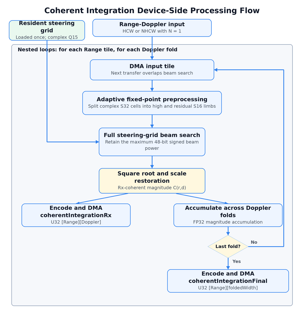
Figure 1: Coherent integration device-side processing flow.#
For Rx4 and Rx8, each pass over the tile evaluates two beams. For Rx12 and Rx16, each pass evaluates one beam to stay within the VPU register-file capacity. If the number of beams is odd, the final pass evaluates one beam.
Device Specialization and Memory#
The operator has four VPU executables, one for each Rx count. Operator creation selects one, so the Rx count is a compile-time constant in the preprocessing and search loops.
The high and residual limbs are in different VMEM superbanks (B and C), so the beam search loads both in the same cycle.
Performance#
The exhaustive beam search is compute-bound and dominates latency for nontrivial steering grids. Latency scales primarily with the number of range-Doppler cells, steering beams, and Rx channels. Input and output DMA are overlapped with computation.
Execution Time is the average time required to execute the operator on a single VPU core.
Note that each PVA contains two VPU cores, which can operate in parallel to process two streams simultaneously, or reduce execution time by approximately half by splitting the workload between the two cores.
Total Power represents the average total power consumed by the module when the operator is executed concurrently on both VPU cores.
Idle power is approximately 7.6 W on Jetson AGX Orin and 11.8 W on Jetson AGX Thor when the PVA is not processing data.
For detailed information on interpreting the performance table below and understanding the benchmarking setup, see Performance Benchmark.
Range Bins |
Doppler Bins |
Rx Antennas |
Doppler Folds |
Azimuth Bins |
Elevation Bins |
Input Layout |
Execution Time |
Submit Latency |
Total Power |
|---|---|---|---|---|---|---|---|---|---|
32 |
128 |
4 |
4 |
8 |
1 |
RangeRxDoppler |
0.095ms |
0.004ms |
10.508W |
32 |
128 |
8 |
4 |
8 |
1 |
RangeRxDoppler |
0.123ms |
0.004ms |
10.608W |
32 |
128 |
8 |
4 |
8 |
1 |
RangeDopplerRx |
0.161ms |
0.004ms |
12.613W |
32 |
128 |
12 |
4 |
8 |
1 |
RangeDopplerRx |
0.232ms |
0.004ms |
12.613W |
32 |
256 |
12 |
8 |
8 |
1 |
RangeRxDoppler |
0.392ms |
0.004ms |
10.608W |
32 |
256 |
16 |
8 |
8 |
1 |
RangeRxDoppler |
0.480ms |
0.004ms |
10.608W |
32 |
512 |
4 |
16 |
8 |
1 |
RangeDopplerRx |
0.477ms |
0.004ms |
11.312W |
32 |
512 |
16 |
16 |
8 |
1 |
RangeDopplerRx |
0.983ms |
0.004ms |
14.124W |
Range Bins |
Doppler Bins |
Rx Antennas |
Doppler Folds |
Azimuth Bins |
Elevation Bins |
Input Layout |
Execution Time |
Submit Latency |
Total Power |
|---|---|---|---|---|---|---|---|---|---|
32 |
128 |
4 |
4 |
8 |
1 |
RangeRxDoppler |
0.099ms |
0.003ms |
13.155W |
32 |
128 |
8 |
4 |
8 |
1 |
RangeRxDoppler |
0.121ms |
0.003ms |
13.155W |
32 |
128 |
8 |
4 |
8 |
1 |
RangeDopplerRx |
0.152ms |
0.003ms |
14.248W |
32 |
128 |
12 |
4 |
8 |
1 |
RangeDopplerRx |
0.251ms |
0.002ms |
15.147W |
32 |
256 |
12 |
8 |
8 |
1 |
RangeRxDoppler |
0.433ms |
0.003ms |
13.155W |
32 |
256 |
16 |
8 |
8 |
1 |
RangeRxDoppler |
0.532ms |
0.003ms |
13.054W |
32 |
512 |
4 |
16 |
8 |
1 |
RangeDopplerRx |
0.366ms |
0.003ms |
14.662W |
32 |
512 |
16 |
16 |
8 |
1 |
RangeDopplerRx |
1.103ms |
0.003ms |
13.843W |
Reference#
M. A. Richards, Fundamentals of Radar Signal Processing, 2nd Edition, McGraw-Hill, New York, 2014.