

RadarRangeFFT#
Overview#
Range FFT (Fast Fourier Transform) is a fundamental signal processing step in modern radar systems. It transforms time-domain ADC samples collected from each radar pulse (or chirp) into the frequency domain, enabling the extraction of target range (distance) information. By performing a 1D FFT along the fast time (sample) dimension for each antenna channel and chirp, the module converts raw sampled data into a range profile, where each frequency bin corresponds to a specific distance. The output of Range FFT is used as input for subsequent steps such as Doppler FFT (velocity estimation), CFAR detection, and angle estimation.
Windowing is crucial for minimizing spectral leakage in FFT processing. This module supports multiple window types (e.g., Hanning, Hamming) with different coefficients defined. Users can select or set the window function according to their application needs.
Input (beat signal of one chirp) |
Output (range profile) |
|---|---|
|
|
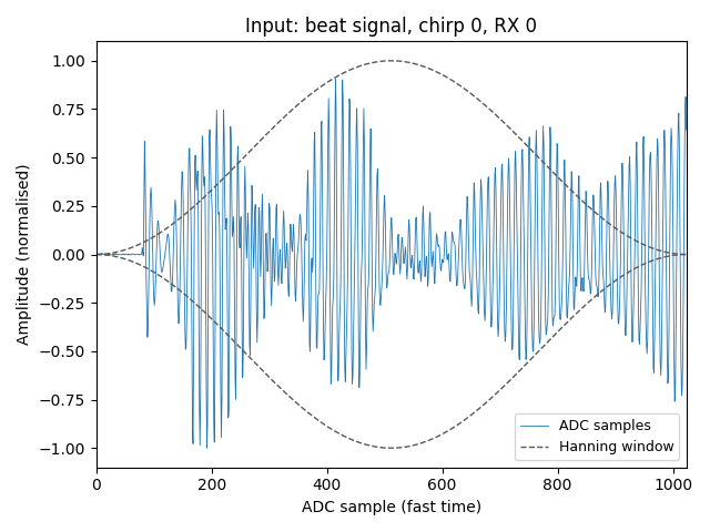
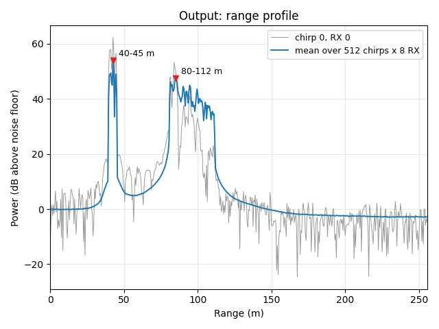
One frame of the 8T8R recording (pipelines/assets/radar/8t8r/radar_raw_8t8r_1.bin): 512 chirps × 8 RX × 1024 samples, Hanning window, 512 range bins of 0.5 m. Each reflector is a beat tone whose frequency grows with range; the FFT turns it into a peak.
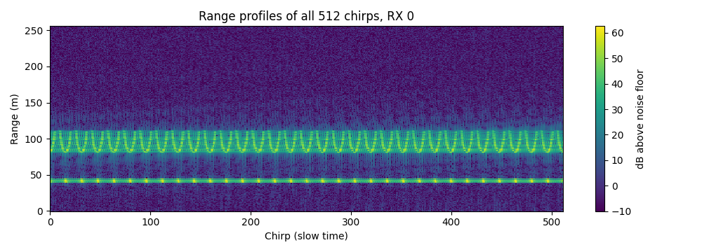
Range profiles of all 512 chirps (RX 0): the reflectors stay at constant range; the ripple along the chirps comes from the transmitters’ DDM phase codes.#
Algorithm Description#
The Range FFT operator performs a 1D FFT along the fast time (sample) dimension for each antenna channel and chirp. The input is a 3D tensor of chirps, channels and samples, arranged as selected by inputLayout.
The operator supports both real-valued int32 input and complex-valued complex int32 input. For real input, the operator emits up to \(N/2+1\) complex range bins from \(N\) real samples. For complex input, the operator emits up to \(N\) complex range bins from \(N\) complex samples.
The output is a 3D tensor of chirps, channels and range bins, arranged as selected by outputLayout.
The operator also accepts and produces an Rx-major arrangement of the same data, selected independently for the input and the output through the
inputLayout and outputLayout fields of PVARangeFFTParams:
PVA_FFT_LAYOUT_DOPPLER_RX_RANGE(the default): the tensor is (chirps x channels x samples/range bins), i.e. the chirp index is the outermost dimension.PVA_FFT_LAYOUT_RX_DOPPLER_RANGE: the tensor is (channels x chirps x samples/range bins), i.e. the Rx channel index is the outermost dimension. This is the arrangement the Rx-major stages of the pipeline consume, and it avoids a separate transpose pass.PVA_FFT_LAYOUT_RANGE_RX_DOPPLER(output only, real input only): the tensor is (range bins x channels x chirps), i.e. the chirps are innermost, which hands the Doppler FFT its chirps contiguously.
The two ends are independent: an Rx-major input may produce a chirp-major output and vice versa. Whichever layout is chosen, the number of Rx channels and the number of chirps must agree between the input and the output; only the dimension that carries each of them changes. In order to achieve the best performance, the implementation uses mixed radix-2, radix-3, radix-4, and radix-5 FFT algorithms. The supported number of samples must be in the range [4, 1024] and even for real input, and [2, 512] for complex input, and also must be factorizable into only factors of 2, 3, 4, and 5 for both real and complex input. For real input, the number of samples must additionally be even, since pairs of real samples are packed into an \(N/2\)-point complex FFT; the complex-input path factorizes \(N\) directly and therefore also supports odd sizes composed of factors 3 and 5.
Implementation Details#
Parameters#
Input tensor with shape (chirps x channels x samples), or (channels x chirps x samples) when
inputLayoutisPVA_FFT_LAYOUT_RX_DOPPLER_RANGE, and data typeint32for real input orcomplex int32for complex input. Real raw ADC input needs to be left-shifted by (32 - raw data bits) bits before the Range FFT operator as the fraction bits during the FFT processing. Complex input uses interleaved real and imaginaryint32components.Window tensor with shape (samples) and data type
int32. The number of window coefficients must match the number of input samples.Output tensor with shape (chirps x channels x range bins), (channels x chirps x range bins) when
outputLayoutisPVA_FFT_LAYOUT_RX_DOPPLER_RANGE, or (range bins x channels x chirps) when it isPVA_FFT_LAYOUT_RANGE_RX_DOPPLER, and data typecomplex int32.For real input, the number of output range bins cannot be greater than \(N/2+1\). For complex input, the number of output range bins cannot be greater than \(N\).
inputLayoutmust bePVA_FFT_LAYOUT_DOPPLER_RX_RANGEorPVA_FFT_LAYOUT_RX_DOPPLER_RANGE;outputLayoutmay additionally bePVA_FFT_LAYOUT_RANGE_RX_DOPPLER. Any other layout is rejected.When either end uses
PVA_FFT_LAYOUT_RX_DOPPLER_RANGE, or the output usesPVA_FFT_LAYOUT_RANGE_RX_DOPPLER, the number of chirps must be a multiple of 8.G (1 to 8), the wide-tile packing factor described under Dataflow Configuration, follows from the arguments: it is the largest value, up to the maximum for the number of samples below, for which the number of chirps is a multiple of 8 x G and, for a
PVA_FFT_LAYOUT_RX_DOPPLER_RANGEoutput with (channels x chirps) above 2048 x G, the conditions listed for that output hold. The maximum among the supported sizes is:real input: 8 for 4 to 108 samples, 7 for 120 to 144, 6 for 150 to 160, 5 for 162 (6 with
PVA_FFT_LAYOUT_RANGE_RX_DOPPLERoutput), 5 for 180 to 192, 4 for 200 to 240, 3 for 250 to 324, 2 for 360 to 486, and 1 for 500 to 1024;complex input: 8 for 2 to 54 samples, 7 for 60 to 72, 6 for 75 to 81, 5 for 90 to 96, 4 for 100 to 120, 3 for 125 to 162, 2 for 180 to 243, and 1 for 250 to 512.
When either end uses
PVA_FFT_LAYOUT_DOPPLER_RX_RANGE, there can be at most 256 channels and the number of chirps cannot exceed 2048 x G.When
inputLayoutisPVA_FFT_LAYOUT_DOPPLER_RX_RANGE, (channels x samples) cannot exceed 65535 for real input and 32767 for complex input; whenoutputLayoutis, (channels x range bins) cannot exceed 32767.When
outputLayoutisPVA_FFT_LAYOUT_RANGE_RX_DOPPLER: the input must be real, and (channels x chirps) cannot exceed 2048 x G.The input, window and output tensors must be densely packed, with no padding between dimensions.
When
inputLayoutisPVA_FFT_LAYOUT_RX_DOPPLER_RANGEthe product (channels x chirps) cannot exceed 2048.When
outputLayoutisPVA_FFT_LAYOUT_RX_DOPPLER_RANGEand (channels x chirps) exceeds 2048 x G:the number of range bins must be the maximum: \(N/2+1\) for real input, \(N\) for complex input;
for real input, \(N\) must be a multiple of 16; for complex input, \(N\) must be one more than a multiple of 8, which among the supported complex sizes leaves only 9, 25, 81 and 225;
(channels x chirps / (8 x G)) must be the product of an even number and another number, both no greater than 256, with the even number times (64 x G x range bins) no greater than 8388607.
Dataflow Configuration#
Use 1 SQDF (SequenceDataflow) to transfer the twiddle factors and the coefficients of the window function from DRAM to VMEM.
Use 1 input and 1 output RDFs (RasterDataflow) to split the whole input/output tensor into tiles and transfer them between DRAM and VMEM one by one.
Wide-tile packing: a tile carries G blocks of 8 chirps (G up to 8) and the G blocks run as one fused FFT, which divides the tile count by G and lengthens every kernel’s inner loop. The operator picks the largest G for which the number of chirps is a multiple of 8 x G, the FFT has at most five stages (its digit reverse needs a free agen dimension for the group stride), an Rx-major output of more than 256 tiles can still be split for its SQDF, and the packed input tile, output tile and FFT intermediates each fit their VMEM buffer; otherwise G is 1.
The width of the input tile equals to the number of samples (for complex input, twice the number of complex samples, as the real and imaginary components are interleaved) and the height equals to 8 x G chirps.
The width of the output tile equals to the number of range bins (interleaved complex components) and the height equals to 8 x G chirps. For
PVA_FFT_LAYOUT_RANGE_RX_DOPPLERthe output tile is the transpose: 8 x G chirps wide by every range bin tall.The tile shape is the same for the range-innermost layouts; only the shape of the surface the tiles walk over changes. A chirp-major tensor is a short, wide image of (chirps) rows by (channels x samples) columns, whereas an Rx-major tensor is a tall, narrow image of (channels x chirps) rows by (samples) columns. Both are scanned in column-major order.
An Rx-major output of more than 256 tiles of 8 x G chirps is written through a SQDF instead of an RDF, since 256 is the per-dimension tile limit of an RDF. This path is subject to the constraints listed under Parameters.
For
PVA_FFT_LAYOUT_RANGE_RX_DOPPLERthe output RDF row is one range bin of (channels x chirps) complex values, so its line pitch has no range-bin term and the layout is not limited by the range bin count.
VMEM Buffer Allocation#
1 buffer with data type
int32to store the twiddle factors and 1 buffer with data typeint32to store the coefficients of the window function.1 input with data type
int32and double buffering to store the data of each tile reading from the input tensor. Complex input stores interleaved real and imaginary components.1 output with data type
int32and double buffering to store the data of each tile writing to the output tensor.2 temporary buffers with data type
int32to store the intermediate data of the FFT stages and the transpose operation. The real-input path uses the second temporary buffer during the post-processing stage to avoid overwriting the input buffer while it performs the in-place symmetry update. The complex-input path only uses one of the temporary buffers.
Workflow Implementation#
For real-valued input, the Range FFT leverages FFT symmetry to reduce the computation by converting the real FFT of size \(N\) into a complex FFT of size \(N/2\). For complex-valued input, the operator runs the full complex FFT of size \(N\) directly and produces the full complex spectrum.
The kernels of the Range FFT operator are implemented with high performance fixed-point vectorized instructions on PVA with the following steps:
The windowing function to apply the window coefficients and transpose the input data to follow the batch FFT data layout requirements. The real-input path packs real samples into complex-valued data; the complex-input path preserves the interleaved real and imaginary components.
FFT stages over \(N/2\) complex points for real input or \(N\) complex points for complex input, using the mixed-radix stage functions (fft_batched_radix4, fft_batched_radix3, and fft_batched_radix5, plus a radix-2 stage) selected according to the factorization of the FFT size.
The final radix stage performs the digit-reversal addressing combined with the transpose using the fft_batched_radix{2,3,4,5}_digit_reverse_transpose functions. The radix used for the digit reversal matches the trailing factor of the FFT size: radix-4 (or radix-2 when the number of power-of-two stages is odd) for power-of-two sizes, and radix-3 or radix-5 for the corresponding mixed-radix sizes.
For real input, the fft_real_batched_post_process_transpose function generates the \((N/2+1)\) complex-valued output data and transposes the output data layout to follow the batch FFT data layout requirements for the next Doppler FFT. For
PVA_FFT_LAYOUT_RANGE_RX_DOPPLERthe same store writes each vector contiguously (lane offset 0), one row per range bin, because the chirps are already innermost. For complex input, this post-processing stage is skipped and the full-spectrum complex bins produced by the digit-reverse-transpose stage are written directly.
Agen Configuration#
The agen configurations are set according to the radix-4/radix-2 operation in each stage. The agen configurations in the last radix stage are set to implement the digit reversal addressing with zero overhead. With wide-tile packing, each agen also carries a group dimension of G that steps between the 8-chirp blocks of a tile (a stride of 0 for the twiddle and window tables, which every block reuses), so each stage function runs once per tile over all G blocks. The digit reverse puts the group dimension in the first agen dimension its stages leave free. One problem is that the overflow may happen during the accumulation of the butterfly calculation in the radix-4/radix-2 operation. The solution is to set the rounding parameter of the store agen in each stage to 2-bit for radix-4 and 1-bit for radix-2. The rounding parameter should also account for the quantization bits (qbits) of the twiddle factors when they are used in the current stage. When storing the output data at the end of each stage, the rounding operation prevents accumulation overflow in subsequent stages.
VPU Function Implementation#
To pack the real-valued input data into complex-valued data with zero overhead, we use the dvint_load_transp2_di to load the corresponding location of the data in the windowing function. For complex input, the same workflow operates on interleaved real and imaginary components and skips the real-FFT post-processing stage.
The fft_batched_radix4 function uses the following instructions to implement the radix-4 operation:
vaddsub4x2_0andvaddsub4x2_1are used to accelerate the butterfly calculation in the radix-4 operation.dvcmulw_t16is used to accelerate the complex multiplication with the twiddle factors.
To achieve the best performance, we manually allocate the vector registers and unroll the loop body in the fft_batched_radix4 function.
The fft_batched_radix3 and fft_batched_radix5 functions use the following instructions to implement the radix-3 and radix-5 operation:
dvadd3is used to accelerate the butterfly calculation in the radix-3 and radix-5 operation.dvcmulw_t16is used to accelerate the complex multiplication with the twiddle factors.dvmulw_t16applies fixed-point reciprocal scaling after each butterfly: 1/3 for radix-3 and 1/5 for radix-5. This normalizes the butterfly outputs and limits fixed-point value growth.
Performance#
Execution Time is the average time required to execute the operator on a single VPU core.
Note that each PVA contains two VPU cores, which can operate in parallel to process two streams simultaneously, or reduce execution time by approximately half by splitting the workload between the two cores.
Total Power represents the average total power consumed by the module when the operator is executed concurrently on both VPU cores.
Idle power is approximately 7.6 W on Jetson AGX Orin and 11.8 W on Jetson AGX Thor when the PVA is not processing data.
For detailed information on interpreting the performance table below and understanding the benchmarking setup, see Performance Benchmark.
Samples |
Rx Antennas |
Chirps |
Input Layout |
Output Layout |
Input Type |
Output Type |
Execution Time |
Submit Latency |
Total Power |
|---|---|---|---|---|---|---|---|---|---|
64 |
8 |
256 |
DopplerRxRange |
DopplerRxRange |
S32 |
2S32 |
0.109ms |
0.003ms |
13.91W |
64 |
16 |
256 |
DopplerRxRange |
DopplerRxRange |
S32 |
2S32 |
0.181ms |
0.003ms |
15.12W |
64 |
64 |
256 |
DopplerRxRange |
DopplerRxRange |
S32 |
2S32 |
0.615ms |
0.005ms |
16.22W |
64 |
192 |
256 |
DopplerRxRange |
DopplerRxRange |
S32 |
2S32 |
1.779ms |
0.006ms |
16.821W |
256 |
4 |
256 |
DopplerRxRange |
RangeRxDoppler |
S32 |
2S32 |
0.191ms |
0.003ms |
14.506W |
256 |
192 |
64 |
DopplerRxRange |
DopplerRxRange |
S32 |
2S32 |
1.890ms |
0.006ms |
16.005W |
512 |
1 |
512 |
DopplerRxRange |
DopplerRxRange |
S32 |
2S32 |
0.190ms |
0.003ms |
14.406W |
512 |
4 |
8 |
DopplerRxRange |
DopplerRxRange |
S32 |
2S32 |
0.047ms |
0.003ms |
10.31W |
512 |
4 |
9 |
DopplerRxRange |
DopplerRxRange |
S32 |
2S32 |
0.054ms |
0.003ms |
10.209W |
512 |
4 |
16 |
DopplerRxRange |
DopplerRxRange |
S32 |
2S32 |
0.056ms |
0.003ms |
11.308W |
512 |
4 |
256 |
DopplerRxRange |
DopplerRxRange |
S32 |
2S32 |
0.345ms |
0.004ms |
14.905W |
512 |
4 |
256 |
RxDopplerRange |
RxDopplerRange |
S32 |
2S32 |
0.344ms |
0.004ms |
15.006W |
512 |
4 |
512 |
DopplerRxRange |
DopplerRxRange |
S32 |
2S32 |
0.653ms |
0.006ms |
15.006W |
512 |
8 |
512 |
DopplerRxRange |
DopplerRxRange |
S32 |
2S32 |
1.267ms |
0.006ms |
15.405W |
600 |
4 |
512 |
DopplerRxRange |
DopplerRxRange |
S32 |
2S32 |
2.423ms |
0.006ms |
12.404W |
600 |
8 |
512 |
DopplerRxRange |
DopplerRxRange |
S32 |
2S32 |
4.801ms |
0.006ms |
12.404W |
640 |
4 |
512 |
DopplerRxRange |
DopplerRxRange |
S32 |
2S32 |
1.540ms |
0.006ms |
13.504W |
640 |
8 |
512 |
DopplerRxRange |
DopplerRxRange |
S32 |
2S32 |
3.036ms |
0.006ms |
13.504W |
750 |
4 |
512 |
DopplerRxRange |
DopplerRxRange |
S32 |
2S32 |
3.972ms |
0.007ms |
11.804W |
750 |
8 |
512 |
DopplerRxRange |
DopplerRxRange |
S32 |
2S32 |
7.895ms |
0.007ms |
11.804W |
900 |
4 |
512 |
DopplerRxRange |
DopplerRxRange |
S32 |
2S32 |
4.040ms |
0.007ms |
12.702W |
900 |
8 |
512 |
DopplerRxRange |
DopplerRxRange |
S32 |
2S32 |
8.039ms |
0.007ms |
12.702W |
1024 |
1 |
512 |
DopplerRxRange |
DopplerRxRange |
S32 |
2S32 |
0.343ms |
0.004ms |
15.304W |
1024 |
4 |
512 |
DopplerRxRange |
DopplerRxRange |
S32 |
2S32 |
1.258ms |
0.006ms |
15.804W |
1024 |
8 |
512 |
DopplerRxRange |
DopplerRxRange |
S32 |
2S32 |
2.473ms |
0.006ms |
15.804W |
1024 |
8 |
512 |
DopplerRxRange |
RxDopplerRange |
S32 |
2S32 |
3.400ms |
0.007ms |
13.705W |
Samples |
Rx Antennas |
Chirps |
Input Layout |
Output Layout |
Input Type |
Output Type |
Execution Time |
Submit Latency |
Total Power |
|---|---|---|---|---|---|---|---|---|---|
64 |
8 |
256 |
DopplerRxRange |
DopplerRxRange |
S32 |
2S32 |
0.103ms |
0.002ms |
16.16W |
64 |
16 |
256 |
DopplerRxRange |
DopplerRxRange |
S32 |
2S32 |
0.182ms |
0.003ms |
16.655W |
64 |
64 |
256 |
DopplerRxRange |
DopplerRxRange |
S32 |
2S32 |
0.663ms |
0.003ms |
17.265W |
64 |
192 |
256 |
DopplerRxRange |
DopplerRxRange |
S32 |
2S32 |
1.949ms |
0.004ms |
17.569W |
256 |
4 |
256 |
DopplerRxRange |
RangeRxDoppler |
S32 |
2S32 |
0.195ms |
0.002ms |
15.856W |
256 |
192 |
64 |
DopplerRxRange |
DopplerRxRange |
S32 |
2S32 |
2.105ms |
0.004ms |
16.453W |
512 |
1 |
512 |
DopplerRxRange |
DopplerRxRange |
S32 |
2S32 |
0.194ms |
0.002ms |
15.552W |
512 |
4 |
8 |
DopplerRxRange |
DopplerRxRange |
S32 |
2S32 |
0.033ms |
0.002ms |
13.752W |
512 |
4 |
9 |
DopplerRxRange |
DopplerRxRange |
S32 |
2S32 |
0.042ms |
0.002ms |
13.752W |
512 |
4 |
16 |
DopplerRxRange |
DopplerRxRange |
S32 |
2S32 |
0.044ms |
0.002ms |
14.349W |
512 |
4 |
256 |
DopplerRxRange |
DopplerRxRange |
S32 |
2S32 |
0.368ms |
0.003ms |
15.946W |
512 |
4 |
256 |
RxDopplerRange |
RxDopplerRange |
S32 |
2S32 |
0.367ms |
0.003ms |
16.048W |
512 |
4 |
512 |
DopplerRxRange |
DopplerRxRange |
S32 |
2S32 |
0.713ms |
0.003ms |
16.048W |
512 |
8 |
512 |
DopplerRxRange |
DopplerRxRange |
S32 |
2S32 |
1.404ms |
0.003ms |
16.149W |
600 |
4 |
512 |
DopplerRxRange |
DopplerRxRange |
S32 |
2S32 |
2.701ms |
0.003ms |
13.752W |
600 |
8 |
512 |
DopplerRxRange |
DopplerRxRange |
S32 |
2S32 |
5.380ms |
0.004ms |
14.248W |
640 |
4 |
512 |
DopplerRxRange |
DopplerRxRange |
S32 |
2S32 |
1.707ms |
0.003ms |
15.046W |
640 |
8 |
512 |
DopplerRxRange |
DopplerRxRange |
S32 |
2S32 |
3.391ms |
0.004ms |
14.844W |
750 |
4 |
512 |
DopplerRxRange |
DopplerRxRange |
S32 |
2S32 |
4.444ms |
0.003ms |
13.854W |
750 |
8 |
512 |
DopplerRxRange |
DopplerRxRange |
S32 |
2S32 |
8.865ms |
0.004ms |
13.752W |
900 |
4 |
512 |
DopplerRxRange |
DopplerRxRange |
S32 |
2S32 |
4.524ms |
0.003ms |
14.146W |
900 |
8 |
512 |
DopplerRxRange |
DopplerRxRange |
S32 |
2S32 |
9.025ms |
0.005ms |
14.248W |
1024 |
1 |
512 |
DopplerRxRange |
DopplerRxRange |
S32 |
2S32 |
0.366ms |
0.003ms |
16.949W |
1024 |
4 |
512 |
DopplerRxRange |
DopplerRxRange |
S32 |
2S32 |
1.378ms |
0.004ms |
16.138W |
1024 |
8 |
512 |
DopplerRxRange |
DopplerRxRange |
S32 |
2S32 |
2.733ms |
0.005ms |
16.848W |
1024 |
8 |
512 |
DopplerRxRange |
RxDopplerRange |
S32 |
2S32 |
3.267ms |
0.006ms |
16.138W |
Complex (I/Q interleaved) input:
Samples |
Rx Antennas |
Chirps |
Input Type |
Output Type |
Execution Time |
Submit Latency |
Total Power |
|---|---|---|---|---|---|---|---|
256 |
4 |
512 |
2S32 |
2S32 |
0.489ms |
0.005ms |
16.119W |
256 |
8 |
512 |
2S32 |
2S32 |
0.945ms |
0.005ms |
16.518W |
512 |
1 |
512 |
2S32 |
2S32 |
0.286ms |
0.004ms |
15.909W |
512 |
4 |
256 |
2S32 |
2S32 |
0.540ms |
0.005ms |
16.308W |
512 |
4 |
512 |
2S32 |
2S32 |
1.050ms |
0.006ms |
16.417W |
512 |
8 |
512 |
2S32 |
2S32 |
2.041ms |
0.007ms |
16.816W |
Samples |
Rx Antennas |
Chirps |
Input Type |
Output Type |
Execution Time |
Submit Latency |
Total Power |
|---|---|---|---|---|---|---|---|
256 |
4 |
512 |
2S32 |
2S32 |
0.568ms |
0.003ms |
17.163W |
256 |
8 |
512 |
2S32 |
2S32 |
1.120ms |
0.004ms |
16.645W |
512 |
1 |
512 |
2S32 |
2S32 |
0.300ms |
0.003ms |
15.946W |
512 |
4 |
256 |
2S32 |
2S32 |
0.588ms |
0.003ms |
16.341W |
512 |
4 |
512 |
2S32 |
2S32 |
1.152ms |
0.004ms |
17.647W |
512 |
8 |
512 |
2S32 |
2S32 |
2.285ms |
0.005ms |
17.748W |