Devices Window
The Devices window shows data pertaining to the physical devices in a tabular format.

Devices Window Data
|
Data Type |
Description |
|
Health |
Health of the device reflecting the highest alarm severity. Please refer to the Health States table. |
|
Name |
Name of the device Warning
If UFM Agent is running on a device, the following icon will appear next to the device name: 
|
|
GUID |
System GUID of the device |
|
Type |
Type of the device: switch, node, IB router, and getaway |
|
IP |
IP address of the device |
|
Vendor |
The vendor of the device |
|
Firmware Version |
The firmware version installed on the device |
Health States
|
Icon |
Name |
Description |

|
Normal |
Information/notification displayed during normal operating state or a normal system event. |

|
Critical |
Critical means that the operation of the system or a system component fails. |

|
Minor |
Minor reflects a problem in the fabric with no failure. |

|
Warning |
Warning reflects a low priority problem in the fabric with no failure. A warning is asserted when an event exceeds a predefined threshold. |
A right-click on the device name displays a list of actions that can be performed on it.
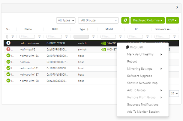
Devices Actions
|
Action |
Description |
|
Firmware Upgrade |
Perform a firmware upgrade on the selected device |
|
Firmware Reset |
Reboot the device. This action is only applicable to unmanaged hosts (servers). |
|
Set Node Description |
Configure a description to this node |
|
Collect System Dump |
Collect the system dump log for a specific device |
|
Add to Group |
Add the selected device to a devices group |
|
Remove from Group |
Remove the selected device from a devices group |
|
Suppress Notifications |
Suppress all event notifications for the device |
|
Add to Monitor Session |
Configure and activate host monitoring |
|
Show in Network Map |
Move to Zoom In tab in network map and add the selected device to filter list |
Collecting system dump for hosts, managed by UFM, is available only for hosts which are set with a valid IPv4 address and installed with MLNX_OFED.
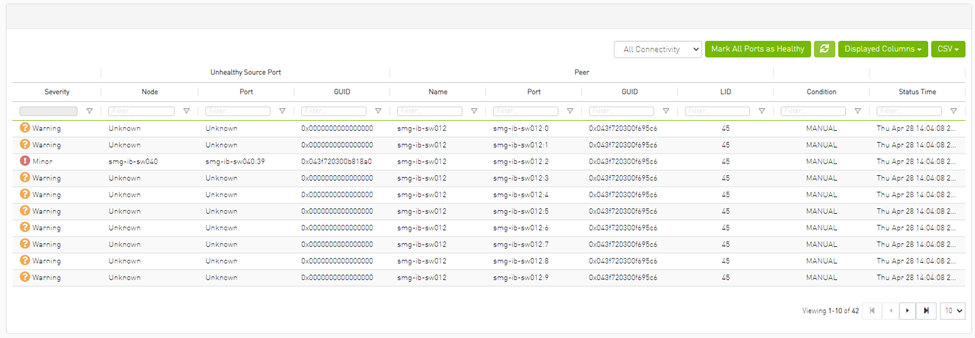
From the Devices table, it is possible to mark devices as healthy or unhealthy using the context menu (right-click).
There are two options for marking a device as unhealthy:
Isolate
No Discover

Server: conf/opensm/opensm-health-policy.conf content:
            0xe41d2d030003e3b0 34 UNHEALTHY isolate
0xe41d2d030003e3b0 19 UNHEALTHY isolate
0xe41d2d030003e3b0 3 UNHEALTHY isolate
0xe41d2d030003e3b0 26 UNHEALTHY isolate
0xe41d2d030003e3b0 0 UNHEALTHY isolate
0xe41d2d030003e3b0 27 UNHEALTHY isolate
0xe41d2d030003e3b0 7 UNHEALTHY isolate
0xe41d2d030003e3b0 10 UNHEALTHY isolate
0xe41d2d030003e3b0 11 UNHEALTHY isolate
0xe41d2d030003e3b0 22 UNHEALTHY isolate
0xe41d2d030003e3b0 18 UNHEALTHY isolate
0xe41d2d030003e3b0 29 UNHEALTHY isolate
0xe41d2d030003e3b0 8 UNHEALTHY isolate
0xe41d2d030003e3b0 5 UNHEALTHY isolate
0xe41d2d030003e3b0 17 UNHEALTHY isolate
0xe41d2d030003e3b0 23 UNHEALTHY isolate
0xe41d2d030003e3b0 15 UNHEALTHY isolate
0xe41d2d030003e3b0 24 UNHEALTHY isolate
0xe41d2d030003e3b0 2 UNHEALTHY isolate
0xe41d2d030003e3b0 16 UNHEALTHY isolate
0xe41d2d030003e3b0 13 UNHEALTHY isolate
0xe41d2d030003e3b0 14 UNHEALTHY isolate
0xe41d2d030003e3b0 32 UNHEALTHY isolate
0xe41d2d030003e3b0 33 UNHEALTHY isolate
0xe41d2d030003e3b0 35 UNHEALTHY isolate
0xe41d2d030003e3b0 20 UNHEALTHY isolate
0xe41d2d030003e3b0 21 UNHEALTHY isolate
0xe41d2d030003e3b0 28 UNHEALTHY isolate
0xe41d2d030003e3b0 1 UNHEALTHY isolate
0xe41d2d030003e3b0 9 UNHEALTHY isolate
0xe41d2d030003e3b0 4 UNHEALTHY isolate
0xe41d2d030003e3b0 31 UNHEALTHY isolate
0xe41d2d030003e3b0 30 UNHEALTHY isolate
0xe41d2d030003e3b0 36 UNHEALTHY isolate
0xe41d2d030003e3b0 12 UNHEALTHY isolate
0xe41d2d030003e3b0 25 UNHEALTHY isolate
0xe41d2d030003e3b0 6 UNHEALTHY isolate
/opt/ufm/files/log/opensm-unhealthy-ports.dump content:


Server /opt/ufm/files/conf/opensm/opensm-health-policy.conf content:
            0xe41d2d030003e3b0 15 HEALTHY
0xe41d2d030003e3b0 25 HEALTHY
0xe41d2d030003e3b0 35 HEALTHY
0xe41d2d030003e3b0 0 HEALTHY
0xe41d2d030003e3b0 11 HEALTHY
0xe41d2d030003e3b0 21 HEALTHY
0xe41d2d030003e3b0 28 HEALTHY
0xe41d2d030003e3b0 7 HEALTHY
0xe41d2d030003e3b0 17 HEALTHY
0xe41d2d030003e3b0 14 HEALTHY
0xe41d2d030003e3b0 24 HEALTHY
0xe41d2d030003e3b0 34 HEALTHY
0xe41d2d030003e3b0 3 HEALTHY
0xe41d2d030003e3b0 10 HEALTHY
0xe41d2d030003e3b0 20 HEALTHY
0xe41d2d030003e3b0 31 HEALTHY
0xe41d2d030003e3b0 6 HEALTHY
0xe41d2d030003e3b0 16 HEALTHY
0xe41d2d030003e3b0 27 HEALTHY
0xe41d2d030003e3b0 2 HEALTHY
0xe41d2d030003e3b0 13 HEALTHY
0xe41d2d030003e3b0 23 HEALTHY
0xe41d2d030003e3b0 33 HEALTHY
0xe41d2d030003e3b0 30 HEALTHY
0xe41d2d030003e3b0 9 HEALTHY
0xe41d2d030003e3b0 19 HEALTHY
0xe41d2d030003e3b0 26 HEALTHY
0xe41d2d030003e3b0 36 HEALTHY
0xe41d2d030003e3b0 5 HEALTHY
0xe41d2d030003e3b0 12 HEALTHY
0xe41d2d030003e3b0 22 HEALTHY
0xe41d2d030003e3b0 32 HEALTHY
0xe41d2d030003e3b0 1 HEALTHY
0xe41d2d030003e3b0 8 HEALTHY
0xe41d2d030003e3b0 18 HEALTHY
0xe41d2d030003e3b0 29 HEALTHY
0xe41d2d030003e3b0 4 HEALTHY
/opt/ufm/files/log/opensm-unhealthy-ports.dump content:
# NodeGUID, PortNum, NodeDesc, PeerNodeGUID, PeerPortNum, PeerNodeDesc, {BadCond1, BadCond2, ...}, timestamp
Software/Firmware Upgrade via FTP
Software and firmware upgrade over FTP is enabled by the UFM Agent. UFM invokes the Software/Firmware Upgrade procedure locally on switches or on hosts. The procedure copies the new software/firmware file from the defined storage location and performs the operation on the device. UFM sends the set of attributes required for performing the software/firmware upgrade to the agent.
The attributes are:
File Transfer Protocol – default FTP
The Software/Firmware upgrade on InfiniScale III ASIC-based switches supports FTP protocol for transmitting files to the local machine.
The Software/Firmware upgrade on InfiniScale IV-based switches and hosts supports TFTP and protocols for transmitting files to the local machine.
IP address of file-storage server
Path to the software/firmware image location
The software/firmware image files should be placed according to the required structure under the defined image storage location. Please refer to section Devices Window.File-storage server access credentials (User/Password)
In-Band Firmware Upgrade
You can perform in-band firmware upgrades for externally managed switches and HCAs. This upgrade procedure does not require the UFM Agent or IP connectivity, but it does require current PSID recognition. Please refer to section PSID and Firmware Version In-Band Discovery. This feature requires that the Mellanox Firmware Toolkit (MFT), which is included in the UFM package, is installed on the UFM server. UFM uses flint from the MFT for in-band firmware burning.
Before upgrading, you must create the firmware repository on the UFM server under the directory /opt/ufm/files/userdata/fw/. The subdirectory should be created for each PSID and one firmware image should be placed under it. For example:
            /opt/ufm/files/userdata/fw/
	 MT_0D80110009
			fw-ConnectX2-rel-2_9_1000-MHQH29B-XTR_A1.bin
	 MT_0F90110002
			fw-IS4-rel-7_4_2040-MIS5023Q_A1-A5.bin
Directory Structure for Software or Firmware Upgrade Over FTP
Before performing a software or firmware upgrade, you must create the following directory structure for the upgrade image. The path to the <ftp user home>/<path>/ directory should be specified in the upgrade dialog box.
            <ftp user home>/<path>/
	 InfiniScale3 - For anafa based switches Software/Firmware upgrade images
			voltaire_fw_images.tar – firmware image file
			ibswmpr-<s/w version>.tar – software image file
	InfiniScale4 - For InfiniScale IV based switches Software/Firmware upgrade images
			firmware_2036_4036.tar – Firmware image file
			upgrade_2036_4036.tgz – Software image file
	OFED /* For host SW upgrade*/
			OFED-<OS label>.tar.bz2
	<PSID>* – For host FW upgrade
			fw_update.img
The <PSID> value is extracted from the mstflint command:
mstflint -d <device> q
The device is extracted from the lspci command. For example:
            # lspci
06:00.0 InfiniBand: Mellanox Technologies MT25208 InfiniHost III Ex
# mstflint -d 06:00.0 q | grep PSID
PSID: VLT0040010001
PSID and Firmware Version In-Band Discovery
The device PSID and device firmware version are required for in-band firmware upgrade and for the correct functioning of Subnet Manager plugins, such as Congestion Control Manager and Lossy Configuration Management. For most devices, UFM discovers this information and displays it in the Device Properties pane. The PSID and the firmware version are discovered by the Vendor-specific MAD.
By default, the gv.cfg file value for event_plugin_option is set to (null). This means that the plugin is disabled and opensm does not send MADs to discover devices' PSID and FW version. Therefore, values for devices' PSID and FW version are taken from ibdiagnet output (section NODES_INFO).
The below is an example of the default value:
event_plugin_options = (null)
To enable the vendor-specific discovery by opemsm, in the gv.cfg configuration file, change the value of event_plugin_option to (--vendinfo –m 1), as shown below:
event_plugin_options = --vendinfo –m 1
If the value is set to –vendinfo –m 1, the data should be supplied by opensm, and in this case the ibdiagnet output is ignored.
In some firmware versions, the information above is currently not available.
Switch Management IP Address Discovery
From NVIDIA switch FM version 27.2010.3942 and up, NVIDIA switches support switch management IP address discovery using MADs. This information can be retrieved as part of ibdiagnet run (ibdiagnet output), and assigned to discover switches in UFM.
There is an option to choose the IP address of which IP protocol version that is assigned to the switch: IPv4 or IPv6.
The discovered_switch_ip_protocol key, located in the gv.cfg file in section [FabricAnalysys], is set to 4 by default. This means that the IP address of type IPv4 is assigned to the switch as its management IP address. In case this value is set to 6, the IP address of type IPv6 is assigned to the switch as its management IP address.
After changing the discover_switch_ip_protocol value in gv.cfg, the UFM Main Model needs to be restarted for the update to take effect. The discovered IP addresses for switches are not persistent in UFM – every UFM Main Model restarts the values of management IP address which is assigned from the ibdiagnet output.
Upgrading Server Software
The ability to update the server software is applicable only for hosts (servers) with the UFM Agent.
To upgrade the software:
Select a device.
From the right-click menu, select Software Update.
Enter the parameters listed in the following table.
Parameter
Description
Protocol
Update is performed via FTP protocol
IP
Enter the host IP
Path
Enter the parent directory of the FTP directory structure for the Upgrade image.
The path should not be an absolute path and should not contain the first slash (/) or trailer slash.
User
Name of the host username
Password
Enter the host password
Click Submit to save your changes.
Upgrading Firmware
You can upgrade firmware over FTP for hosts and switches that are running the UFM Agent, or you can perform an in-band upgrade for externally managed switches and HCAs.
Before you begin the upgrade ensure that the new firmware version is in the correct location. For more information, please refer to section In-Band Firmware Upgrade.
To upgrade the firmware:
Select a host or server.
From the right-click menu, select Firmware Upgrade.
Select protocol In Band.
For upgrade over FTP, enter the parameters listed in the following table.
Parameter
Description
IP
Enter device IP
Path
Enter the parent directory of the FTP directory structure for the Upgrade image.
The path should not be an absolute path and should not contain the first slash (/) or trailer slash.
Username
Name of the host username
Password
Enter the host password
Click submit to save your changes.
WarningThe firmware upgrade takes effect only after the host or externally managed switch is restarted.
Upgrade Cables Transceivers Firmware Version
The main purpose of this feature is to add support for burning of multiple cables transceiver types on multiple devices using linkx tool which is part of flint. This needs to be done from both ends of the cable (switch and HCA/switch).
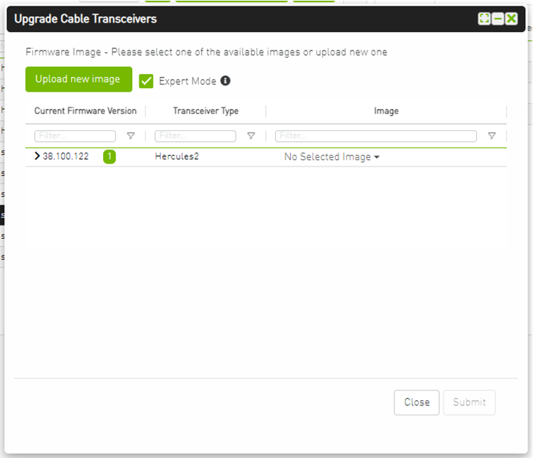
To upgrade cables transceivers FW version:
Navigate to managed elements page
select the target switches and click on Upgrade Cable Transceivers option

A model will be shown containing list of the active firmware versions for the cables of the selected switches, besides the version number, a badge will show the number of matched switches:
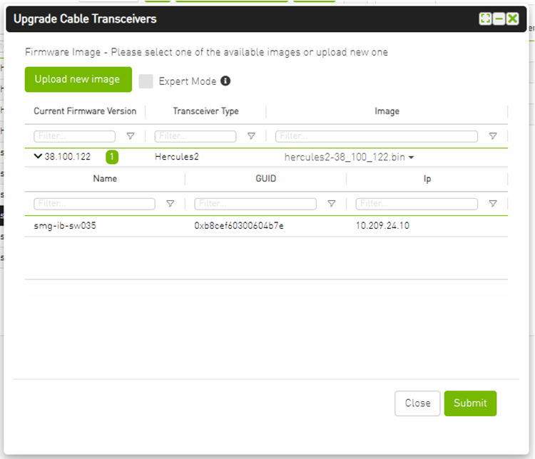
After the user clicks Submit, the GUI will start sending the selected binaries with the relevant switches sequentially, and a model with a progress bar will be shown (this model can be minimized):

After the whole action is completed successfully, you will be able to see the following message at the model bottom The upgrade cable transceivers completed successfully, do you want to activate it? by clicking the yes button it will run a new action on all the burned devices to activate the new uploaded binary image.
Another option to activate burned cables transceivers you can go to the Groups page and right click on the predefined Group named Devices Pending FW Transceivers Reset or you can right click on the upgraded device from managed element page and select Activate cable Transceivers action.

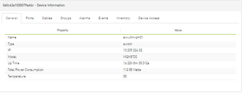
Selecting a device from the Devices table reveals the Device Information table on the right side of the screen. This table provides information on the device’s ports, cables, groups, events, alarms, , and device access.

General Tab
Provides general information on the selected device.
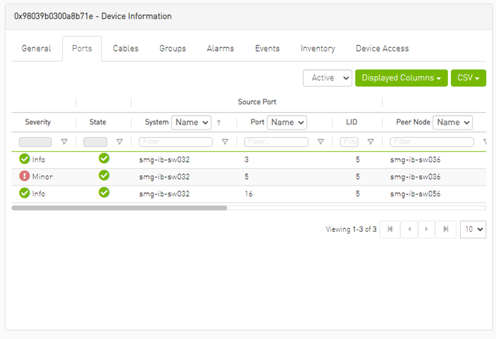
Ports Tab
This tab provides a list of the ports connected to this device in a tabular format.
Ports Data
|
Data Type |
Description |
|
Port Number |
The number of ports on device. |
|
Node |
The node name/GUID/IP that the port belongs to. Note that you can choose the node label (name/GUID/IP) using the drop-down menu available above the Ports data table. |
|
Health |
Health of the port reflecting the highest alarm severity. Please refer to the Health States table. |
|
State |
Indicates whether the port is connected (active or inactive). |
|
LID |
The local identifier (LID) of the port. |
|
MTU |
Maximum Transmission Unit of the port. |
|
Speed 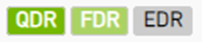
|
Lists the highest value of active, enabled and supported speeds in icons indicating their status:
|
|
Width 
|
Lists the highest value of active, enabled and supported widths in icons indicating their status:
|
|
Peer |
The GUID of the device the port is connected to. |
|
Peer Port |
The name of the port that is connected to this port. |
Cables Tab
This tab provides a list of the cables connected to this device in a tabular format.

Cables Data
|
Data Type |
Description |
|
Basic Information |
|
|
Health |
Health of the cable reflecting the highest alarm severity. Please refer to the Health States table. |
|
Serial Number |
Serial number of the cable. |
|
Identifier |
Identifier of the cable. |
|
Source Port Information |
|
|
Source GUID |
GUID of the source port the cable is connected to. |
|
Source Port |
The number of the source port the cable is connected to. |
|
Destination Port Information |
|
|
Destination GUID |
GUID of the destination port the cable is connected to. |
|
Destination Port |
The number of the destination port the cable is connected to. |
|
Advanced Information |
|
|
Revision |
Revision of the cable. |
|
Link Width |
The maximum link width of the cable. |
|
Part Number |
Part number of the cable. |
|
Technology |
The transmitting medium of the cable: copper/optical/etc. |
|
Length |
The cable length in meters. |
Groups Tab
This tab provides a list of the groups to which the selected device belongs.
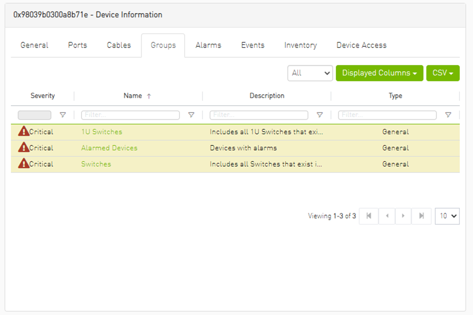
Groups Data
|
Data Type |
Description |
|
Severity |
Aggregated severity level of the group (the highest severity level of all group members). |
|
Name |
Name of the group. |
|
Description |
Description of the group. |
|
Type |
Type of the group: General/Rack. |
Alarms Tab
This tab provides a list of all UFM alarms related to the selected device.
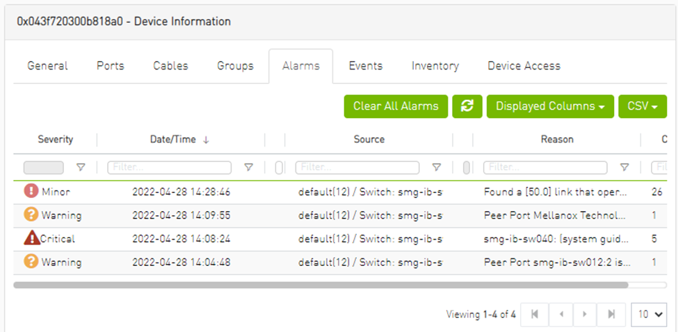
Alarms Data
|
Data Type |
Description |
|
Alarms ID |
Alarm identifier. |
|
Source |
Source object (device/port) on which the alarm was triggered. |
|
Severity |
The severity of the alarm. |
|
Description |
Description of the alarm. |
|
Date/Time |
The time when the alarm was triggered. |
|
Reason |
Reason for the alarm. |
|
Count |
Number of instances that the alarm occurred on the related source object. |
Events Tab
This tab provides a list of the UFM events that are related to the selected device.
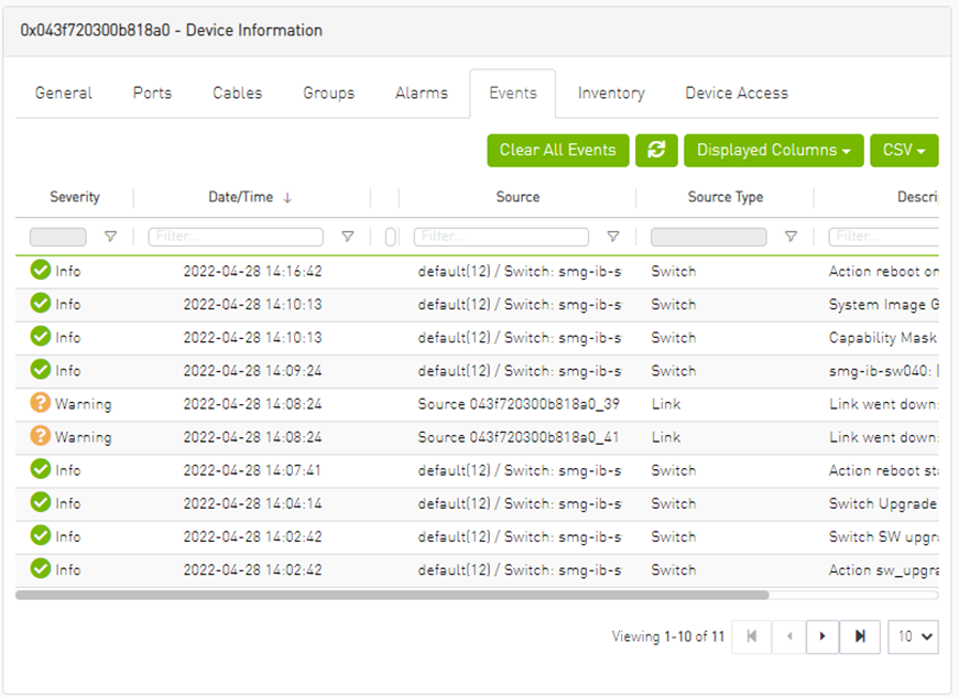
Events Data
|
Data Type |
Description |
|
Severity |
Event severity – Info, Warning, Error, Critical or Minor. |
|
Event Name |
The name of the event. |
|
Source |
The source object (device/port) on which the event was triggered. |
|
Date/Time |
The time when the event was triggered. |
|
Category |
The category of the event indicated by icons. Hovering over the icon will display the category name. |
|
Description |
Description of the event. Full description can be displayed by hovering over the text. |
Inventory Tab
This tab provides a list of the device’s modules with information in a tabular format.
This tab is available for switches only.
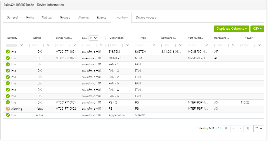
Inventory Data
|
Data Type |
Description |
|
Severity/Health |
Health of the module reflecting the highest alarm severity. Please refer to the Health States table. |
|
Status |
The module status. |
|
Serial Number |
Serial number of the module. |
|
System |
Name of the device. |
|
Description |
Description of the module. |
|
Type |
Type of the module: spine/line/etc. |
|
Software Version |
Firmware version installed on the module. |
|
Part Number |
Part number of the module. |
|
Hardware Version |
Hardware version of the module. |
|
Power |
Power supply of the PSU. |
HCAs Tab
This tab provides a list of the device’s HCAs with information in a tabular format.
This tab is available for hosts only.
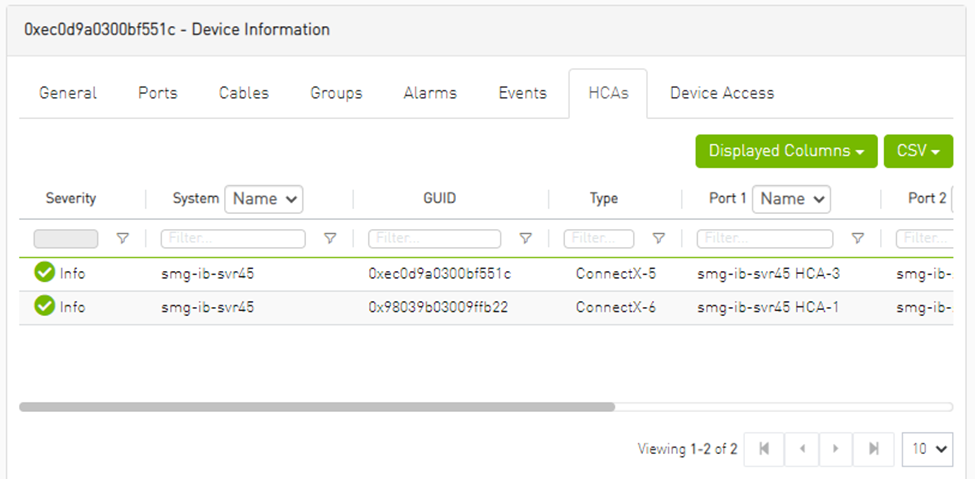
|
Data Type |
Description |
|
Health |
Health of the HCA reflecting the highest alarm severity. Please refer to the Health States table. |
|
Name |
HCA Index |
|
GUID |
HCA GUID |
|
Type |
HCA Type |
|
Port GUID |
HCA ports GUIDs |
|
PSID |
HCA PSID |
|
FW Version |
HCA firmware version |
Device Access Tab
This tab allows for managing the access credentials of the selected device for remote accessibility. To be able to set access credentials for the device, a device IP must be set either by installing UFM Agent on the device, or by manually setting the IP under IP Address Settings (IP is now supported with v4 and v6).
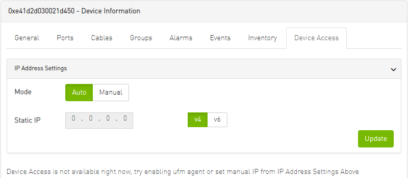
After manually setting the IP address of NVIDIA® Mellanox® InfiniScale IV® and SwitchX® based switches, UFM will first validate the new IP before setting it.
To edit your device access credentials
Select the preferred protocol tab:
SSH – allows you to define the SSH parameters to open an SSH session on your device (available for nodes and switches)
IPMI – allows you to set the IPMI parameters to open an IPMI session on your device for remote power control (available for nodes only)
HTTP – allows you to define the HTTP parameters to open an HTTP session on your device (available for switches only)
Click Update to save your changes.
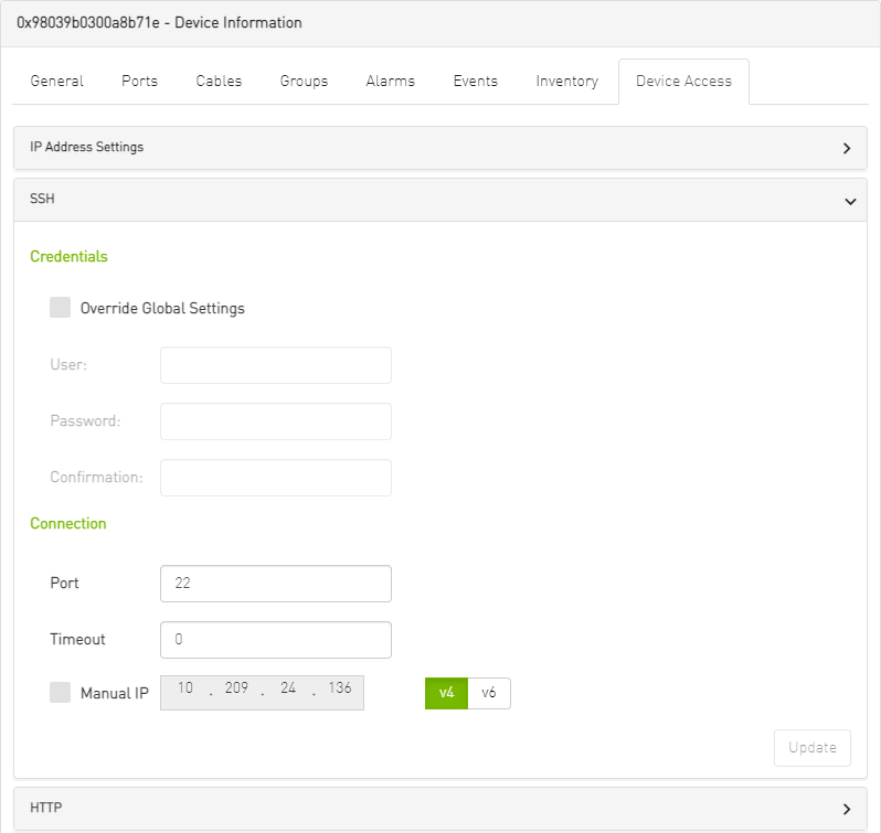
Device Access Credentials Parameters
|
Field |
Description |
|
User |
Fill in or edit the computer user name. |
|
Password |
Enter the device password. |
|
Confirmation |
Enter the device password a second time to confirm. |
|
Manual IP |
Enter the device IP address (could be IPv4/IPv6). |
|
Port |
Enter the port number. |
|
Timeout |
Enter the connection timeout (in seconds) for the device specific protocol (SSH/HTTP/IPMI). |
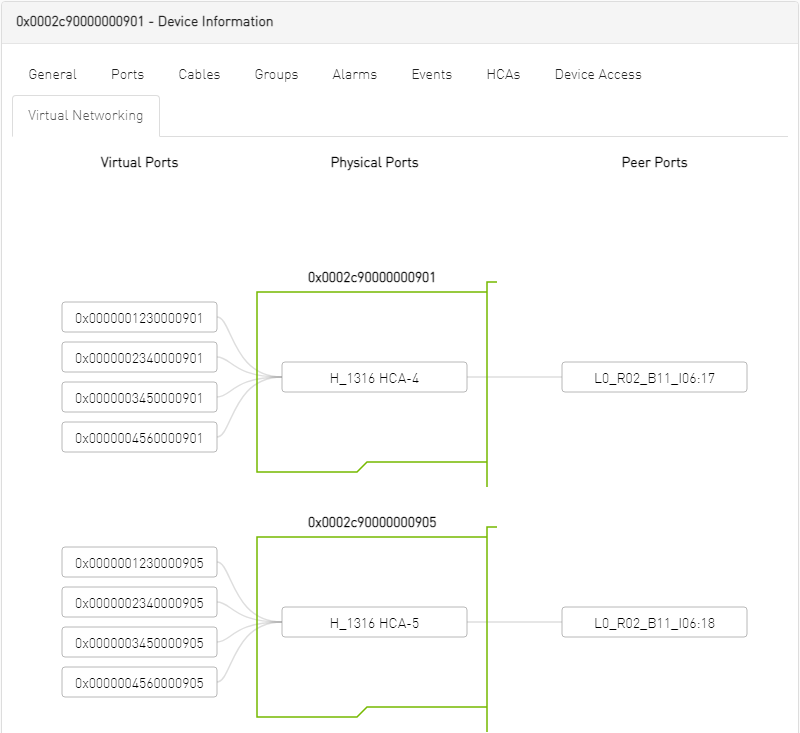
Virtual Networking Tab
This tab displays a map containing the HCAs for the selected device, and the ports and virtual ports it is connected to.