NDT Plugin
NDT plugin is a self-contained Docker container with REST API support managed by UFM. The NDT plugin introduces the following capabilities:
NDT topology comparison: Allows the user to compare InfiniBand fabric managed by the UFM and NDT files which are used for the description of InfiniBand clusters network topology.
Verifies the IB fabric connectivity during cluster bring-up.
Verifies the specific parts of IB fabric after component replacements.
Automatically detects any changes in topology.
Subnet Merger - Expansion of the fabric based on NDT topology files
Allows users to gradually extend the InfiniBand fabric without causing any disruption to the running fabric. The system administrator should prepare the NDT topology files, which describe the InfiniBand fabric extensions. Then, an intuitive and user-friendly UI wizard facilitates the topology extension process with a step-by-step guidance for performing necessary actions.
The Subnet Merger tool verifies the fabric topology within a predefined NDT file, and reports issues encountered for immediate resolution.
Once the verification results are acceptable by the network administrator, the tool creates a topoconfig file to serve as input for OpenSM. This allows setting the physical port states of the designated boundary ports as desired (physical ports can be set as disabled or no-discover).
Once the topoconfig file is deployed, the IB network can be extended and verified for the next IB extension.
The following are the possible ways NDT plugin can be deployed:
On UFM Appliance
On UFM Software
For detailed instructions on how to deploy the NDT plugin refer to this page.
Following authentication types are supported:
basic (/ufmRest)
client (/ufmRestV2)
token (/ufmRestV3)
The following REST APIs are supported:
Topodiff
GET /help
GET /version
POST /upload_metadata
GET /list
POST /compare
POST /cancel
GET /reports
GET /reports/<report_id>
POST /delete
Subnet Merger
GET /merger_ndts_list
GET /merger_ndts_list/<ndt_file_name>
POST /merger_upload_ndt
POST /merger_verify_ndt
GET /merger_verify_ndt_reports
GET /merger_verify_ndt_reports/<report_id>
POST /merger_update_topoconfig
POST /merger_deploy_ndt_config
POST /merger_update_deploy_ndt_config
POST /merger_delete_ndt
GET /merger_deployed_ndt
POST /merger_create_topoconfig
For detailed information on how to interact with NDT plugin, refer to the NVIDIA UFM Enterprise > Rest API > NDT Plugin REST API.
NDT is a CSV file containing data relevant to the IB fabric connectivity. The NDT plugin extracts the IB connectivity data based on the following fields:
Start device
Start port
End device
End port
Link type
Switch to Switch NDT
By default, IB links are filtered by:
Link Type is Data
Start Device and End Device end with IBn, where n is a numeric value.
For TOR switches, Start port/End port field should be in the format Port N, where N is a numeric value.
For Director switches, Start port/End port should be in the format Blade N_Port i/j, where N is a leaf number, i is an internal ASIC number and j is a port number.
Examples:
|
Start Device |
Start Port |
End Device |
End Port |
Link Type |
|
DSM07-0101-0702-01IB0 |
Port 21 |
DSM07-0101-0702-01IB1 |
Blade 2_Port 1/1 |
Data |
|
DSM07-0101-0702-01IB0 |
Port 22 |
DSM07-0101-0702-01IB1 |
Blade 2_Port 1/1 |
Data |
|
DSM07-0101-0702-01IB0 |
Port 23 |
DSM07-0101-0702-02IB1 |
Blade 3_Port 1/1 |
Data |
|
DSM09-0101-0617-001IB2 |
Port 33 |
DSM09-0101-0721-001IB4 |
Port 1 |
Data |
|
DSM09-0101-0617-001IB2 |
Port 34 |
DSM09-0101-0721-001IB4 |
Port 2 |
Data |
|
DSM09-0101-0617-001IB2 |
Port 35 |
DSM09-0101-0721-001IB4 |
Port 3 |
Data |
Switch to Host NDT
NDT is a CSV file containing data not only relevant to the IB connectivity.
Extracting the IB connectivity data is based on the following five fields:
Start device
Start port
End device
End port
Link type
IB links should be filtered by the following:
Link type is "Data".
"Start Device" or "End Device" end with IBN, where N is a numeric value.
The other Port should be based on persistent naming convention: ibpXsYfZ, where X, Y and Z are numeric values.
For TOR switches, Start port/End port field will be in the format Port n, where n is a numeric value.
For Director switches, Start port/End port will be in the format Blade N_Port i/j, where N is a leaf number, i is an internal ASIC number and j is a port number.
Examples:
|
Start Device |
Start Port |
End Device |
End Port |
Link Type |
|
DSM071081704019 |
DSM071081704019 ibp11s0f0 |
DSM07-0101-0514-01IB0 |
Port 1 |
Data |
|
DSM071081704019 |
DSM071081704019 ibp21s0f0 |
DSM07-0101-0514-01IB0 |
Port 2 |
Data |
|
DSM071081704019 |
DSM071081704019 ibp75s0f0 |
DSM07-0101-0514-01IB0 |
Port 3 |
Data |
Other
Comparison results are forwarded to syslog as events. Example of /var/log/messages content:
Dec 9 12:32:31 <server_ip> ad158f423225[4585]: NDT: missing in UFM "SAT111090310019/SAT111090310019 ibp203s0f0 - SAT11-0101-0903-19IB0/15"
Dec 9 12:32:31 <server_ip> ad158f423225[4585]: NDT: missing in UFM "SAT11-0101-0903-09IB0/27 - SAT11-0101-0905-01IB1-A/Blade 12_Port 1/9"
Dec 9 12:32:31 <server_ip> ad158f423225[4585]: NDT: missing in UFM "SAT11-0101-0901-13IB0/23 - SAT11-0101-0903-01IB1-A/Blade 08_Port 2/13"
For detailed information about how to check syslog, please refer to the NVIDIA UFM-SDN Appliance Command Reference Guide > UFM Commands > UFM Logs.
Minimal interval value for periodic comparison in five minutes.
In case of an error the clarification will be provided.
For example, the request “POST /compare” without NDTs uploaded will return the following:
response code: 400
Response:
            {
  "error": [
    "No NDTs were uploaded for comparison"
  ]
}
Configurations could be found in “ufm/conf/ndt.conf”
Log level (default: INFO)
Log size (default: 10240000)
Log file backup count (default: 5)
Reports number to save (default: 10)
NDT format check (default: enabled)
Switch to switch and host to switch patterns (default: see NDT format section)
For detailed information on how to export or import the configuration, refer to the NVIDIA UFM-SDN Appliance Command Reference Guide > UFM Commands > UFM Configuration Management.
Logs could be found in “ufm/logs/ndt.log”.
For detailed information on how to generate a debug dump, refer to the NVIDIA UFM-SDN Appliance Command Reference Guide > System Management > Configuration Management > File System.
The Subnet Merger tool facilitates the seamless expansion of the InfiniBand fabric based on Non-Disruptive Topology (NDT) files. This section outlines the process of extending the fabric while ensuring uninterrupted operation. The tool operates through an intuitive UI wizard, guiding users step-by-step in extending the fabric topology.
The Subnet Merger tool enables the gradual expansion of the InfiniBand fabric without causing disruptions to the existing network. To achieve this, system administrators need to prepare NDT topology files that describe the planned fabric extensions. The tool offers an intuitive UI wizard that simplifies the extension process.
Functionality
NDT Topology File Verification: The Subnet Merger tool verifies the InfiniBand fabric topology specified in a predefined NDT file. During this verification, any issues encountered are reported to the user for immediate resolution. This step ensures the integrity of the planned fabric extension.
Topology Extension Preparation: Upon successful verification of the NDT topology file, the tool generates a comprehensive verification report. The network administrator reviews this report and ensures its acceptability.
Topoconfig File Generation: After obtaining acceptable verification results, the tool generates a topoconfig file. This file serves as input for OpenSM, the Subnet Manager for InfiniBand fabrics. The topoconfig file allows the network administrator to define the desired physical port states for designated boundary ports. These states include "disabled" or "no-discover."
Fabric Extension and Verification: With the topoconfig file prepared, the Subnet Merger tool initiates the deployment of the extended fabric configuration. The tool ensures that the defined physical port states are implemented. Once the extension is in place, the IB network can be extended further as needed. The fabric extension is executed while maintaining the operational stability of the existing network.
Conclusion: The Subnet Merger tool offers a reliable and user-friendly solution for expanding InfiniBand fabrics using NDT topology files. By following the steps provided in the intuitive UI wizard, system administrators can seamlessly extend the fabric while adhering to predefined physical port states. This tool ensures the smooth operation of the fabric throughout the expansion process, eliminating disruptions and enhancing network scalability.
Subnet Merger Flow
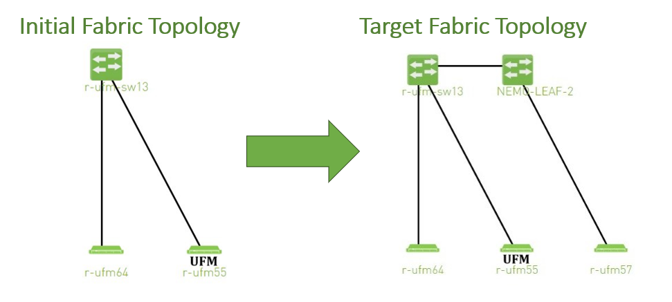
Create NDT, file that describes initial topology with definition of boundary ports. Boundary ports – switch ports that will be used for fabric extension. In our case it will be r-ufm-sw13 switch ports number 1 and 3. In NDT file those ports should be defined as boundary and disabled:
rack #,U height,#Fields:StartDevice,StartPort,StartDeviceLocation,EndDevice,EndPort,EndDeviceLocation,U height_1,LinkType,Speed,_2,Cable Length,_3,_4,_5,_6,_7,State,Domain ,,MF0;r-ufm-sw13:MQM8700/U1,Port
1,,,,,,,,,,,,,,,Disabled,Boundary ,,MF0;r-ufm-sw13:MQM8700/U1,Port30,,r-ufm55 mlx5_1,Port1,,,,,,,,,,,,Active,In-Scope ,,MF0;r-ufm-sw13:MQM8700/U1,Port29,,r-ufm55 mlx5_0,Port1,,,,,,,,,,,,Active,In-Scope ,,MF0;r-ufm-sw13:MQM8700/U1,Port26,,r-ufm64 mlx5_0,Port1,,,,,,,,,,,,Active,In-Scope ,,MF0;r-ufm-sw13:MQM8700/U1,Port3,,,,,,,,,,,,,,,Disabled,BoundaryUpload a new NDT topology file which describes the desired topology. Before deploying to UFM, the new NDT topology file should be verified against the existing topology – to find out mismatches and problems.
After the verification, the plugin generates reports including information about:
Duplicated GUIDs
Misswired links
Non-existent links in the pre-defined NDT files
Links that exist in the fabric and not in the NDT file
Following the issues detected in the plugin reports, the network administrator changes the NDT file or the fabric. The verification process can be repeated as many times as necessary until the network administrator is satisfied with the results.
If the NDT verification results are satisfactory, a topoconfig file is generated and can be deployed to the UFM server to be used as configuration input for OpenSM. Topoconfig file should be located at /opt/ufm/files/conf/opensm/topoconfig.cfg on UFM server. By sending SIGHUP signal to opensm it forced to read configuration and to deploy it. In topoconfig file at this stage boundary ports will be defined as Disabled.
Example of topoconfig.cfg:
0xb83fd2030080302e,1,-,-,Any, Disabled0xb83fd2030080302e,30,0xf452140300280081,1,Any,Active0xb83fd2030080302e,29,0xf452140300280080,1,Any,Active0xb83fd2030080302e,26,0xf452140300280040,1,Any,Active0xb83fd2030080302e,3,-,-,Any, DisabledNext stage is to extend the fabric. Prepare separately new subnet that will be added to the existing fabric and, once it is ready, connect to the boundary ports, that are defined as Disabled in configuration file, so newly added subnet will not be discovered by opensm and will not affect in any way current setup functionality.
Once new subnet connected to the fabric - prepare next NDT file, that contains setup, that describes current fabric with extended, when previously defined as boundary ports defined as Active and if planned to continue with extension new ports defined as boundary.
For example port number 9 of switch r-ufm-sw13:rack #,U height,#Fields:StartDevice,StartPort,StartDeviceLocation,EndDevice,EndPort,EndDeviceLocation,U height_1,LinkType,Speed,_2,Cable Length,_3,_4,_5,_6,_7,State,Domain ,,MF0;r-ufm-sw13:MQM8700/U1,Port
1,,NEMO-LEAF-2,Port1,,,,,,,,,,,,Active,In-Scope ,,MF0;r-ufm-sw13:MQM8700/U1,Port30,,r-ufm55 mlx5_1,Port1,,,,,,,,,,,,Active,In-Scope ,,MF0;r-ufm-sw13:MQM8700/U1,Port29,,r-ufm55 mlx5_0,Port1,,,,,,,,,,,,Active,In-Scope ,,NEMO-LEAF-2,Port11,,r-ufm57 mlx5_0,Port1,,,,,,,,,,,,Active,In-Scope ,,MF0;r-ufm-sw13:MQM8700/U1,Port26,,r-ufm64 mlx5_0,Port1,,,,,,,,,,,,Active,In-Scope ,,NEMO-LEAF-2,Port1,,MF0;r-ufm-sw13,Port1,,,,,,,,,,,,Active,In-Scope ,,MF0;r-ufm-sw13:MQM8700/U1,Port3,,NEMO-LEAF-2,Port3,,,,,,,,,,,,Active,In-Scope ,,NEMO-LEAF-2,Port3,,MF0;r-ufm-sw13,Port3,,,,,,,,,,,,Active,In-Scope ,,MF0;r-ufm-sw13:MQM8700/U1,Port9,,,,,,,,,,,,,,,Disabled,BoundaryAfter new subnet connected physically to the fabric, in opensm configuration file (topoconfig.cfg) boundary ports previously defined as Disabled should be set as No-discover. Example:
0xb83fd2030080302e,1,-,-,Any,No-discover0xb83fd2030080302e,30,0xf452140300280081,1,Any,Active0xb83fd2030080302e,29,0xf452140300280080,1,Any,Active0xb83fd2030080302e,26,0xf452140300280040,1,Any,Active0xb83fd2030080302e,3,-,-,Any,No-discoverUpdated file should be deployed to UFM. In case boundary ports will be defined as No-discover – fabric, connected beyond those ports will not be discovered by opensm, but all the ibutils (ibdiagnet…) could send mads beyond those ports to newly added subnet - so NDT file verification for extended setup could be performed.
Upload new NDT file and run verification for this file. Fix problems detected by verification. Once satisfied with results – deploy configuration to UFM.
Example of topoconfig file for extended setup:0xb83fd2030080302e,1,0x98039b0300867bba,1,Any,Active0xb83fd2030080302e,30,0xf452140300280081,1,Any,Active0xb83fd2030080302e,29,0xf452140300280080,1,Any,Active0x98039b0300867bba,11,0x248a0703009c0066,1,Any,Active0xb83fd2030080302e,26,0xf452140300280040,1,Any,Active0x98039b0300867bba,1,0xb83fd2030080302e,1,Any,Active0xb83fd2030080302e,3,0x98039b0300867bba,3,Any,Active0x98039b0300867bba,3,0xb83fd2030080302e,3,Any,Active0xb83fd2030080302e,9,-,-,Any,DisabledRepeat previous steps if need to perform additional setup extension.
Subnet Merger UI
Bring-Up Merger Wizard
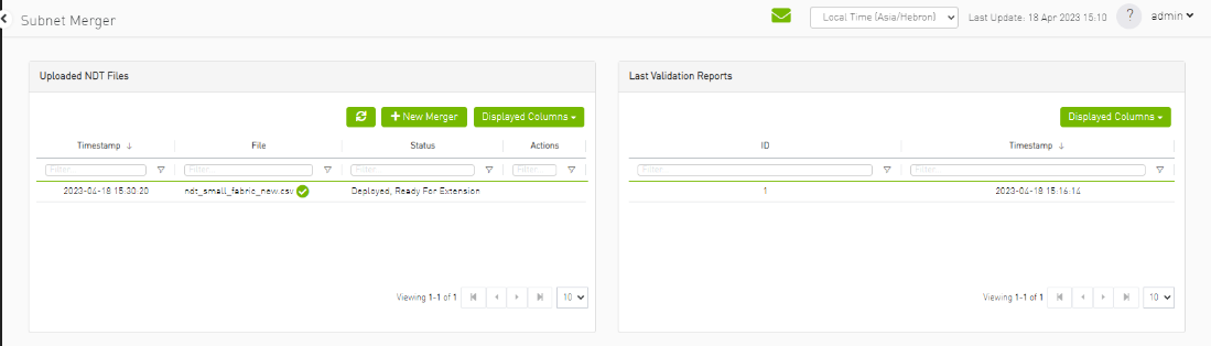
Add the NDT plugin to UFM by loading the plugin's image through Settings->Plugins Management. A new item will appear in the main left navigator menu of the UFM labeled "Subnet Merger".
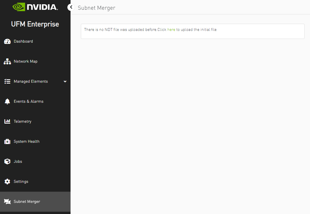
Access "Subnet Merger" to initiate the bring-up wizard.
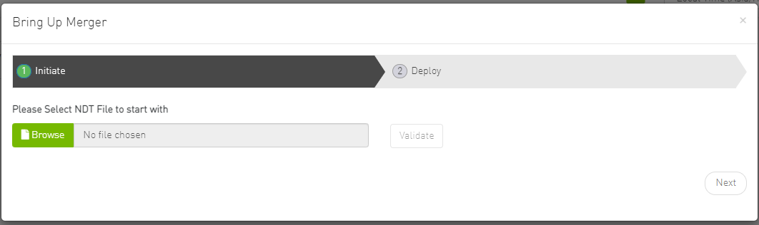
The wizard will guide you through the process, containing the following steps:
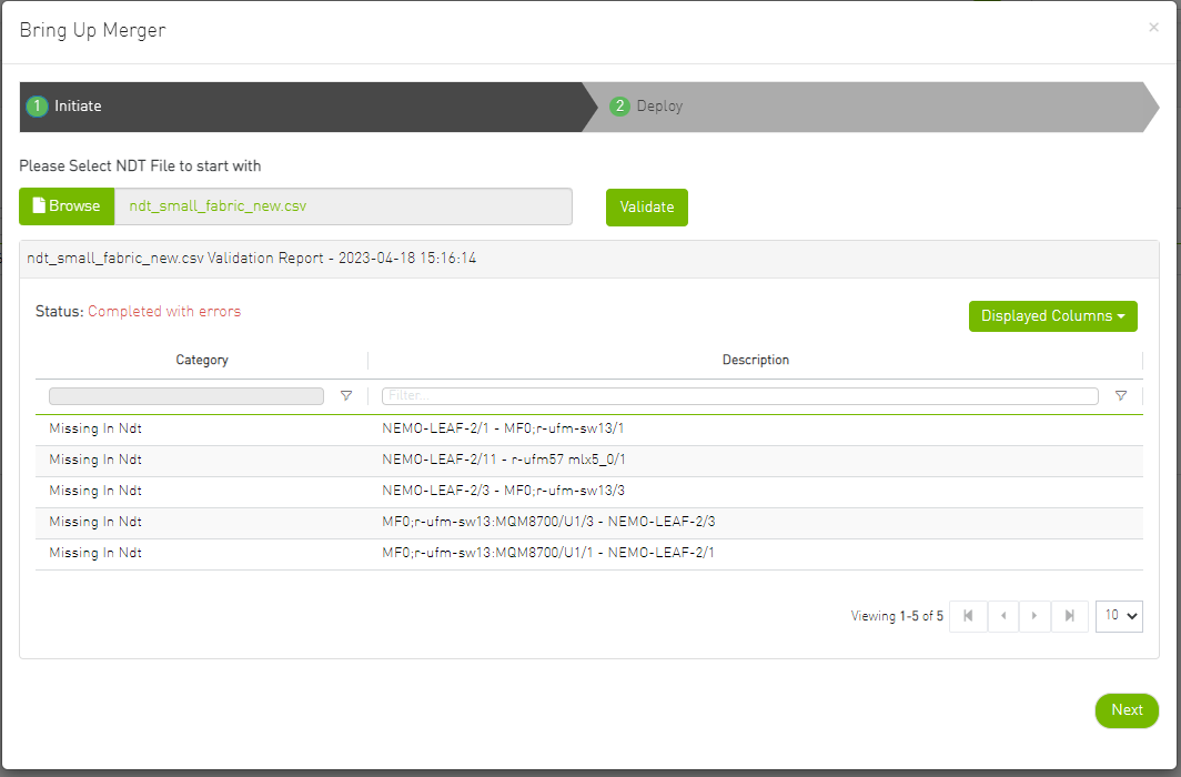
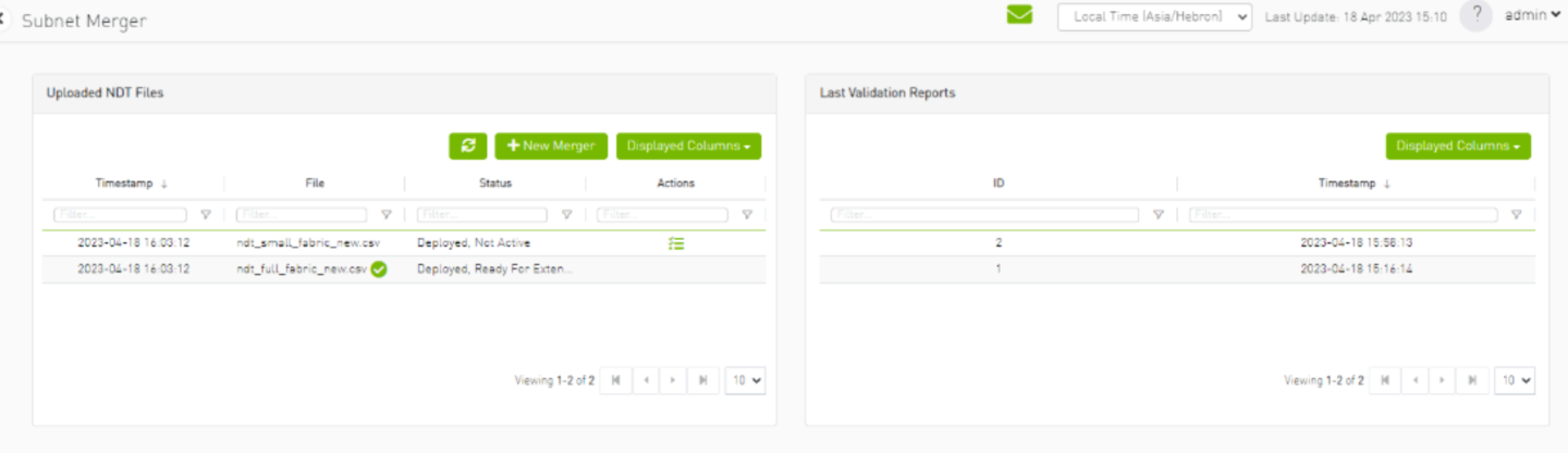
Upload the initial NDT tab and validate it.
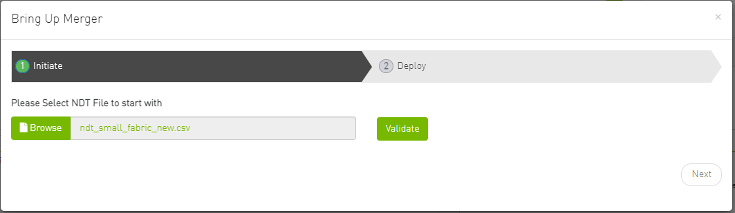
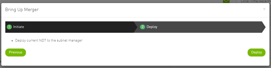
Once you are satisfied with the results of the validation in the previous tab, you can proceed to deploy the file.
New Subnet Merger
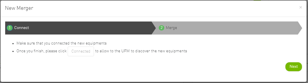
Once you have successfully deployed the initial NDT file, you can initiate a new merger process by clicking the "New Merger" button.
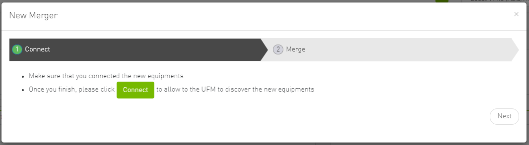
"Connect" Tab, it is important to physically connect the new equipment and confirm the connection. Then, click on a button which will open the boundary ports, change their state from Disabled to No-discover, and then deploy the active file again.
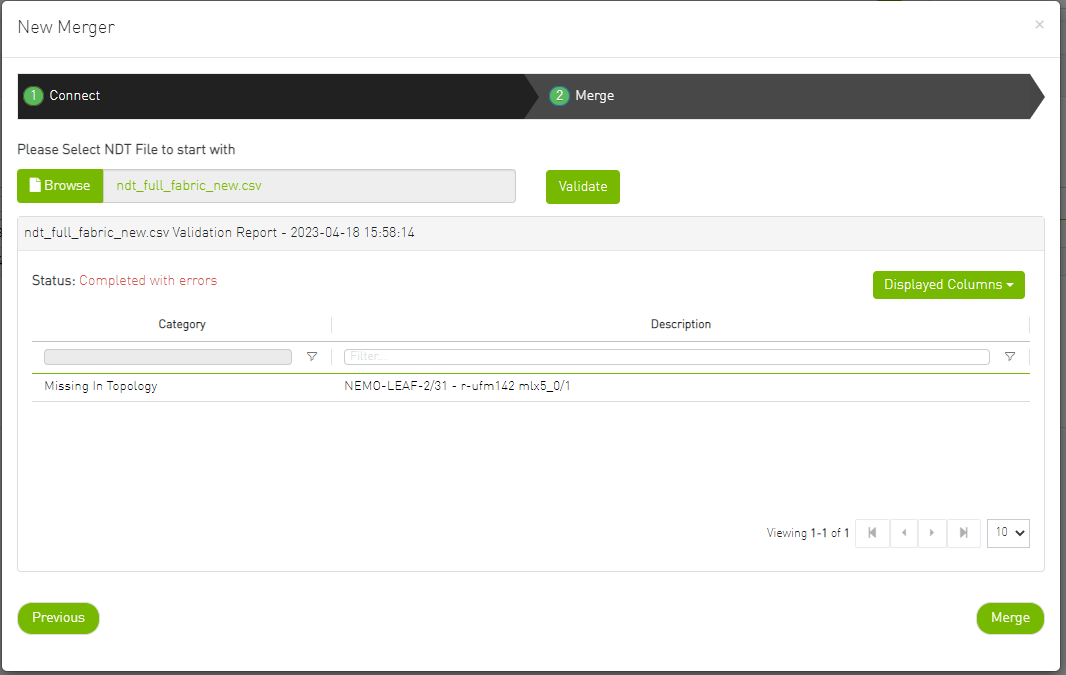
"Merge" Tab: Once the new equipment is connected and the boundary ports are updated, upload a new NDT file that includes both the current and newly added equipment, along with their boundary ports for future merges. Please note that you cannot merge the file if there are duplicate GUIDs in the report's results.
After completing the merge wizard, and if necessary, you can further proceed to extend the IB fabric.
Extending the InfiniBand Setup via Subnet Merger
The following instructions outline the necessary steps for expanding the InfiniBand setup or fabric using subnet merging.
Step 1: NDT File Upload (Repeatable)
Upload the NDT file, performing this action as many times as required, especially when addressing file-related issues.
Step 2: NDT File Validation and Verification (Repeatable)
Validate the NDT file, a process that can be repeated multiple times, particularly after fixing fabric topology or NDT file errors. After initiating this call, you will obtain a validation report ID. The progress of this process is asynchronous, with the report's status initially indicated as "running." Once the report is completed, the status will change to either "Successfully completed" or "Completed with errors."
Step 3: Retrieving and Monitoring the Validation Report
Retrieve the validation report by its corresponding ID, running this step through continuous polling until the report reaches completion.
Step 4: Review and Potential Fixes
Inspect the report and address any necessary fixes to either the NDT file or the topology. Should changes be made to the file, upload the corrected NDT file anew. Alternatively, in case of topology has changed, repeat the verification process.
Step 5: Topology Deployment to UFM
Deploy the verified topology to UFM once you are satisfied with the verification outcomes.
Step 6: Adjusting Boundary Ports and Deployment
Following the physical connection of the setup extension, change the boundary ports' state from "Disabled" to "No-discover."
Step 7: Uploading Updated Topoconfig File
Deploy the updated topoconfig file to the UFM server.
Step 8: Next NDT File Upload (Combined Fabric and Extension)
Upload the next NDT file, which consolidates the current fabric and extension components.
Step 9: NDT File Verification
Conduct the NDT file verification process.
Step 10: Reviewing Verification Report
Review the verification report.
Step 11: Addressing Setup or NDT File Issues
If necessary, make necessary adjustments to the setup or NDT file.
Step 12: Final Configuration Deployment
Once content with the modifications, proceed to deploy the configuration to UFM.
Step 13: Iterative Workflow
Repeat this flow as many times as needed to further the expansion process.