ORBDescExtractor#
Overview#
The ORB (Oriented FAST and Rotated BRIEF) algorithm is a complete feature detection and description pipeline that detects keypoints across multiple scales of an input image pyramid and extracts binary descriptors for each detected keypoint. The algorithm consists of two main stages: feature detection using the FAST (Features from Accelerated Segment Test) algorithm to find corners at different pyramid levels, followed by descriptor extraction using a rotation-invariant version of BRIEF (Binary Robust Independent Elementary Features) called rBRIEF [1].
The ORBDescExtractor operator implements the second stage of the complete ORB pipeline - the descriptor extraction
stage. It takes pre-detected keypoints as input and generates 256-bit binary descriptors (32 bytes) for each keypoint [2].
These descriptors are commonly used in computer vision applications such as feature matching, object detection, and
image registration.
The operator supports two modes for the descriptor: BRIEF and rBRIEF. A flag disableRBRIEFFlag is used to select the mode.
The original BRIEF descriptor is fast and compact but lacks rotation invariance. When an image is rotated, the same
keypoint produces different descriptors, making matching difficult.
The rBRIEF variant addresses this limitation by computing the dominant orientation of each keypoint,
then rotating the sampling patterns accordingly.
By doing this, the same keypoint produces similar descriptors under arbitrary rotation,
making rBRIEF significantly more robust to image rotation while maintaining the computational
efficiency of the original BRIEF algorithm.
After rectifying the sampling patterns by the keypoint orientation, the BRIEF descriptor is generated by performing 256 binary tests on a patch surrounding the keypoint and combining their results into a 256-bit string. Each binary test is defined as follows: two pixels on a patch are compared by intensity, and if the first has less intensity than the second, a value of 1 is set; otherwise, a value of 0 is set. The pixel locations for these tests are pre-determined by a carefully designed pattern that minimizes correlation and increases variance.
Implementation#
Limitations#
The current implementation only supports feature points from a single image, rather than from multiple levels of the image pyramid. This limitation only affects how image patch around each keypoint is fetched, without any other impact on the computation implementation.
The ORB descriptor extractor supports multiple image formats and border handling methods. All supported image formats are: U8, Y8, Y8_ER, S8, U16, Y16, Y16_ER, and S16. Supported border types are: constant padding and border pixel extension (BPE).
Batch Processing#
The operator supports an arbitrary number of keypoints. Keypoints are processed in tiles, with each tile containing a batch of keypoints. The batch size is chosen as the length of a single vector for its underlying data type on the VPU, to facilitate vectorized math calculations throughout the process. Specifically, the batch sizes are:
8-bit data types (U8, Y8, Y8_ER, S8): batch size is 32
16-bit data types (U16, Y16, Y16_ER, S16): batch size is 16
When the number of keypoints is not exactly a multiple of the tile size, the last tile is not full. For input and output data flows we use the actual number of remaining keypoints in the last tile, while for computations we use the full tile size. This is justified by the fact that performance of the implementation is bounded by DMA latency.
Data Flow Configuration#
For each tile of keypoints, Three data flows are involved:
Input SequenceDataFlow (SQDF): reads a batch of floating-point keypoint coordinates, saved in continuous XY-interleaved format.
Input GatherScatterDataFlow (GSDF): reads a batch of image patches around keypoints, by setting
numTilesPerTrigger = batch_size.Output SequenceDataFlow (SQDF): writes a batch of descriptors.
The input data flows must be done in order, and a preprocessing step is required in between. To be specific, the SQDF read data flow first loads the keypoint coordinates in floating-point. Then a kernel function is called to truncate the floating-point coordinates into integer coordinates by vectors. After that, the GSDF read data flow fetches image patches centered at the integer coordinates.
The image patch size around each keypoint is 39x39 pixels, which is large enough to cover both the circle for orientation calculation and sampling patterns under arbitrary rotation. See Figure 2: Points used for calculating the intensity centroid and Figure 3: Visualization of the ORB pattern pairs for demonstrations of the regions involved in the orientation calculation and sampling patterns.
Math Computations#

Figure 1: ORB descriptor extractor main loop flow chart#
A flow chart for a full cycle in the main loop is shown above. Note that in the flow chart, the input, computations, and output stages are drawn sequentially to illustrate all the steps in the main loop. In the implementation, the input and output data flows are pipelined with computations by applying the ping-pong method.
The computation stage differs between the rBRIEF and BRIEF modes. For the rBRIEF algorithm, the following math computations are performed:
Calculate the orientation of each keypoint by intensity centroid
Normalize the orientation vector to get the rotation matrix
Rotate the ORB sampling patterns and add offsets for 2D lookup
Perform 2D lookup
Generate descriptors by binary tests
For the BRIEF algorithm, steps 1-3 are skipped. However, additional offsets still need to be added to the ORB sampling patterns before 2D lookup.
Each step in the math computations is explained in detail below.
Orientation by Intensity Centroid#
In rBRIEF, the orientation of each keypoint is obtained by computing the intensity centroid of a neighborhood around the keypoint. The neighborhood is determined by points inside a circle of radius 15, shown below in Figure 2: Points used for calculating the intensity centroid.
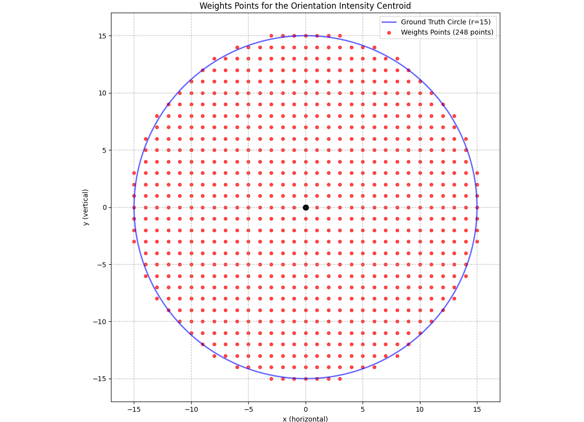
Figure 2: Points used for calculating the intensity centroid#
The intensity centroid is defined as \((m_{10}/m_{00}, m_{01}/m_{00})\), where
The intensity centroid is then used to derive the orientation angle \(\theta\) by:
which is left to the next step. In this step, we only calculate the moments \(m_x = m_{10}\) and \(m_y = m_{01}\).
The moments in the x and y directions can be written explicitly as:
We use vdotp4x2 instructions to accelerate the dot product between pixel values and x and y coordinates.
The x and y coordinates inside the circle are pre-calculated and stored in a header file,
so that they can be directly loaded for each tile.
Generating Rotation Matrix#
The moments in the x and y directions are normalized to get the sin and cos values of the orientation angle.
The rotation matrix is then:
The sin and cos values of the orientation angle are first calculated in floating-point, and then converted to fixed-point with Q.6 precision, allowing for integer instructions to accelerate the rotation later.
Pattern Rotation / Shifting#
In the original BRIEF algorithm, pixel values are evaluated at 512 sampling patterns, then 256 binary tests are performed to generate a 256-bit descriptor. In the rBRIEF algorithm, these sampling patterns are first rotated by the orientation angle to ensure rotation invariance. Specifically, for each ORB sampling pattern, the coordinates are transformed by the rotation matrix:
The matrix multiplication is done in fixed-point arithmetic, calling the vdotp2_bbh instruction.
For both BRIEF and rBRIEF modes, to get the final indices for 2D lookup, extra offsets are added to the patterns to shift coordinates to the image patch start. The offsets come from two sources:
Offsets of the image patch center, which is (19, 19) for a 39x39 patch size.
Offsets for table address alignment
The batch of image patches are stored in a 2D array, with each row containing continuous data of one patch.
The line pitch of this 2D array is aligned to \(64k+2\) pixels to support transpose load when calculating the intensity centroid,
where \(k\) is the smallest positive integer such that \(64k+2\) is greater than the original line pitch.
However, 2D lookup by CupvaSampler only supports table address offset aligned to 64 bytes.
To tackle this issue, we pretend that we have a line pitch of \(64k\) pixels instead,
by setting inputAdv to \(64k\) in CupvaSamplerInput and adding an offset to X coordinates by \(2 \times \text{row_index}\).
Here \(\text{row_index}\) is the index of the row in the 2D array of image patches, which is indeed the keypoint index in the tile.
Visualization of the ORB sampling patterns without rotation is shown below, where each pair of points for binary test is drawn as a line.
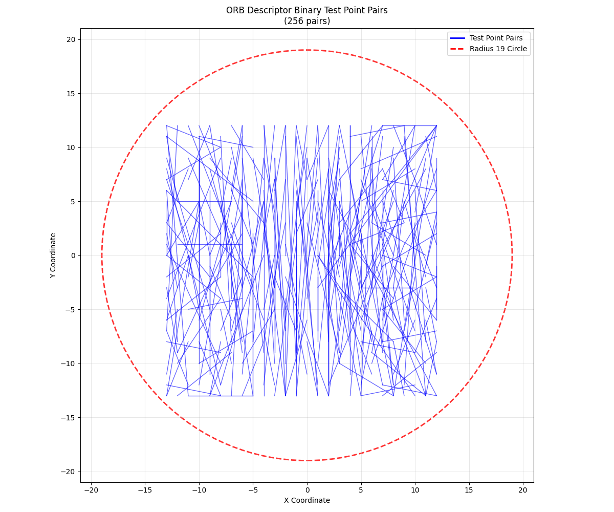
Figure 3: Visualization of the ORB pattern pairs#
2D Lookup for ORB Bit Patterns#
After preparing the coordinates, 2D lookup is carried out by CupvaSampler. For rBRIEF, indices are provided in fixed-point format of Q.6, and rounding for the indices is done internally in CupvaSampler. For BRIEF, indices are already in integer format, and the CupvaSampler performs 2D lookup directly.
Descriptor Calculation#
For each keypoint, the descriptor is a 256-bit binary string, stored as a uint8 vector of length 32. Each bit comes from a binary test between two sampling patterns. A binary test at point \((x_1, y_1)\) and \((x_2, y_2)\) is defined as:
Pixel values for the 512 sampling patterns are fetched in the 2D lookup stage.
256 binary tests are then performed on each pair of patterns. To carry out the binary tests on VPU with vectorization,
the instruction vbitcmp_s is adopted to compare lane values between two vectors.
It gives 1 to greater or equal than cases and pack results into a scalar integer.
Afterwards, to get the desired less than behavior,
the bitwise not operator ~ is applied to the scalar to flip the bit values.
Performance#
Execution Time is the average time required to execute the operator on a single VPU core.
Note that each PVA contains two VPU cores, which can operate in parallel to process two streams simultaneously, or reduce execution time by approximately half by splitting the workload between the two cores.
Total Power represents the average total power consumed by the module when the operator is executed concurrently on both VPU cores.
Idle power is approximately 7W when the PVA is not processing data.
For detailed information on interpreting the performance table below and understanding the benchmarking setup, see Performance Benchmark.
ImageSize |
ImageFormat |
NumFeatures |
DisableRBRIEF |
Execution Time |
Submit Latency |
Total Power |
|---|---|---|---|---|---|---|
1920x1080 |
U8 |
300 |
0 |
0.139ms |
0.028ms |
12.926W |
1920x1080 |
U8 |
300 |
1 |
0.135ms |
0.028ms |
12.926W |
1920x1080 |
U8 |
600 |
0 |
0.232ms |
0.028ms |
13.126W |
1920x1080 |
U8 |
1200 |
0 |
0.424ms |
0.029ms |
13.125W |
1920x1080 |
Y8 |
300 |
0 |
0.139ms |
0.028ms |
12.925W |
1920x1080 |
Y8 |
300 |
1 |
0.134ms |
0.028ms |
12.926W |
1920x1080 |
Y8_ER |
300 |
0 |
0.140ms |
0.028ms |
12.925W |
1920x1080 |
Y8_ER |
300 |
1 |
0.134ms |
0.028ms |
12.926W |
1920x1080 |
S8 |
300 |
0 |
0.140ms |
0.028ms |
12.925W |
1920x1080 |
S8 |
300 |
1 |
0.134ms |
0.028ms |
12.926W |
1920x1080 |
U16 |
300 |
0 |
0.162ms |
0.025ms |
13.026W |
1920x1080 |
U16 |
300 |
1 |
0.156ms |
0.025ms |
13.407W |
1920x1080 |
Y16 |
300 |
0 |
0.162ms |
0.025ms |
12.926W |
1920x1080 |
Y16 |
300 |
1 |
0.157ms |
0.025ms |
12.643W |
1920x1080 |
Y16_ER |
300 |
0 |
0.161ms |
0.025ms |
13.026W |
1920x1080 |
Y16_ER |
300 |
1 |
0.156ms |
0.025ms |
13.027W |
1920x1080 |
S16 |
300 |
0 |
0.163ms |
0.025ms |
13.026W |
1920x1080 |
S16 |
300 |
1 |
0.155ms |
0.025ms |
13.409W |
Reference#
Rublee, E., Rabaud, V., Konolige, K., & Bradski, G. (2011). ORB: An efficient alternative to SIFT or SURF. In 2011 International conference on computer vision (pp. 2564-2571). IEEE. DOI: 10.1109/ICCV.2011.6126544
NVIDIA VPI Documentation: ORB feature detector