Remap#
Overview#
The Remap operator applies a generic geometric transformation to an image using a warp map. For each pixel in the output image, the warp map provides a float coordinate \(\text{warpMap}[i][j] = \{inX, inY\}\) that indicates where to sample from the input image.
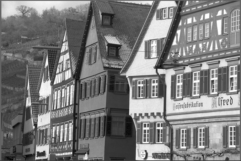
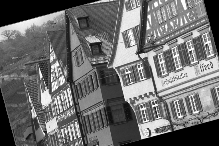
Typical use cases include lens distortion correction, border extension, and conversion between different projections. See the images below, the left one is the input image, and the right one is the output of Remap operator with a custom warp map that applies a 15-degree rotation effect.
|
|
Figure 1: Sample input image (left) and its remapped image (right) with rotation effect
Algorithm Description#
The operator divides the output image into tiles of size 64x30 (TILE_W x TILE_H). The tile size can be adjusted based on customer’s requirement, 64x30 here is convenient for 1920x1080 sample resolutions.
The transformation is applied as follows (assuming the image uses HW layout):
where \(\text{warpMap}[i][j] = \{inX, inY\}\).
The coordinates from the warp map are used to sample the input image using the selected interpolation method. The operator supports both nearest neighbor and bilinear interpolation.
Interpolation Rules#
The Remap operator supports two interpolation methods:
Nearest Neighbor Interpolation: When using nearest neighbor interpolation, the output pixel is computed by rounding the float coordinate to the nearest integer:
where \(\text{round}(x) = \text{floor}(x + 0.5)\).
Bilinear Interpolation: When using bilinear interpolation, the output pixel is computed by bilinearly interpolating the four neighboring input pixels surrounding the float coordinate:
where:
\(\text{top} = \text{topLeft} + (\text{topRight} - \text{topLeft}) \times \text{fracX}\)
\(\text{bottom} = \text{bottomLeft} + (\text{bottomRight} - \text{bottomLeft}) \times \text{fracX}\)
The four neighboring input pixels are:
\(\text{topLeft} = \text{input}[\text{floor}(\text{inY})][\text{floor}(\text{inX})]\)
\(\text{topRight} = \text{input}[\text{floor}(\text{inY})][\text{ceil}(\text{inX})]\)
\(\text{bottomLeft} = \text{input}[\text{ceil}(\text{inY})][\text{floor}(\text{inX})]\)
\(\text{bottomRight} = \text{input}[\text{ceil}(\text{inY})][\text{ceil}(\text{inX})]\)
The interpolation weights \(\text{fracX}\) and \(\text{fracY}\) are determined by the fractional part of \(\text{inX}\) and \(\text{inY}\).
Constraints on WarpMap#
The warp map must satisfy specific constraints to ensure efficient processing on PVA. The operator processes images in a regular fixed-size raster scan tile sequence across the output image. For each output tile, the size of the required input tile is defined by the minimal and maximal X and Y coordinates of the warp map within that tile. The entire input tile is brought into VMEM at once and is double buffered for efficient pipelining. The space for one input tile in VMEM is limited to 32KB (MAX_TABLE_SIZE = 32KB). Therefore, the warp map contents must meet the following constraint for each tile:
The pvaRemapValidate function can be used to check whether the warp map satisfies the above constraint. It will return error if any input tile exceeds 32KB, ensuring that the operator can process the image without running out of memory.
Implementation Details#
The remap operator is implemented in five steps in a pipelined manner:
Transfer warpMap: DMA transfers the warpMap tile from DRAM to VMEM.
Compute Tile Information: VPU computes the input tile size by analyzing the minimal and maximal coordinates within the warpMap tile. This determines the bounding box of required input pixels.
Transfer Input Tile: DMA transfers the input tile from DRAM to VMEM, while VPU simultaneously clamps coordinates according to boundary checking conditions. The coordinates are clamped to valid input image boundaries based on the selected border mode.
Lookup Pixel: DLUT starts the lookup task using CupvaSampler, which applies the selected interpolation method (nearest neighbor or bilinear) to sample pixel values from the input tile.
Transfer Output Tile: DMA transfers the processed output tile from VMEM to DRAM.
This staged approach enables efficient pipelining where multiple tiles can be processed simultaneously, with different stages operating on different tiles to maximize throughput.
Dataflow Configuration#
The operator uses different dataflow strategies for optimal performance:
RasterDataFlow (RDF): Used for transferring warpMap tiles and output tiles.
SequenceDataFlow (SQDF): Used for transferring input tiles. Since input tiles have varying sizes based on the warpMap coordinates, SQDF is optimal for handling irregular data patterns.
Note: SQDF is used only when the PVA SDK version is 2.7.0 or higher, as it requires features introduced in that version. For earlier SDK versions, GatherScatterDataFlow (GSDF) is used as a fallback. Compared to GSDF, SQDF offers better performance.
Remapping with CupvaSampler#
The core of the remap operation is performed by CupvaSampler, which is a high-level abstraction for PVA’s Decoupled Lookup Table Unit (DLUT). DLUT handles the actual pixel lookup with fractional indices and applies the selected interpolation method.
The cupvaSampler is configured with three main structures that define how the lookup operation is performed:
Input: Specifies the source data properties including data type (U8), width, height and line pitch.
outOfRangeMode: Set to SAMPLER_OUT_OF_RANGE_CONSTANT for constant border mode
outOfRangeValue: Specifies the constant value to fill out-of-bounds pixels
Indices: Defines the coordinate format and interpolation behavior:
FractionalBits: Specifies the precision of fixed-point coordinates (typically 16 bits for QBITS)
FractionalHandling: Determines whether the sampler performs rounding (nearest neighbor) or interpolation (bilinear)
Interleaving: Defines coordinate storage format (32-byte groups or interleaved coordinates)
Output: Specifies the destination buffer properties and transfer mode.
Once the CupvaSampler structure is configured, the DLUT-based remapping operates independently of the VPU. This enables parallel execution where the DLUT can process the current tile while the VPU simultaneously does computation for the next tile, maximizing overall throughput.
UV Plane Processing#
For NV12 format images, the remap operator processes the luma (Y) and chroma (UV) planes separately. The UV plane processing involves additional steps to handle the 2x downsampled chroma data:
Chroma Coordinate Calculation: The chroma plane coordinates are derived from the luma plane coordinates using a 2x2 averaging approach. For each 2x2 block of luma pixels, the corresponding chroma pixel coordinate is calculated as:
where x1, x2, x3, x4 are the four adjacent luma plane X coordinates from top-left, top-right, bottom-left, and bottom-right respectively, same for y1, y2, y3, y4.
UV Plane Separation: The interleaved UV data from the input tile is separated into separate U and V planes for processing. This separation is performed by the VPU to enable independent sampling of the chroma components.
Chroma Sampling: Two separate CupvaSampler instances are configured for U and V planes, each handling half the width and height of the luma plane. The chroma coordinates are processed with the same boundary checking and interpolation rules as the luma plane.
UV Plane Merging: After sampling, the processed U and V planes are merged back into an interleaved UV format for output transfer, maintaining the NV12 format structure.
Performance#
The performance of the Remap operator is primarily determined by the size of the input tile required for each output tile, which is decided by the warp map. Transformations where the warp map changes smoothly (i.e., neighboring output pixels map to nearby input pixels) result in smaller input tiles and thus better performance. In contrast, transformations where the warp map varies rapidly (causing output pixels within a tile to map to widely separated input locations) require larger input tiles and may reduce performance. The specific content of the warp map within a tile does not affect performance as long as the input tile size remains the same.
Execution Time is the average time required to execute the operator on a single VPU core.
Note that each PVA contains two VPU cores, which can operate in parallel to process two streams simultaneously, or reduce execution time by approximately half by splitting the workload between the two cores.
Total Power represents the average total power consumed by the module when the operator is executed concurrently on both VPU cores.
Idle power is approximately 7W when the PVA is not processing data.
For detailed information on interpreting the performance table below and understanding the benchmarking setup, see Performance Benchmark.
InputImageSize |
OutputImageSize |
ImageFormat |
Interpolation |
Execution Time |
Submit Latency |
Total Power |
|---|---|---|---|---|---|---|
1920x1080 |
1280x720 |
U8 |
NN |
0.591ms |
0.024ms |
14.505W |
1280x720 |
1920x1080 |
U8 |
NN |
1.308ms |
0.029ms |
14.303W |
1920x1080 |
1920x1080 |
U8 |
NN |
1.316ms |
0.028ms |
14.223W |
1920x1080 |
1280x720 |
U8 |
LINEAR |
0.592ms |
0.024ms |
14.606W |
1920x1080 |
1024x1024 |
U8 |
LINEAR |
0.685ms |
0.025ms |
14.606W |
1280x720 |
1920x1080 |
U8 |
LINEAR |
1.313ms |
0.028ms |
14.303W |
1920x1080 |
1920x1080 |
U8 |
LINEAR |
1.316ms |
0.029ms |
14.606W |
1920x1080 |
1920x1080 |
NV12_ER |
NN |
2.440ms |
0.029ms |
13.409W |
1920x1080 |
1920x1080 |
NV12_ER |
LINEAR |
2.440ms |
0.029ms |
13.407W |
Reference#
NVIDIA VPI Documentation: https://docs.nvidia.com/vpi/algo_remap.html