Camera Positioning Guide#
Camera placement can have a large impact on overall accuracy and performance of VSS workflows, especially for 3D tracking applications.
We recommend reviewing the following definitions and suggestions for new camera installations.
Definitions#
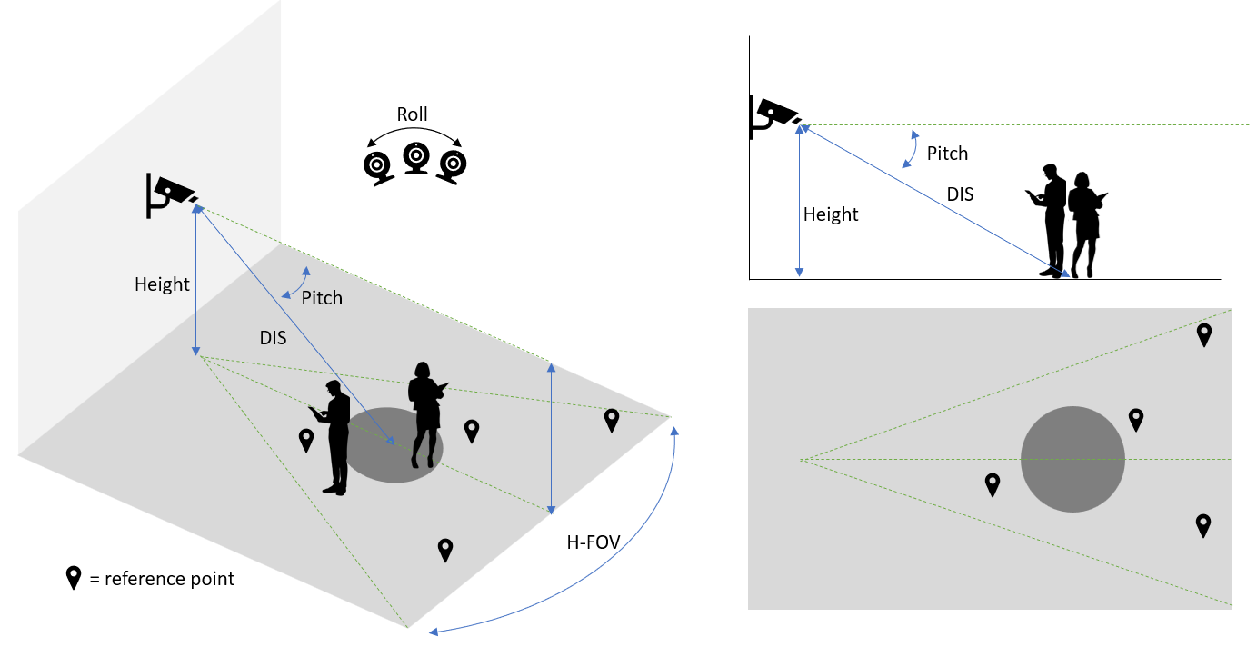
Pitch: the angle between the camera center line and the horizontal plane (the rotation around the side-to-side axis).
Height: The mounting height of the camera from the ground.
Roll: The camera rotation around the front-to-back axis.
H-FOV: Field of View, the extent of a camera’s range of observation.
DIS - Distance to center: The distance from the camera to the center of the area of detection.
Guideline#
Keep the camera’s Pitch between 45 and 15 degrees. The smaller the pitch is, the better the detection model can extract appearance features. The larger the pitch is, the more accurate the calibration can project detections on the plan map. Keeping the cameras’ Pitch within the recommended range helps on the overall performance of the reference applications.
Mount the camera 8 to 14ft above the ground. Mounting the camera within the recommended range makes it easier to cover the area of detection while keeping the camera’s Pitch within the recommended range.
Strive to keep the camera roll at 0 degrees. Do not mount sideways or upside-down. Larger roll angles will introduce more errors on estimating the location of detected people in the plan map.
The camera’s FOV (field of view) should be between 80 and 120 degrees.
Distance DIS should be no less than 12ft, and no more than 40ft. Ensure that the center of the area of interest is in the center of camera’s FOV.
The camera view should be linear. Any warping effect or distortion will introduce errors on estimating the location of detected people in the plan map.
There should be at least four reference points on the floor from the plan map identifiable in the camera view. The reference points are used to create projections from camera view onto the plan map and human errors in the selection of reference points will impact the accuracy of estimating the location of detected people in the plan map. Users need to be creative in selecting reference points and the reference points need to be as precise as possible. The reference points can be wall corners, a shelf foot, a corner of a pillar, markers (even temporary created markers), etc.
Each camera should look at a clear pathway, e.g., a lane between shelves in a retail store, to reduce occlusion as much as possible.
The above guidelines serve for the following purposes:
The occlusion on people to be detected should be as minimal as possible. (Most important)
The people to be detected should be present with large enough size in the camera view. Preferably the size is > 5000 pixels (~70x70).
The people to be detected should be observed more in a side angle rather than a top-down angle so that better appearance features can be extracted.
The foot location on the floor of the people to be detected should be clearly visible (So that we can estimate the location in the plan map).
Examples#
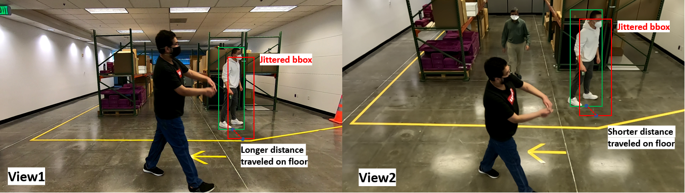
Consider the following two views as a comparison:
View1: Camera mounted at around 5ft high with a Pitch angle around zero degree.
View2: Camera mounted at around 12ft high with a Pitch angle around 30 degrees.
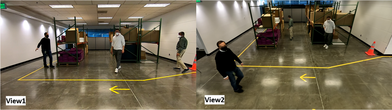
From the perspective of Metropolis reference applications, View2 is better than view1 for the following reasons:
In view1, there are more chances for occlusions between moving objects due to the low mounting height.
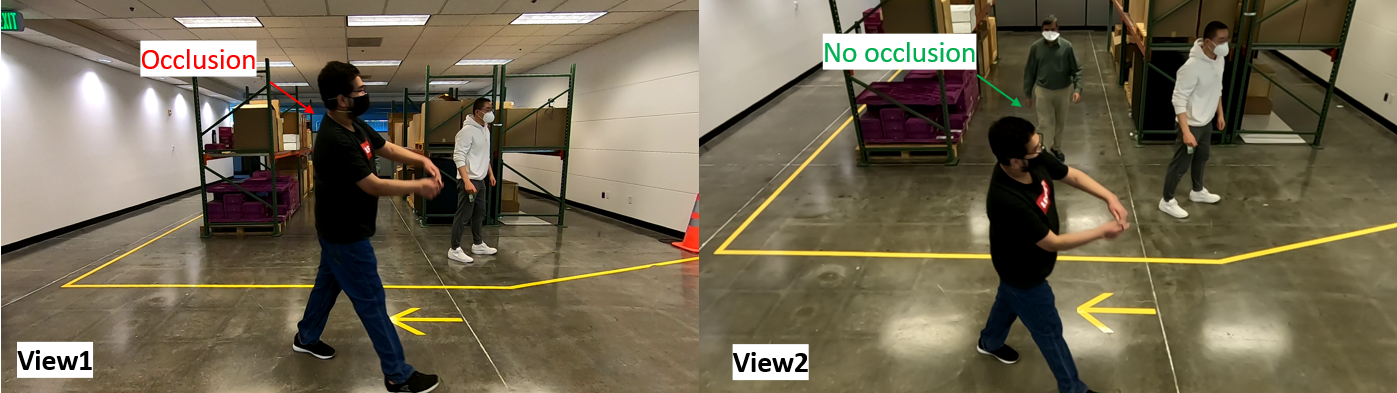
In view1, there are more chances for bad detection due to people partially present outside of the camera view. In the provided sample image below, the detected bounding box does not cover the foot, and the location of the detected person will be completely off in the plan map.
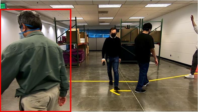
In view1, the location estimation in the plan map will have larger jitters than view2 due to its small Pitch angle.
Camera Selection#
We recommend using ONVIF compliant cameras for the best compatibility with the Metropolis platform. For a list of tested cameras, refer to Cameras Tested in VIOS.
Time drift may occur in ONVIF cameras, which can lead to synchronization issues between multiple cameras. To mitigate this, refer to Handling time drift in ONVIF cameras for best practices.
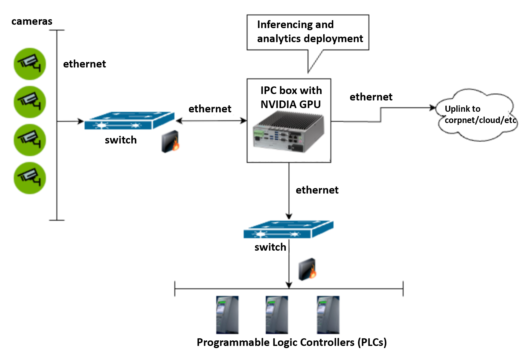
Camera Connection#
When connecting live cameras to the Metropolis analytics system for an on-prim deployment where latency is one of the primary concerns, it is recommended to connect all cameras to the same switch and then connect to the system where the analytics system is deployed on through local ethernet. Thus connection delayout will best ensure the time synthronization across all cameras and minizie the end-to-end latency. A reference connection diagram is shown below: