Camera Calibration Toolkit#
Overview#
The Metropolis Camera Calibration Toolkit helps you set up and calibrate cameras for use with Metropolis Apps and Microservices. This React/Python web application streamlines onboarding, calibration, and export of camera configurations for NVIDIA developers.
Key Features: - Onboard and configure cameras - Calibrate cameras for accurate mapping to real-world coordinates - Define Regions of Interest (ROIs) and virtual tripwires - Validate calibration results - Export calibration data for downstream applications
Note
Only 2D camera calibration is supported (using a 3x3 homography matrix).
Cameras with significant lens distortion should be rectified before calibration, as the toolkit assumes a linear (undistorted) camera view.
Through the provided tooling, essentially it helps to find the anchor point pairs between the 2D pixel domain and the 2D floor plan map and further to provide the 2D-to-2D perspective transformation matrix (3-by-3 homography matrix).
Prerequisites#
Hardware Requirements#
8 GB system RAM
2 core CPU
50 GB of HDD space
Recommended
16 GB system RAM
4 core CPU
100 GB of SSD space
Software Requirements#
OS Independent – Recommended: Ubuntu 22.04 LTS
Browser - Recommended: Google Chrome
Google Maps JavaScript API Key (for GIS Calibration)
Create an account with Google if you don’t have one already, and enable Google Maps Javascript API.
OpenStreetMaps Link (for GIS Calibration)
Locate the appropriate Open Street Map Link from here.
We will need this in generating the Intersection Road links. Try to find the map most local to the city you are calibrating, as this will quicken the computation.
Installation Requirements#
RTSP links to cameras, or screenshot views of cameras
Building map or floor plan (top-down 2D schematic drawing of the location covered by cameras)
Installation#
Pull the docker from NGC:
docker pull nvcr.io/nvidia/vss-core/calibration:3.1.0
Create a directory to store your data:
mkdir <path/to/dir>/data
Run the docker container using host’s port 8003, and mounting the aforementioned directory as your data folder.
docker run -p 8003:8003 -v <path to data dir>/data:/calibration/server/data/ -it nvcr.io/nvidia/vss-core/calibration:3.1.0 deploy.sh 8003
Note
Run the container on your local system or use SSH tunneling if accessing remotely. Otherwise, you may not be able to connect to the web UI.
Navigate to http://localhost-or-remote-IP:8003, where the application will be live. In K8s deployment, navigate to http://localhost-or-remote-IP:31080/calibration.
Project Setup#
This section explains how to set up projects and configurations for Metropolis Apps or Microservices.
Project Types: - GIS Calibration: For GIS-based applications - Cartesian Calibration: For single-camera, approximate cartesian calibration - Multi-Camera Tracking Calibration: For calibrating multiple cameras on a single floor plan - Image Calibration: For ROI/tripwire calibration on images only
After selecting a project type, enter the project to begin calibration.
Note
Use Cartesian Calibration for Occupancy Analytics (OA) reference app.
Use Multi-Camera Tracking Calibration for Multi-Camera Tracking reference app.
Multi-Camera Tracking uses a floor plan; Cartesian does not.
When you do have a floor plan map, reference points are selected from camera view and plan map, which is straight forward. But when you don’t have plan map, you would need to imagine a top-down view as the floor plan while selecting the reference points from camera view. So (for advanced users) if you have a floor plan for your OA app, you can use Multi-Camera Tracking Calibration (aka calibration with floor plan) for your OA app.
You can import projects exported from previous deployments (version 1.1 or later):
Import Project#
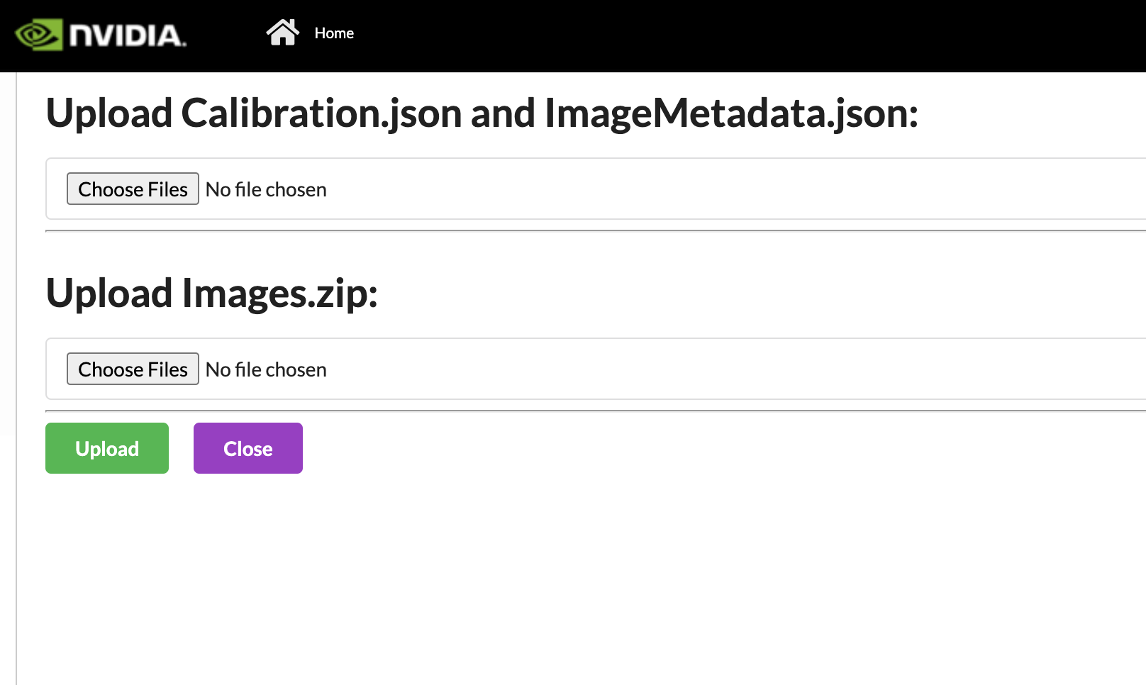
We can also can import projects that were exported from previous deployments (1.1 onwards). First, upload the calibration.json and the imageMetadata.json. The naming must match to be uploaded. Then we will upload the Images.zip which also comes from the export. It may take some time for the images upload to happen. Please wait for the green Zip file uploaded before pressing the Upload button. If the project already exists, the naming will be changed to reflect that it is unique. Also, if a project named “_” is created as a temporary project and does not auto delete, it will block all new imports. Please ensure no project is named “_”, before importing.
Sensor Discovery#
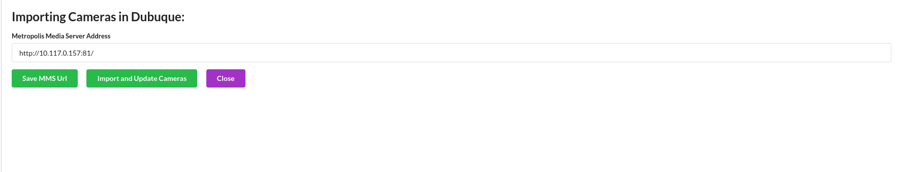
The first step is to add cameras. If you have set up VST, you can import the available sensors and propagate some of the sensors details available. If possible, it will also try and take screenshots of the current camera view. This will save time from importing it manually. It may take some time for the sensors to be imported.
The URL templates are shown below:
For VMS:
Standalone:
http://<VST_IP>:30000/K8s Deployment Non Hosted:
http://<HOST_IP>:31080/vms/K8s Deployment Hosted:
http://vms-vms-svc:30000/
For NVSTREAMER:
Standalone:
http://<NVSTREAMER_IP>:31000/K8s Deployment Non Hosted:
http://<HOST_IP>:31080/nvstreamer/K8s Deployment Hosted”
http://nvstreamer-nvstreamer-svc:31000/
Otherwise, create new sensors in the Setup sensor page.
Sensor Configuration#
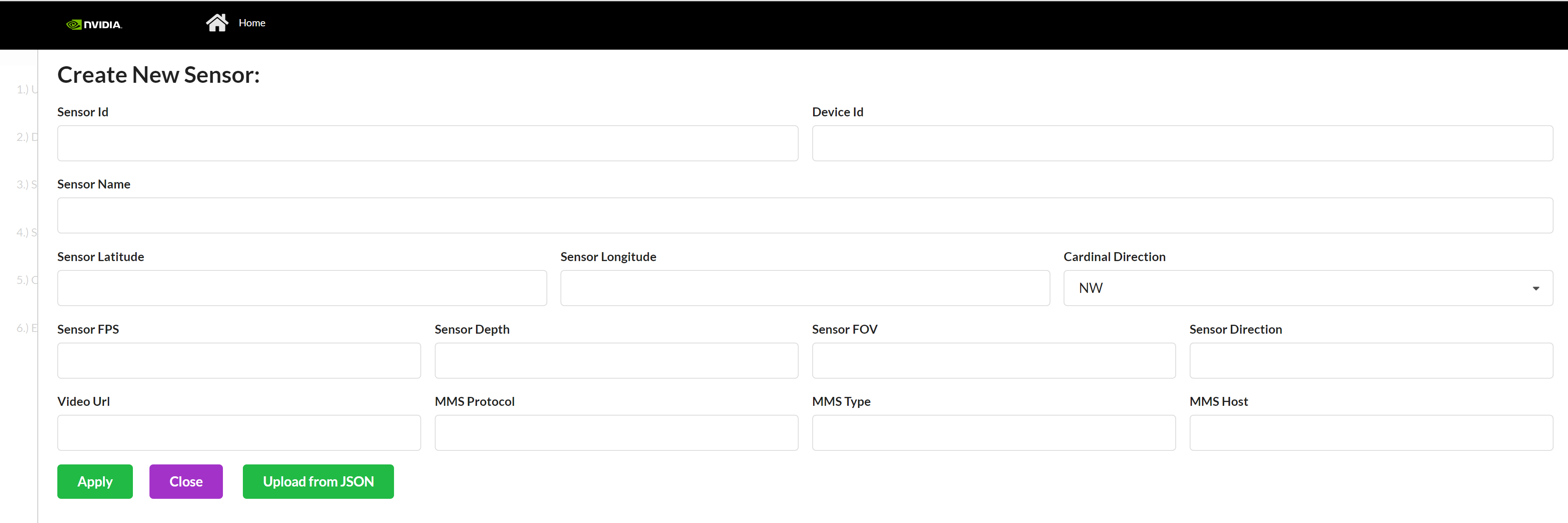
A sensor consists of the metadata that we will be calibrating. These are the common cameras:
Sensor Id* - Sensor ID is the unique name of the sensor, which will be used throughout Metropolis microservices.
Camera Name* - A name that can be used to find the camera in Media Server or ONVIF id
Camera Latitude* - Latitude of Sensor. Range (-180, 180) but cannot be 0. This field is mainly used in Project Type - GIS (for ITS app), and for other project types the value here doesn’t matter, you may input 1 as the value.
Camera Longitude* - Longitude of Sensor. Range (-85, 85) but cannot be 0. This field is mainly used in Project Type - GIS (for ITS app), and for other project types the value here doesn’t matter, you may input 1 as the value.
Cardinal Direction - Direction of the cars, the Camera’s Field of View sees. For example, if a camera is facing south, the camera’s Field of View is North Bound or NB. This field is mainly used in Project Type - GIS (for ITS app), and for other project types the value here doesn’t matter.
FPS* - Integer referring to Sensor’s Frame per second. This field is mainly used in Project Type - GIS (for ITS app), and for other project types the value here doesn’t matter, please input 0 as the value.
Direction - Integer between 0 and 360, measured in degrees, with 0 as North. This field is mainly used in Project Type - GIS (for ITS app), and for other project types the value here doesn’t matter, please input 0 as the value.
Depth* - Integer referring to Sensor’s Depth. This field is mainly used in Project Type - GIS (for ITS app), and for other project types the value here doesn’t matter, please input 0 as the value.
FOV* - Angle of the Sensor. This field is mainly used in Project Type - GIS (for ITS app), and for other project types the value here doesn’t matter, please input 0 as the value.
Video URL* - hls or webRTC URL used by Metropolis microservice UI. This field is mainly used in Project Type - GIS (for ITS app), and for other project types the value here doesn’t matter, you may input 0 as the value.
MMS Protocol* - 2 options “
webrtc” or “hls”. Use the exact spelling. This field is mainly used in Project Type - GIS (for ITS app), and for other project types the value here doesn’t matter, you may input 0 as the value.MMS type* - 2 options “
nvMms” if you are using MMS, or “wowza”. Use this exact spelling. This field is mainly used in Project Type - GIS (for ITS app), and for other project types the value here doesn’t matter, you may input 1 as the value.MMS Host* - http URL that points to the Media Server. Be sure to include “
http://” and if you are using MMS, include port 81. This field is mainly used in Project Type - GIS (for ITS app), and for other project types the value here doesn’t matter, you may input “http://” as the value.Corridor* - Corridor that the camera belongs to. This field is mainly used in Project Type - GIS (for ITS app), and for other project types the value here doesn’t matter, you can keep it empty.
Intersection* - Intersection that the camera belongs to. This field is mainly used in Project Type - GIS (for ITS app), and for other project types the value here doesn’t matter, you can keep it empty.
*required
Project Type - GIS#
Camera calibration in this application refers to obtaining a homography matrix for projecting points from camera image coordinates, (i.e. pixel coordinates), to the global satellite space (i.e. latitude/longitude co-ordinates). Calibration is required because objects detected and located in the image do not provide sufficient information for data analysis.
Consider the case of a car driving along the road. A car can be detected and tracked through a series of video frames, but without calibration, its speed could only be tracked at a pixel scale. Instead, we want to transform those detected pixel locations to satellite coordinates, to be able to track the speed of the car in kilometers or miles per hour.
To calibrate, we will draw one polygon in the image view marking static landmark features and another polygon in the satellite view that matches the same landmark features as in the image view. The idea is that these landmarks are an example of how the same object is located in image coordinates and global satellite coordinates. The more accurate landmark pairs, the better the homography matrix will be able to be calculated.
Group Configuration#
Intersection#
Overview
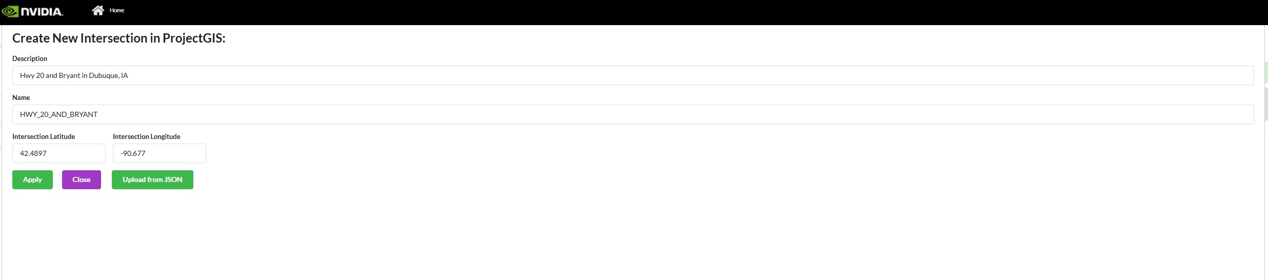
Intersection is a crossing of two roads. In this, we try to group cameras that cover the same two roads. This grouping allows us to configure “Intersection View” within the UI.
Properties
Name (Name of Intersection) - often this is the common Major Road and Minor roads of a group of cameras
Description
Intersection Latitude - Latitude of center of Intersection
Intersection Longitude - Longitude of center of Intersection
Corridor#
Overview
A corridor is a group of cameras that might fall under a large artery, such as a highway. For a broader definition, FRC (federal road class) level 1-3 can be called a corridor. (Total 6 levels - Interstate, Other Freeways & Expressways, Other Principal Arterials, Minor Arterials, Major and Minor Collectors, Local Roads. (source). This grouping allows us to configure “Corridor View” within the UI.
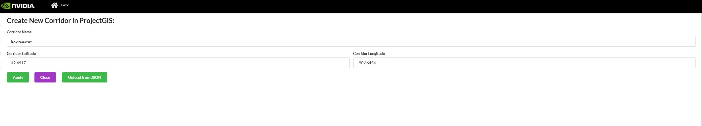
Properties
Name - Name of Corridor – often this is the common Major road among intersections and their cameras
Corridor Longitude - Latitude of the center of Corridor
Corridor Latitude - Longitude of the center of Corridor
Drawing Guideline#
Drawing polygons and polylines in both the image space and map space/floor plan is a key feature in this app. The features for drawing polygons and polylines are essentially the same, the only difference being if the first and last points are connected. We will cover the instructions to draw both polygons and polylines below.
Important: The best practice is to start drawing from the bottom left of the image/map, and to add points in a counter-clockwise fashion.
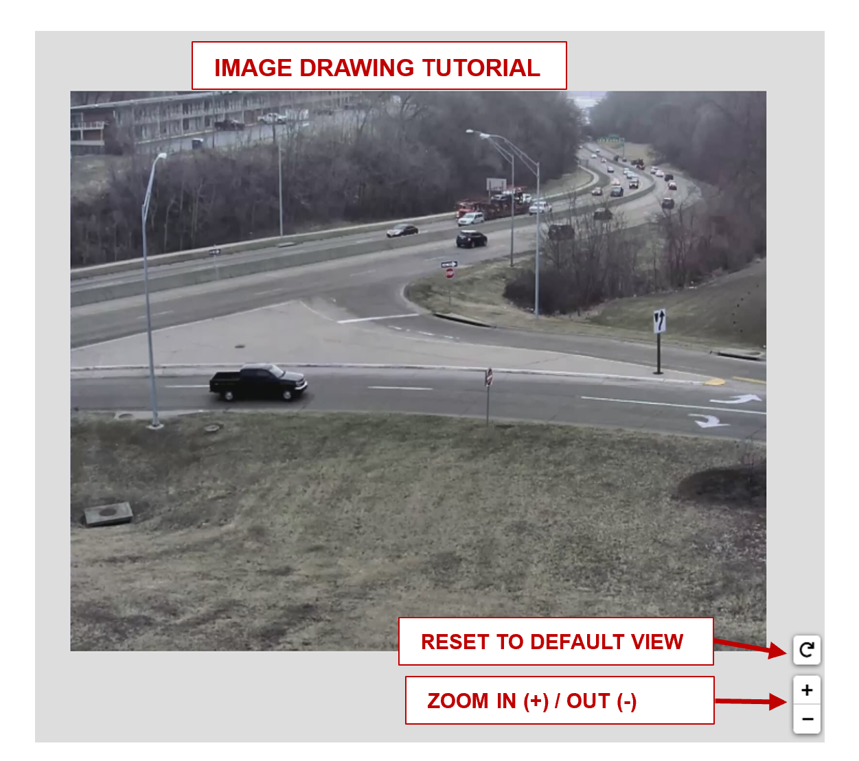
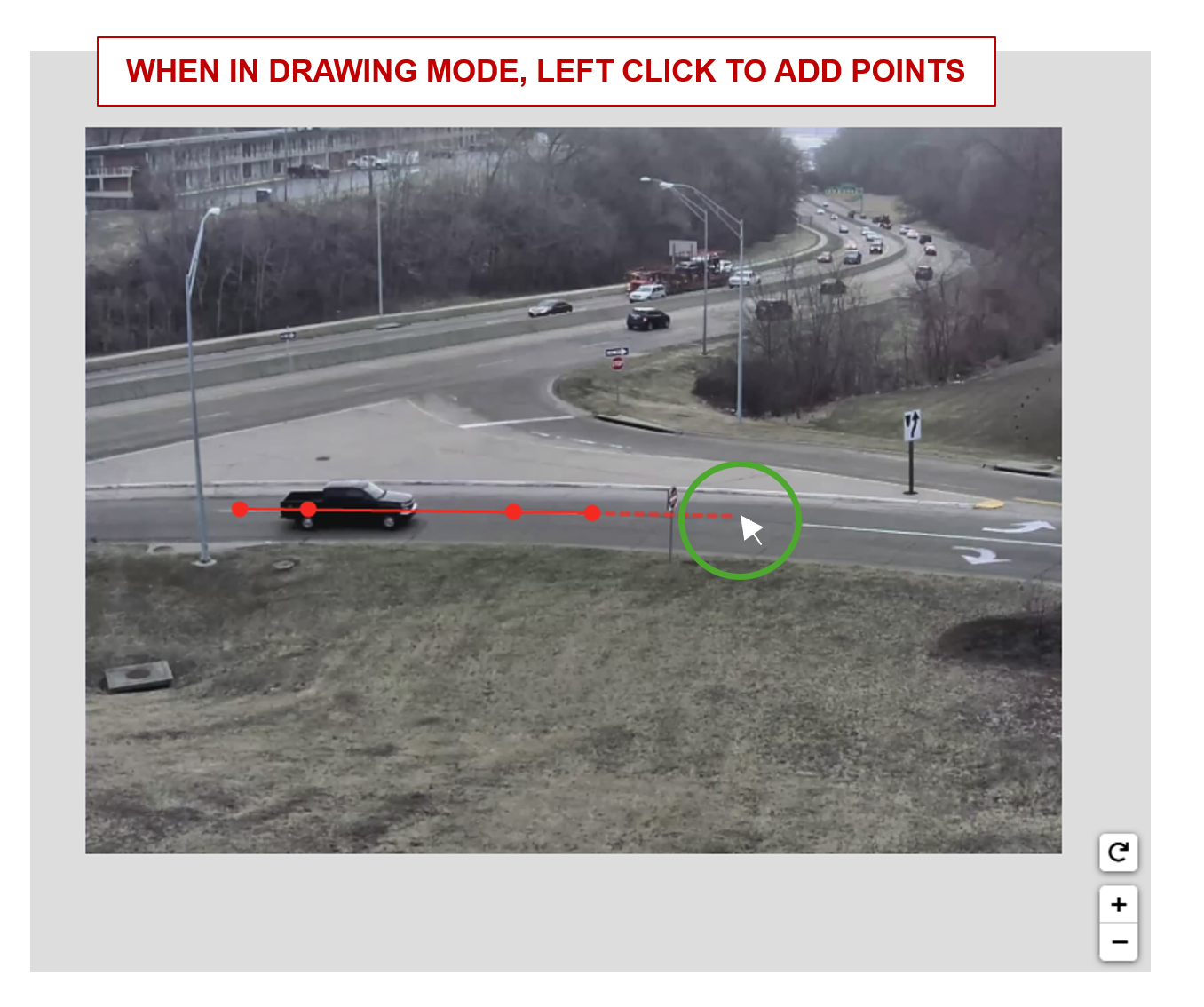
Image Drawing Guideline#
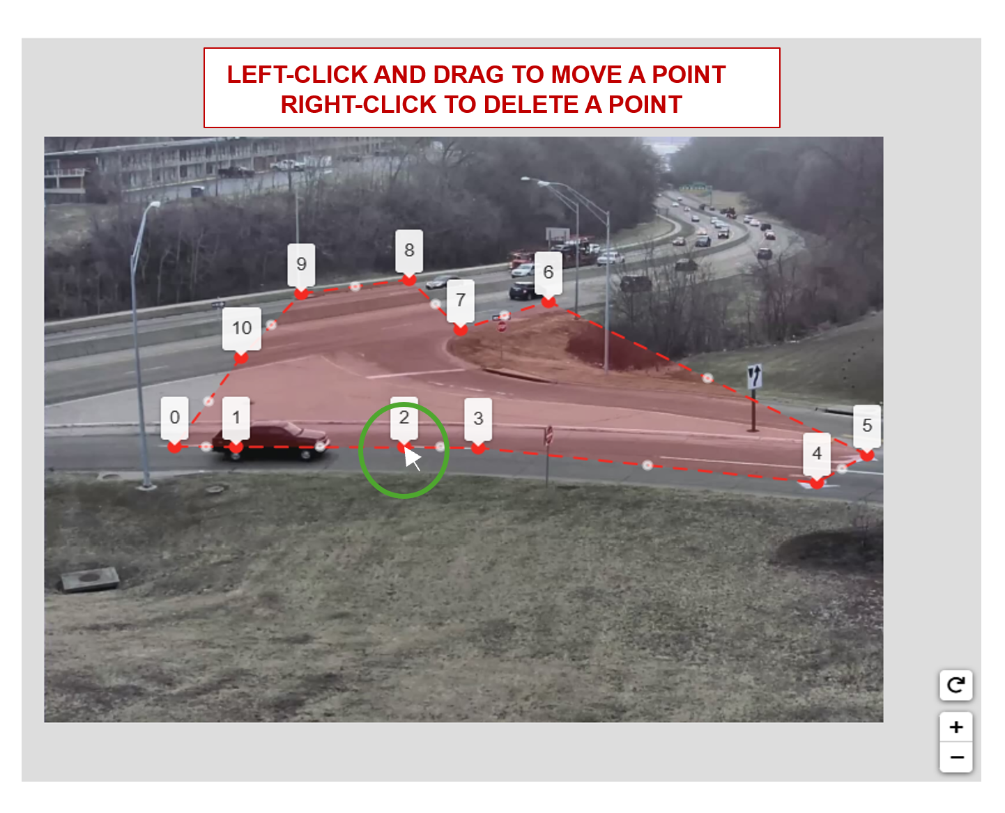
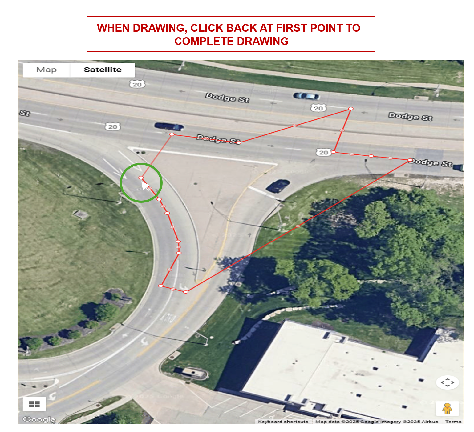
The image drawing container has pan and zoom capabilities. When in a drawing mode, left click on the image to draw and add points.
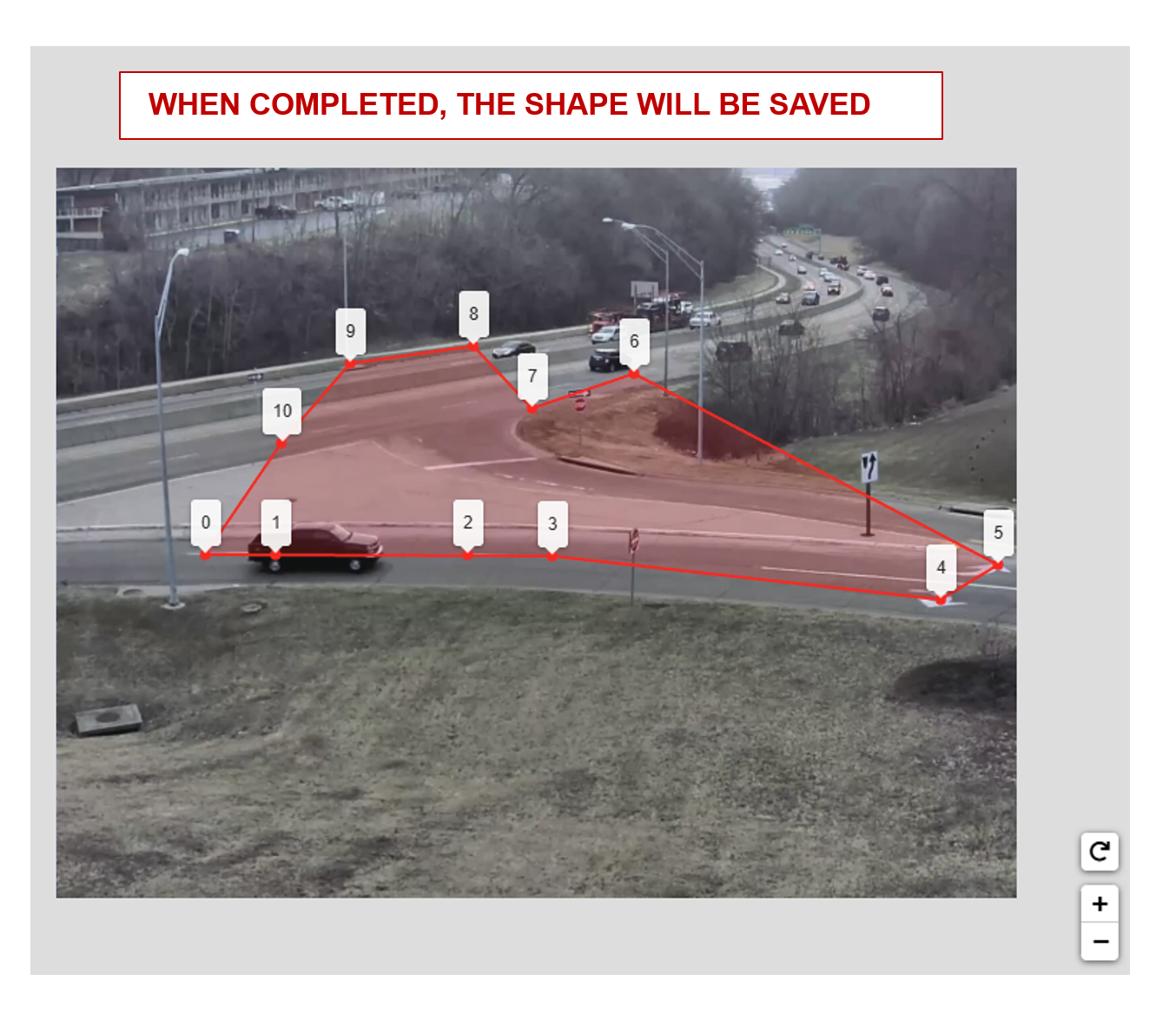
A polygon can be completed using either option below. A polyline can be completed using the endpoint option only.
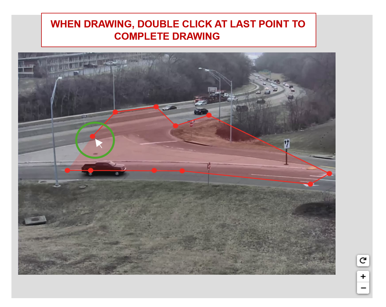
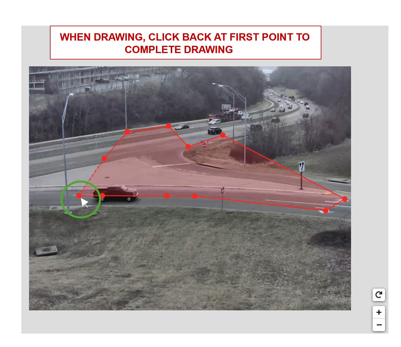
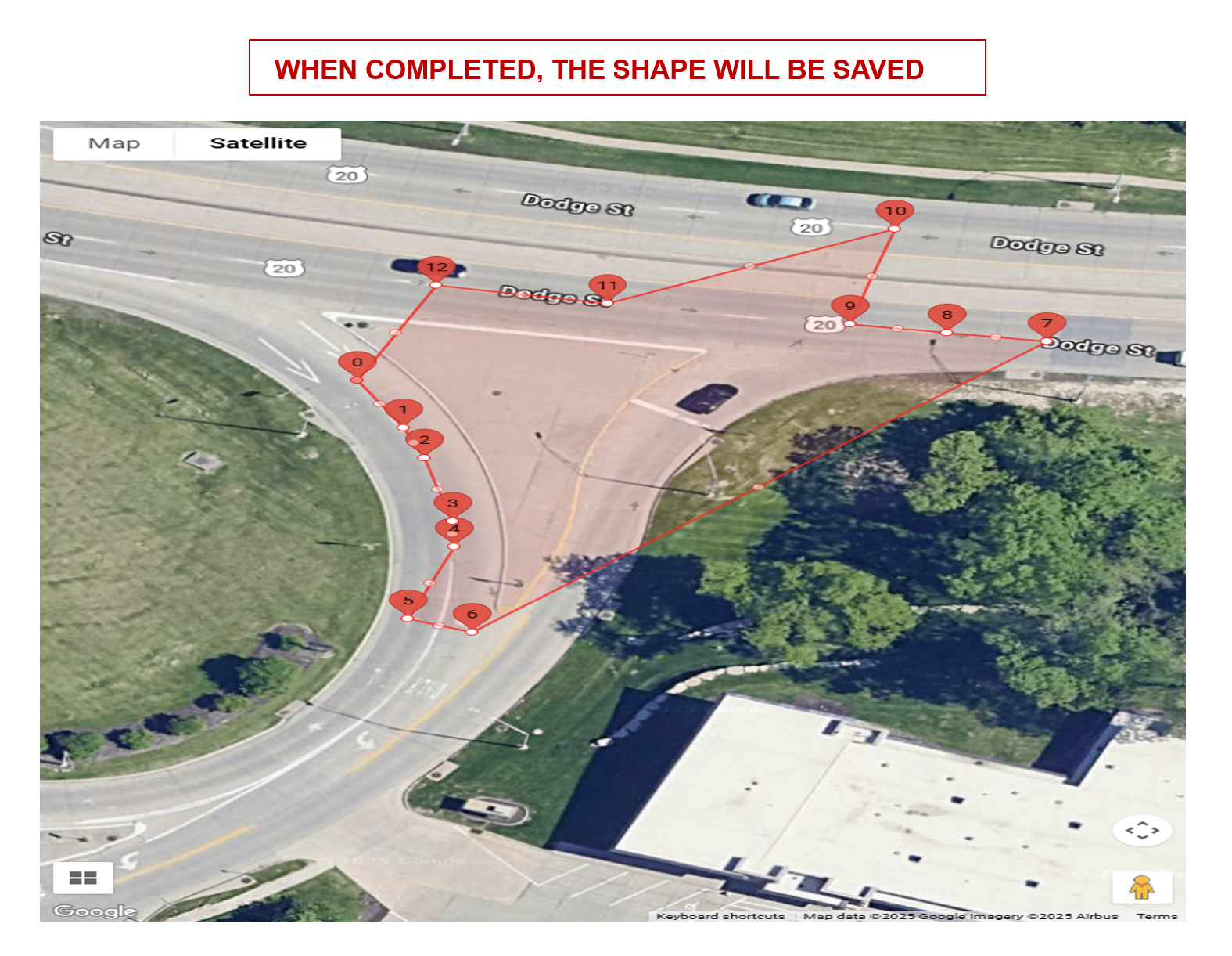
The shape will be saved upon completion. You can then click the shape to enable the edit mode.
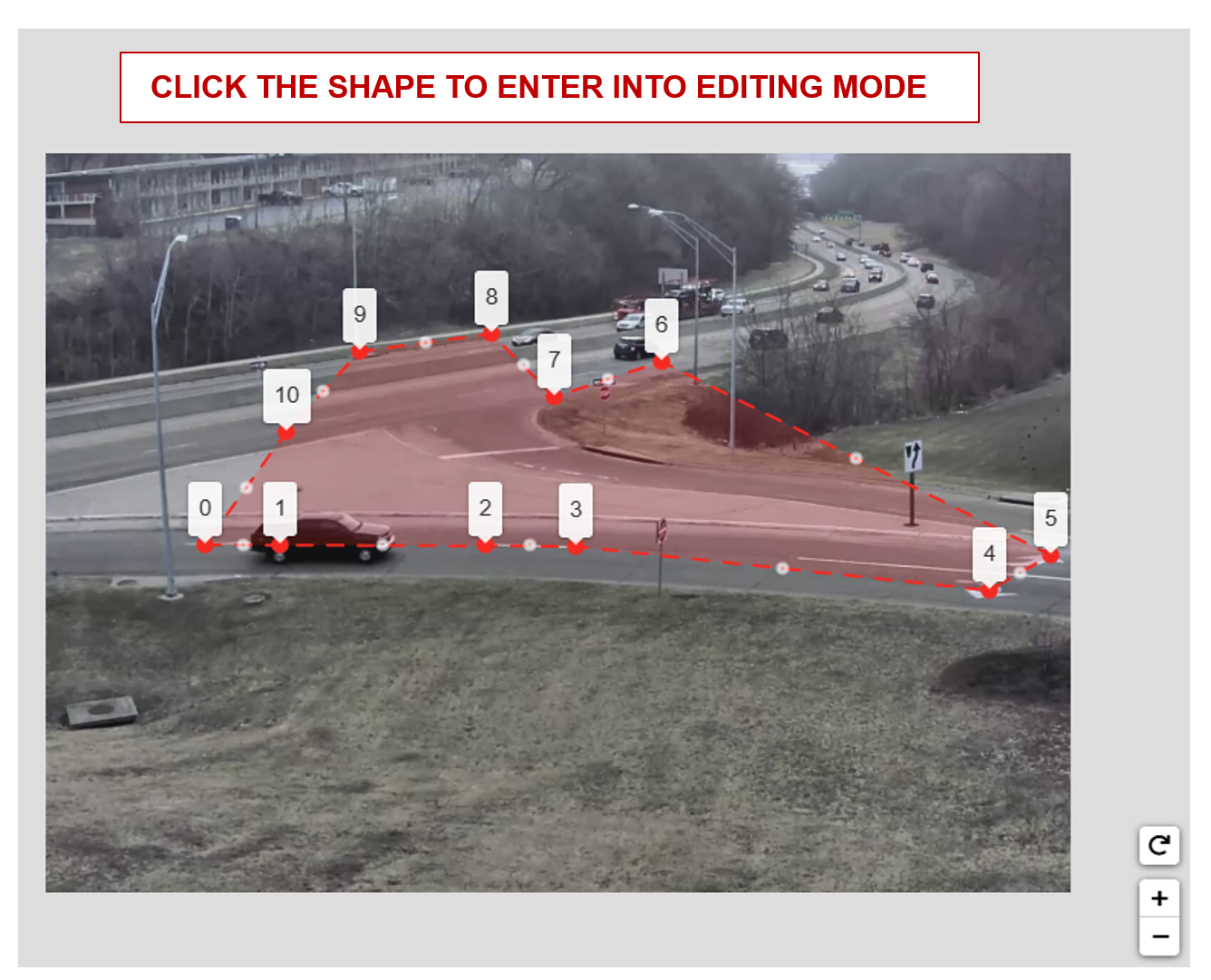
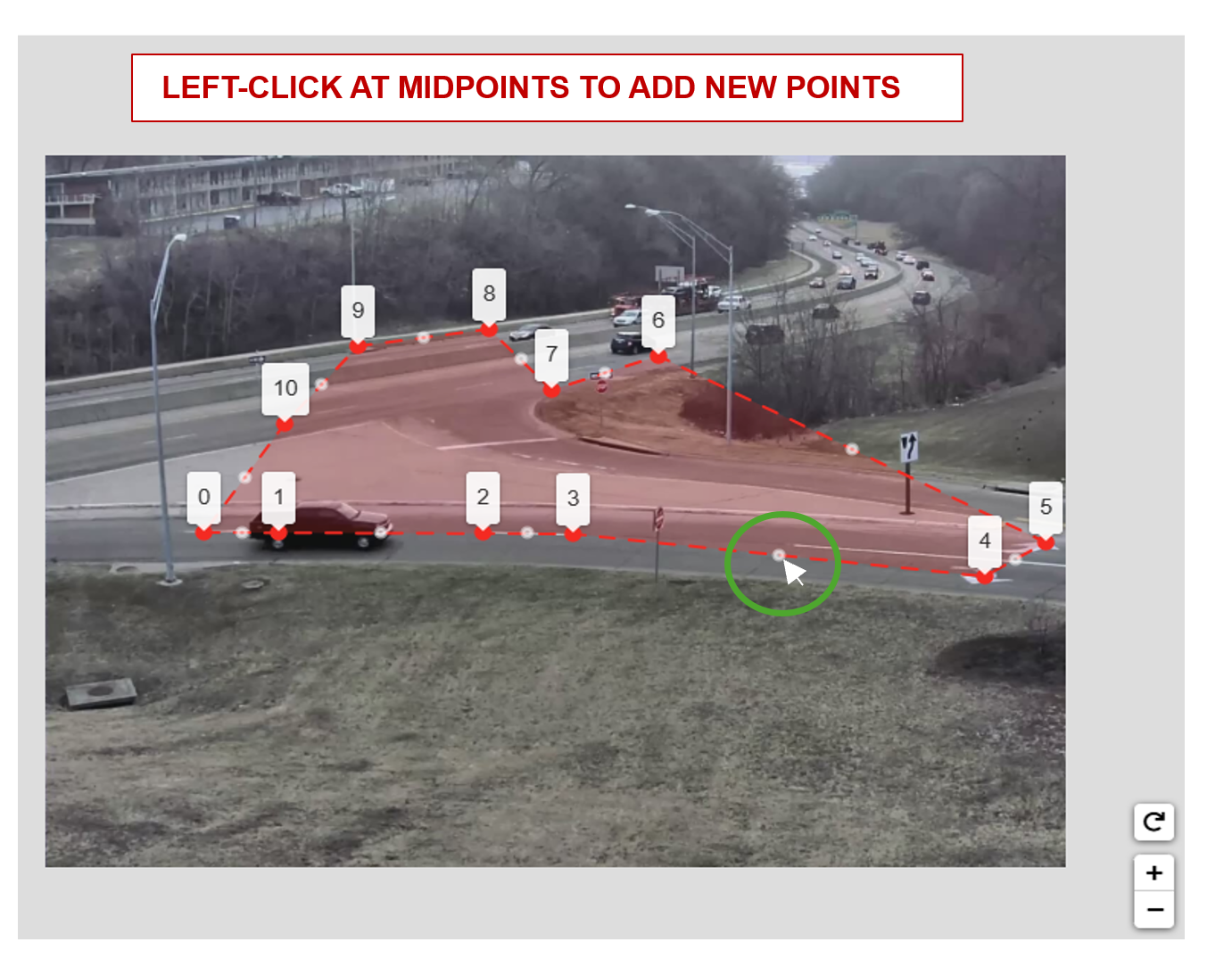
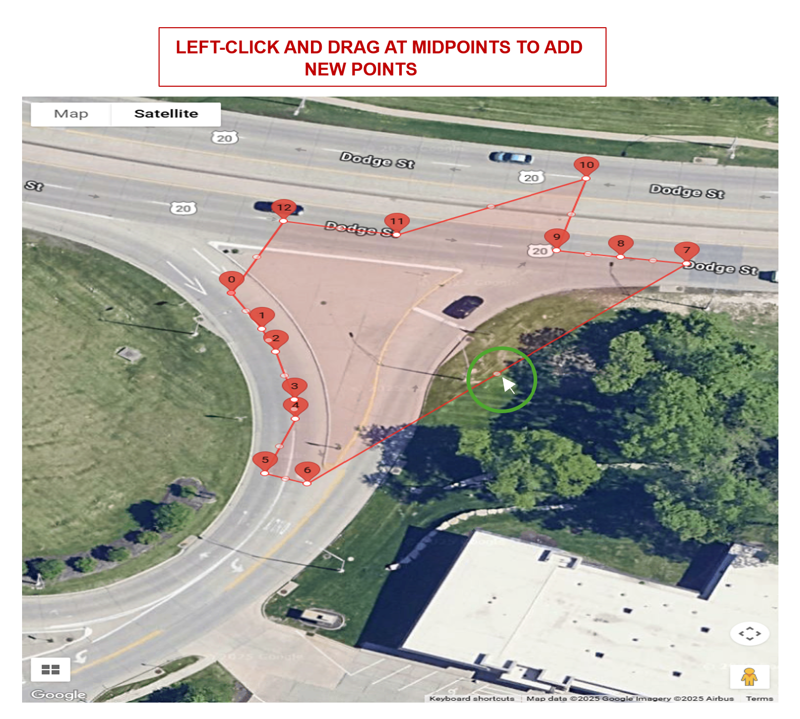
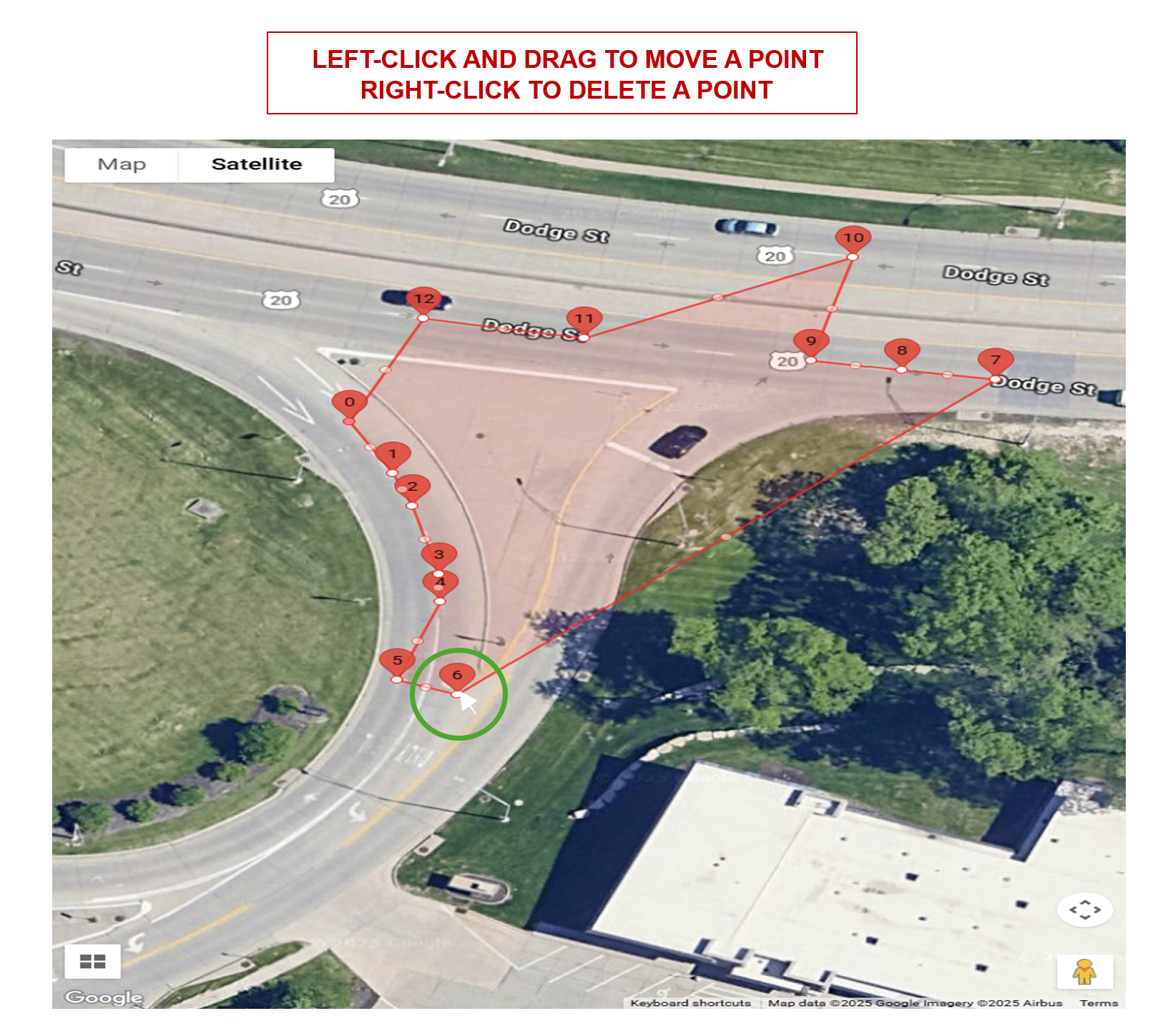
Polygons and polylines have the same capabilities of adding, moving, and deleting points.
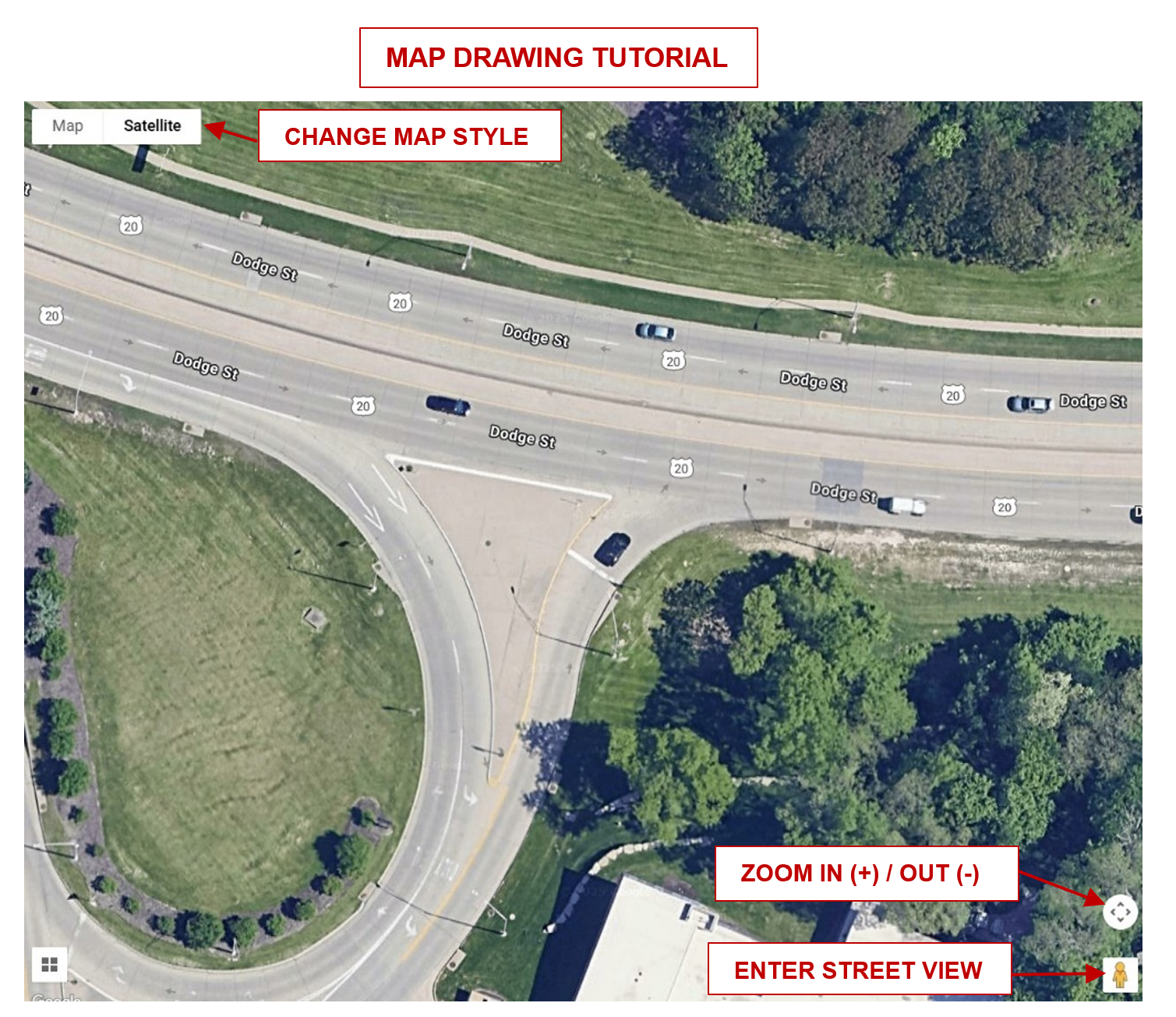
Satellite Map Drawing Guideline#
The map drawing container has pan and zoom capabilities. When in drawing mode, left click on the map to draw and add points.
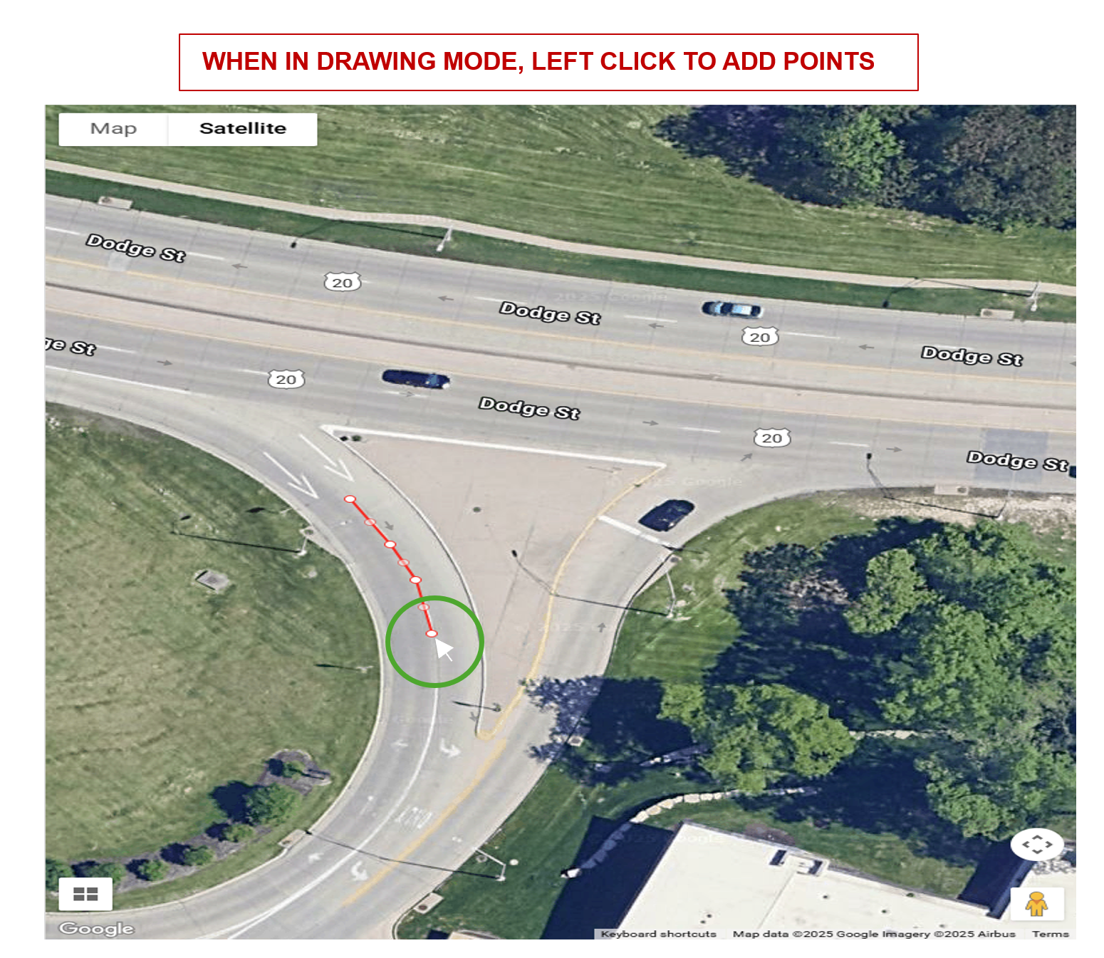
A polygon can be completed using either option below.A polyline can be completed using the endpoint option only.
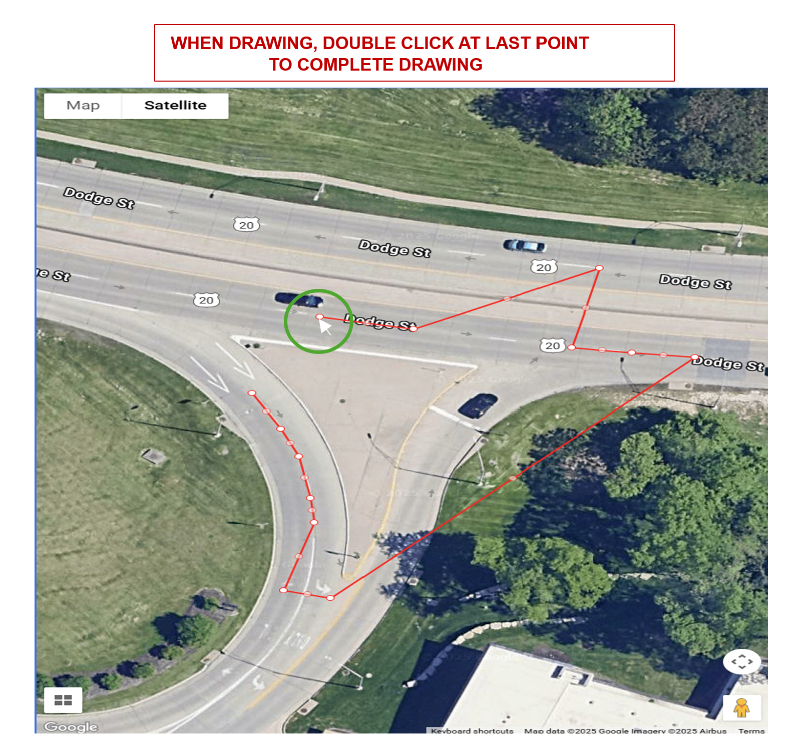
The shape will be saved upon completion. The user can edit at anytime and does not need to click to enter edit mode.
Polygons and polylines have the same capabilities of adding, moving and deleting points.
How To Calibrate#
Load the Camera Calibration Tool
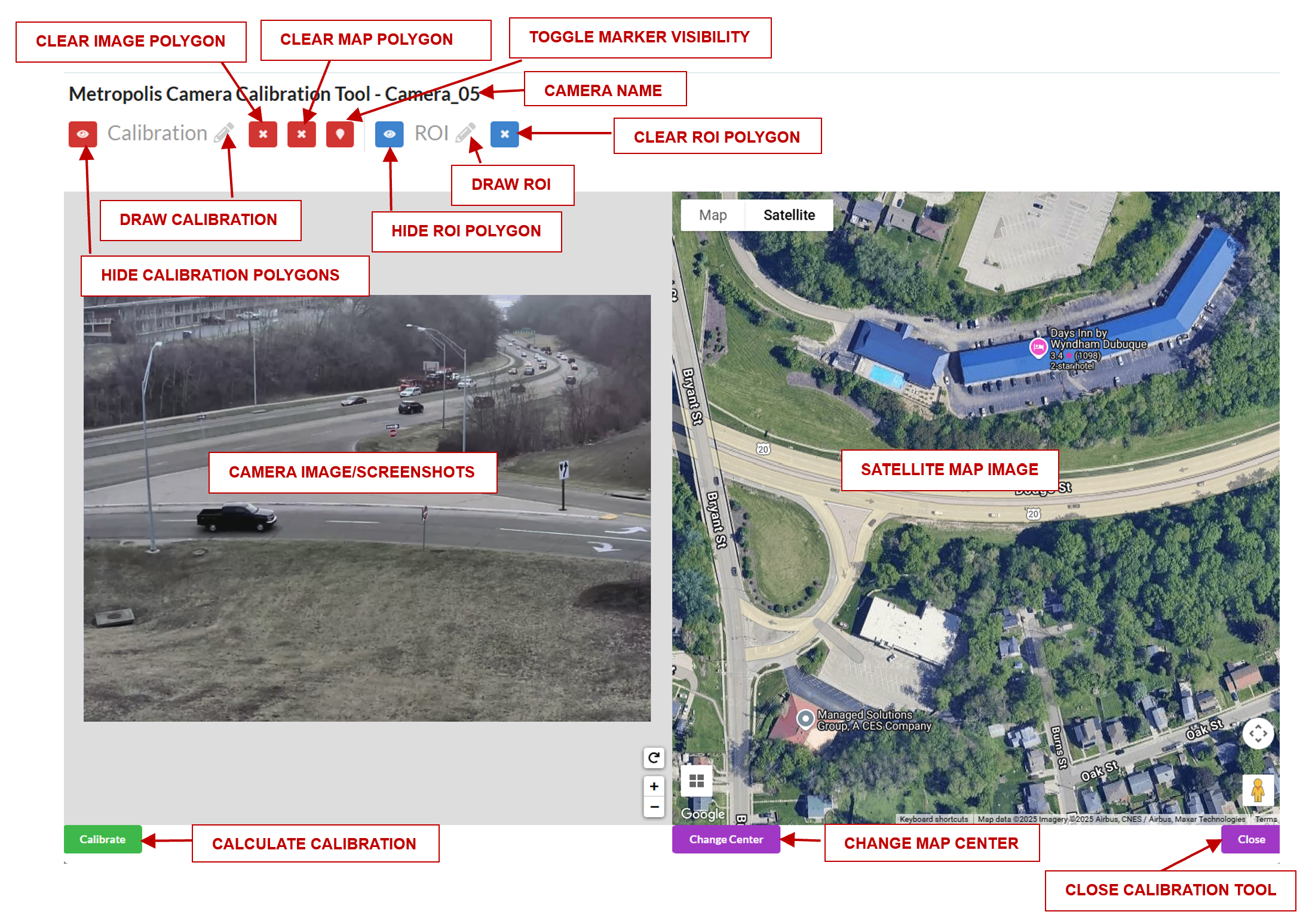
Draw a polygon of at least 8 landmark features that can be seen in both the image and the satellite view.
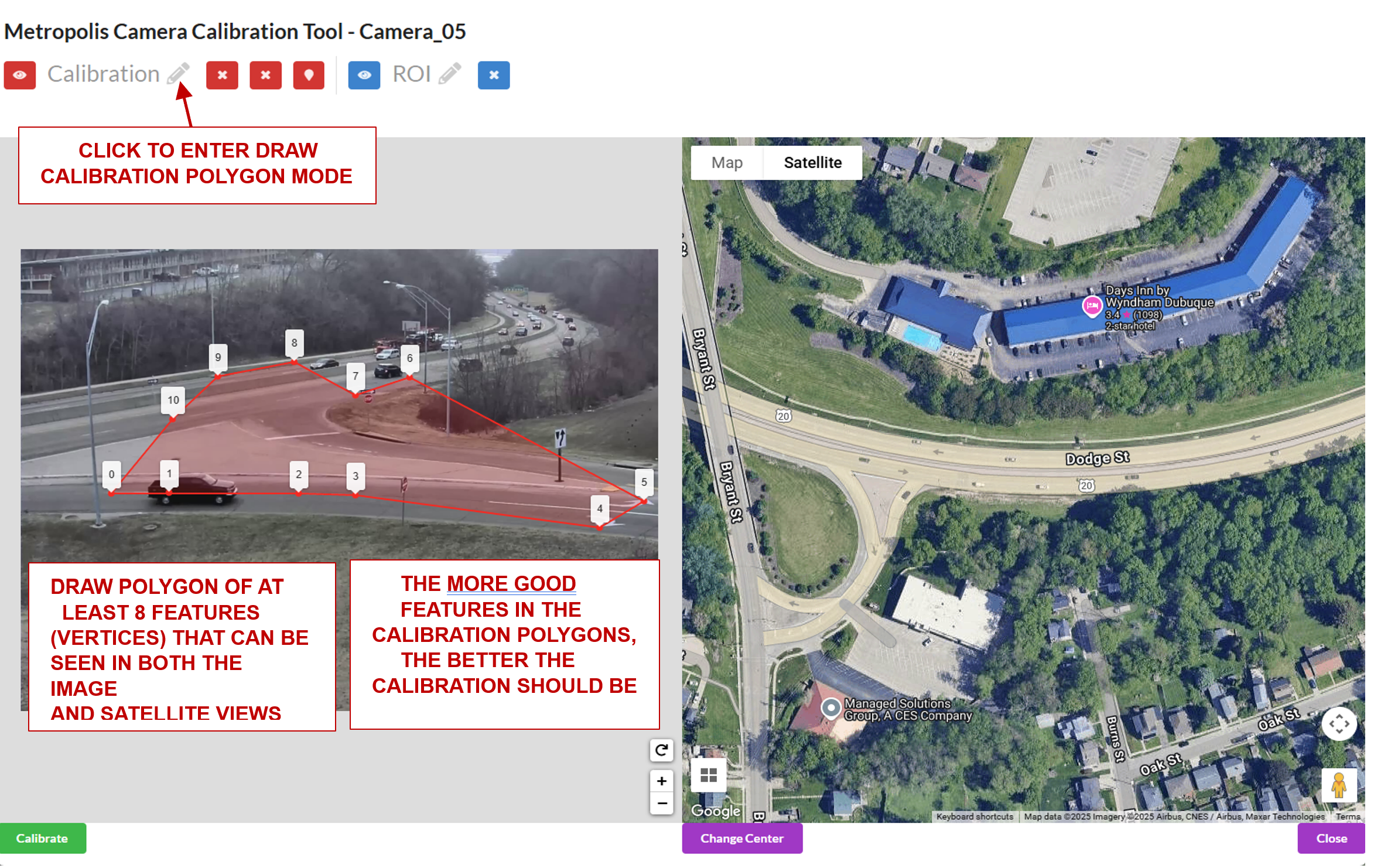
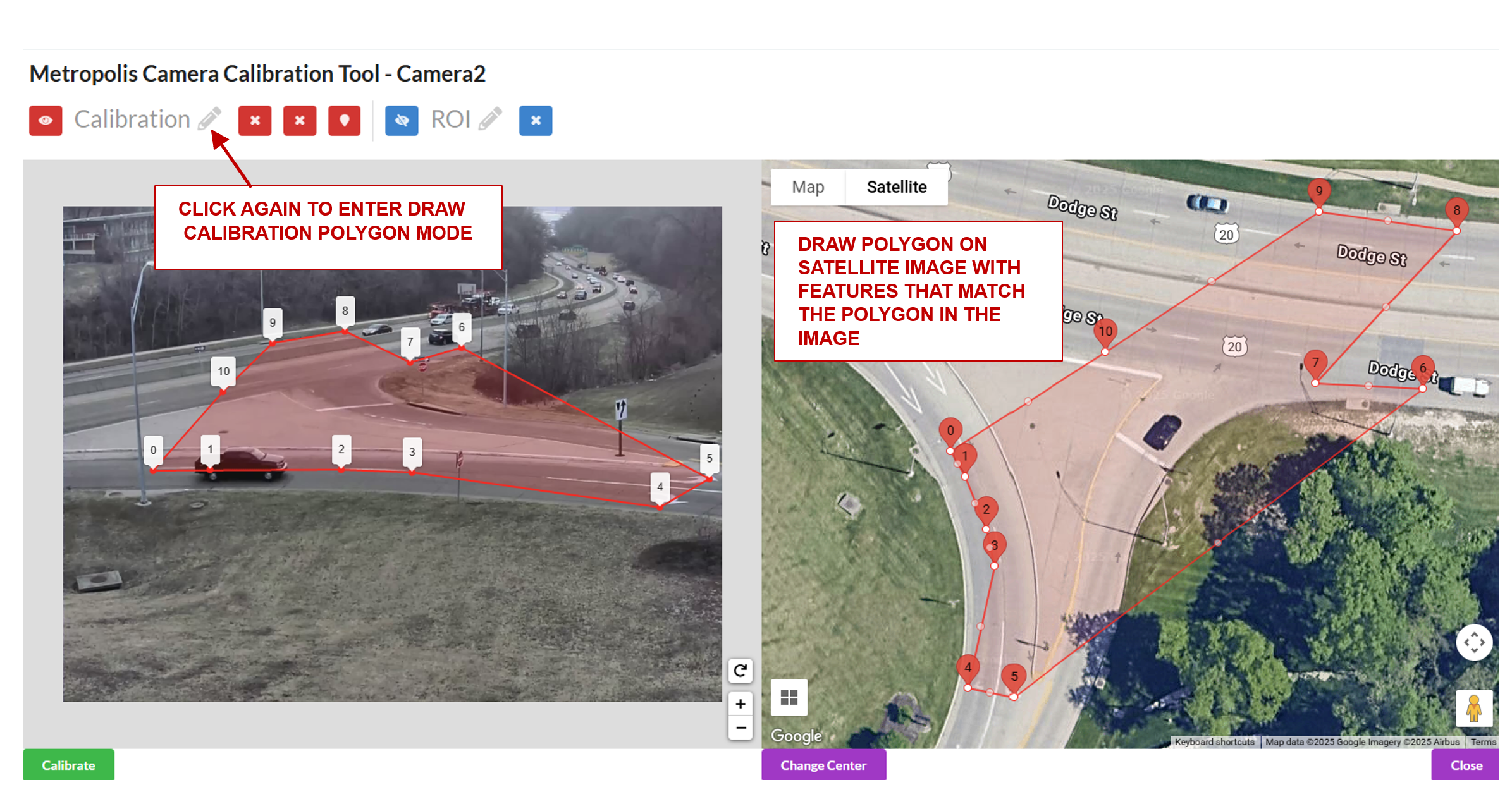
Draw a polygon on the satellite map with landmark features that match the polygon in the image.
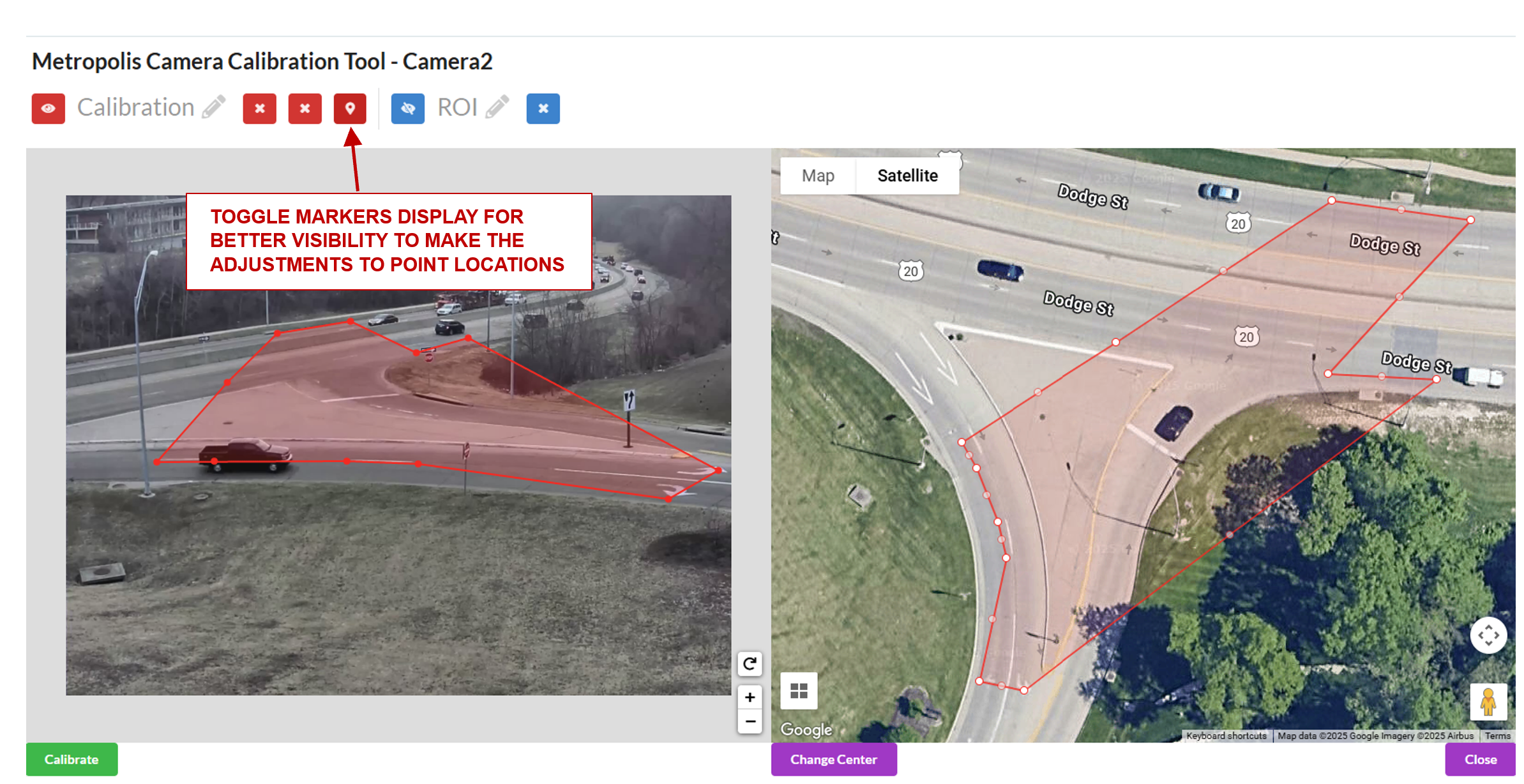
Use the toggle markers button for better visibility on the exact location of a point.
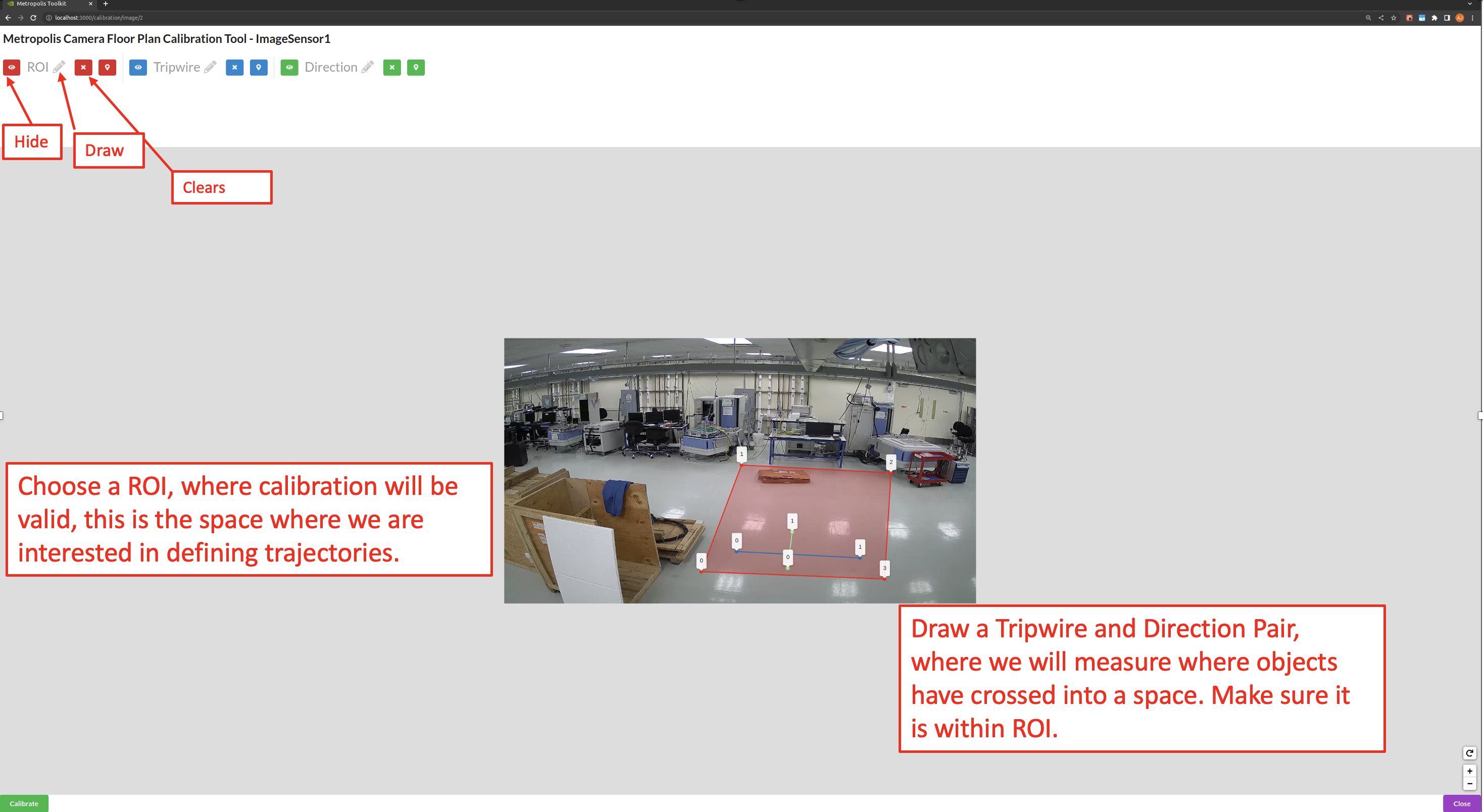
Draw the Region of Interest (ROI), which represents the area for which the calibration is intended to be valid. This does not necessarily have to be the sensor’s entire Field of View. Typically the calibration holds up to 200m away from the camera.
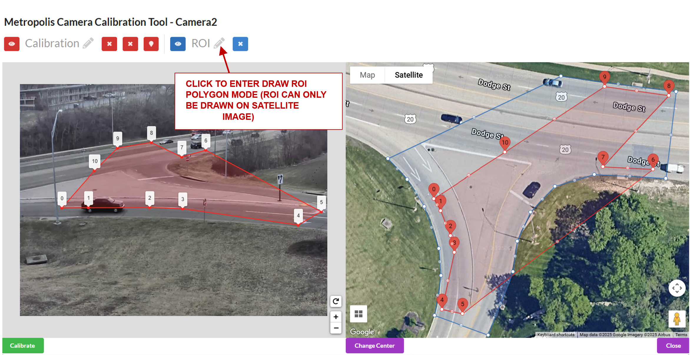
Notes on the Region of Interest (ROI): The homography matrix from the calibration relies on the assumption that the road is flat, and so the calibration is expected to produce erroneous results in the sky, on grassy hills, in trees, etc. Therefore, the ROI should cover the parts of the road that the camera can see, so the end application knows to ignore points outside this region. This helps prevent errors and improve performance. The ROI can be further adjusted at the Camera Validation step as the user will learn more about how well the calibration works in certain areas of the image.
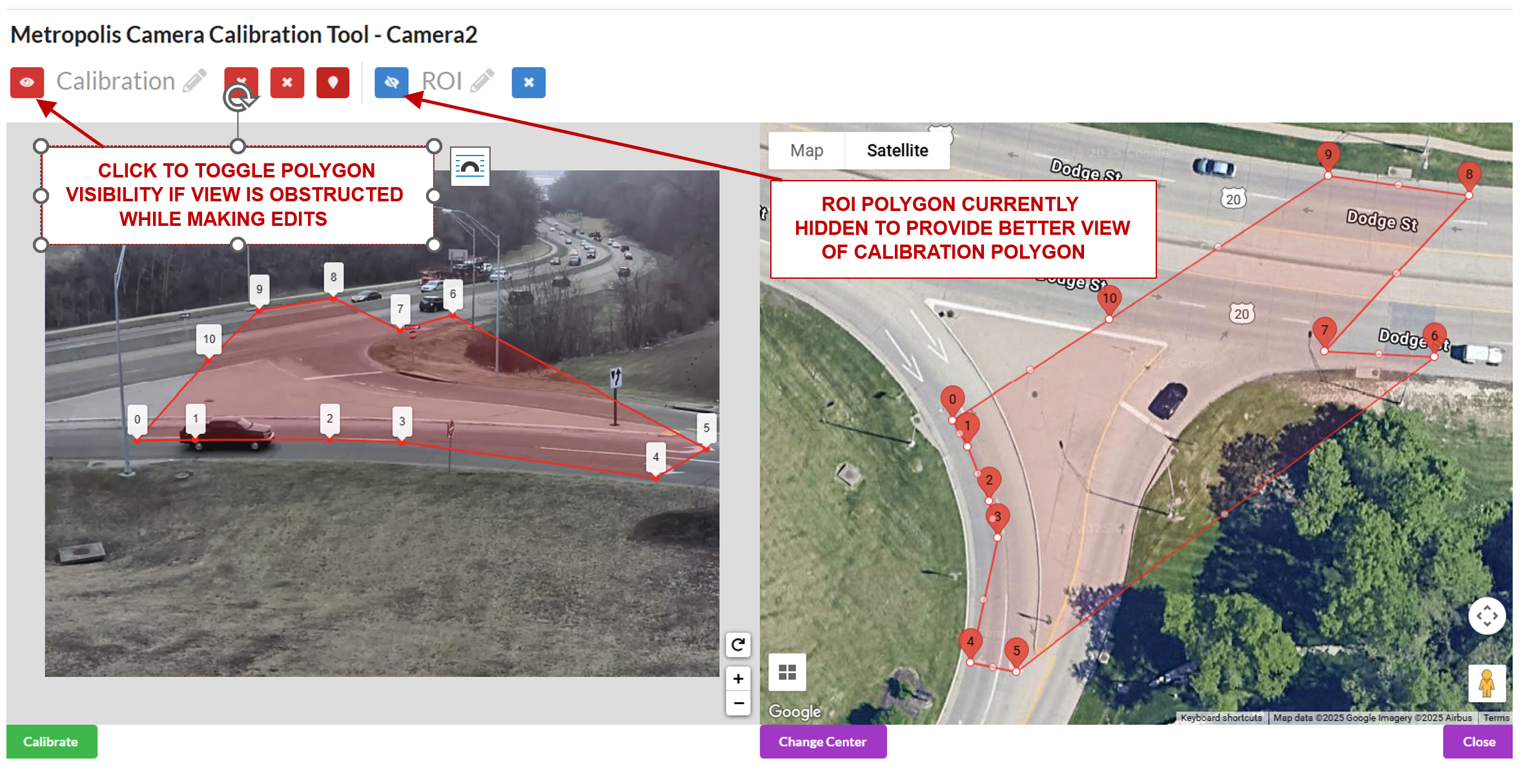
Toggle the visibility of either the calibration or ROI polygons for better visibility if required.
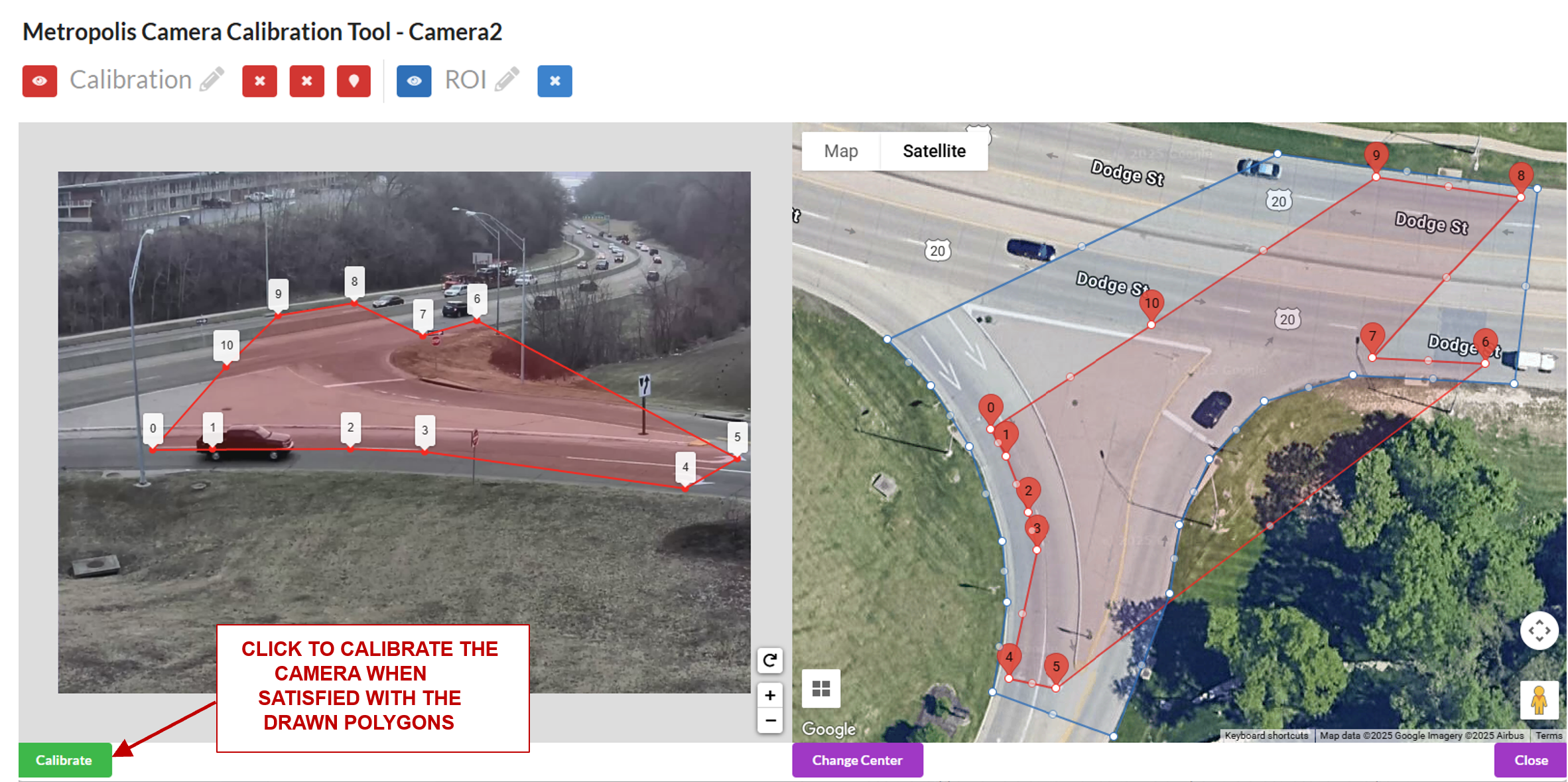
Click the Calibrate button to calculate the homography matrix.
Review the reprojection errors of the points. Click edit to go back and adjust points, or Accept Calibration to accept the homography matrix.
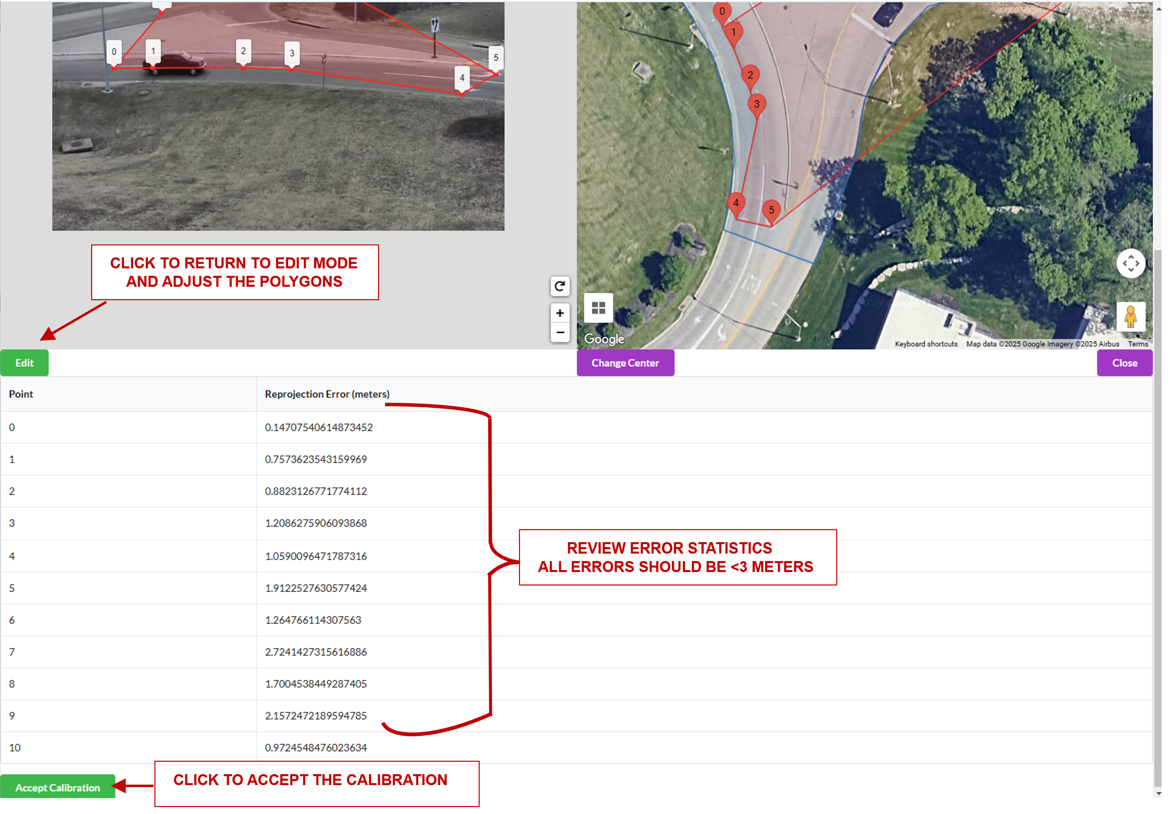
Further notes on reprojection error: The reprojection error is calculated by projecting a point in the image polygon (point 1 on the image polygon), to satellite coordinates. The distance (meters) between that point, and the corresponding point drawn on the satellite image (that is, point 1 on the satellite image in the case that point 1 on the image polygon was projected to satellite coordinates), is the reprojection error for that point correspondence.
Validation#
Sensor Validation is used as a tool to evaluate the homography matrix generated at the calibration step. Validation is necessary, as simply having accurate reprojection errors does not guarantee the homography matrix will work for all locations in the image. The aim is to validate that the homography matrix is valid for possible car trajectories in the area of our ROI.
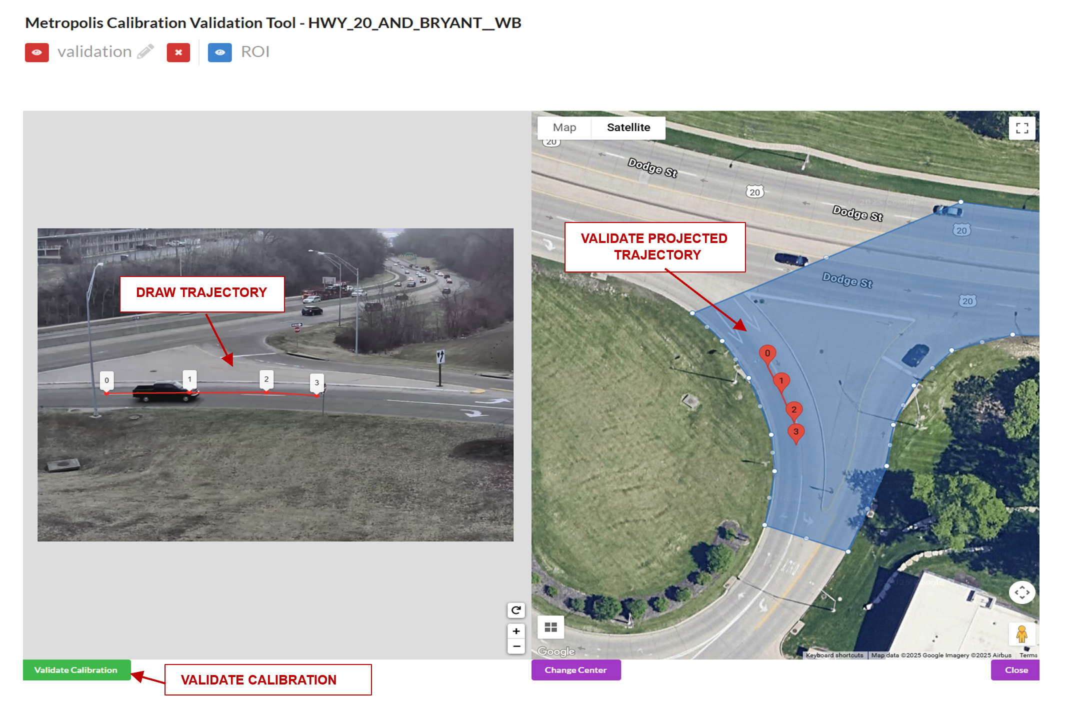
To validate, we will draw test trajectories that a car could feasibly drive in the image and the app will automatically project the trajectory to the satellite map. The trajectory does not need to be a legal driving path, but should be feasible in the sense that a car could drive in the locations along the trajectory. The main idea is that the if we draw a trajectory in the eastbound lanes on the image, it should project to the eastbound lanes on the map. Or, if we draw a trajectory in the westbound lanes on the image, it should project to the westbound lanes on the map.
A good validation will test all parts of the Region of Interest as well as all parts of the Camera’s Field of View to see that the calibration holds up.
How To Validate#
Load the Validation Tool
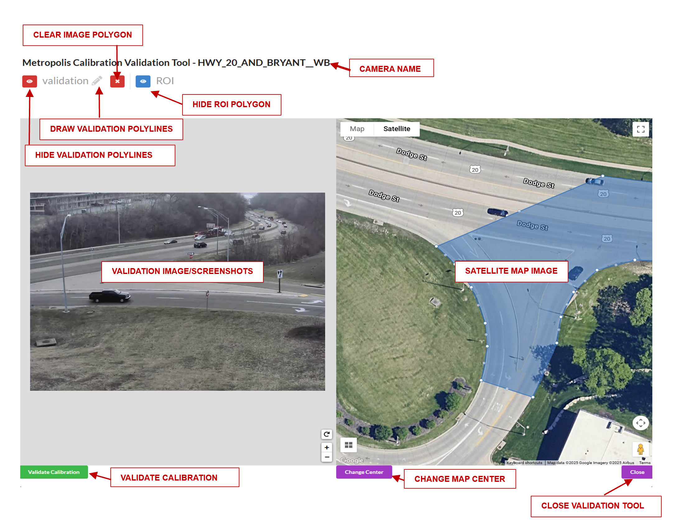
Draw a trajectory on the image, and validate that the projected polyline makes sense in the satellite map. Feel free to clear the image and try drawing as many trajectories as desired. Validate the Calibration when satisfied.
Road Link and Corridor for GIS Calibration#
This App allows us to generate the Road Links that will show up in the UI. In essence, we need to draw lines on the satellite map that represent the intersections we are interested in. We will then be able to query the corresponding links from the Open Street Maps. Find the open street maps from https://download.geofabrik.de/ . We are looking for the .bz2 file.
Road Link Generation#
Once we have calibrated all the cameras, and added them to the correct intersection, we are ready to generate the Road Links. In this view, we will be drawing line segments, to generate the links that show up in the UI. It may be helpful to revisit the cameras in the intersection to visualize the roads that the intersection covers.
Edit the Intersection and choose to Edit Road Links.
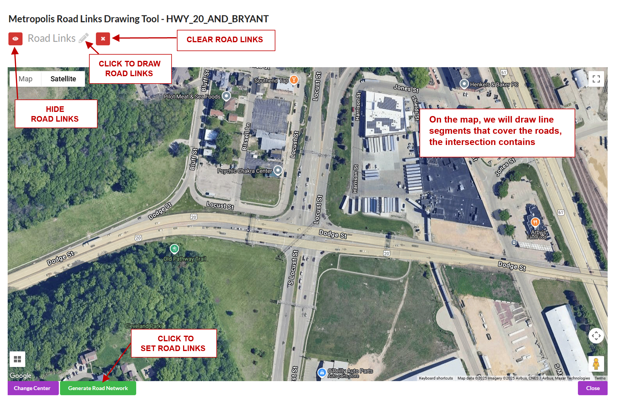
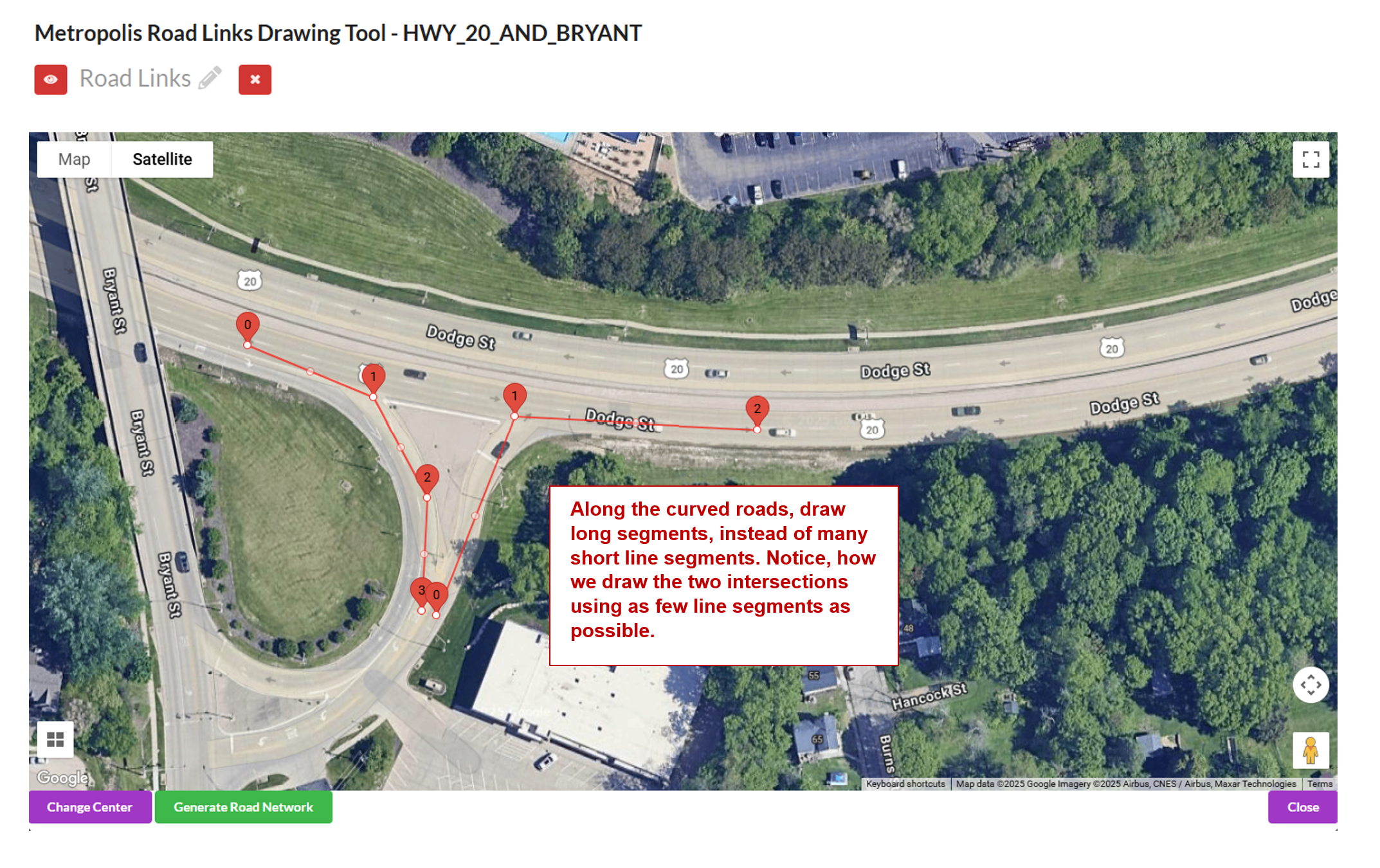
When we are drawing, we want to draw line segments that correlate to the roads being seen by the cameras in that intersection. For each road in the camera, there needs to be a line drawn, that starts where a car would be coming from to where it is going. For example, a road going north:
When drawing the line segments, we want to draw them in terms of the whole intersection. For instance, if you have a northbound and southbound camera, then you can draw 2 line segments one SB and one NB.
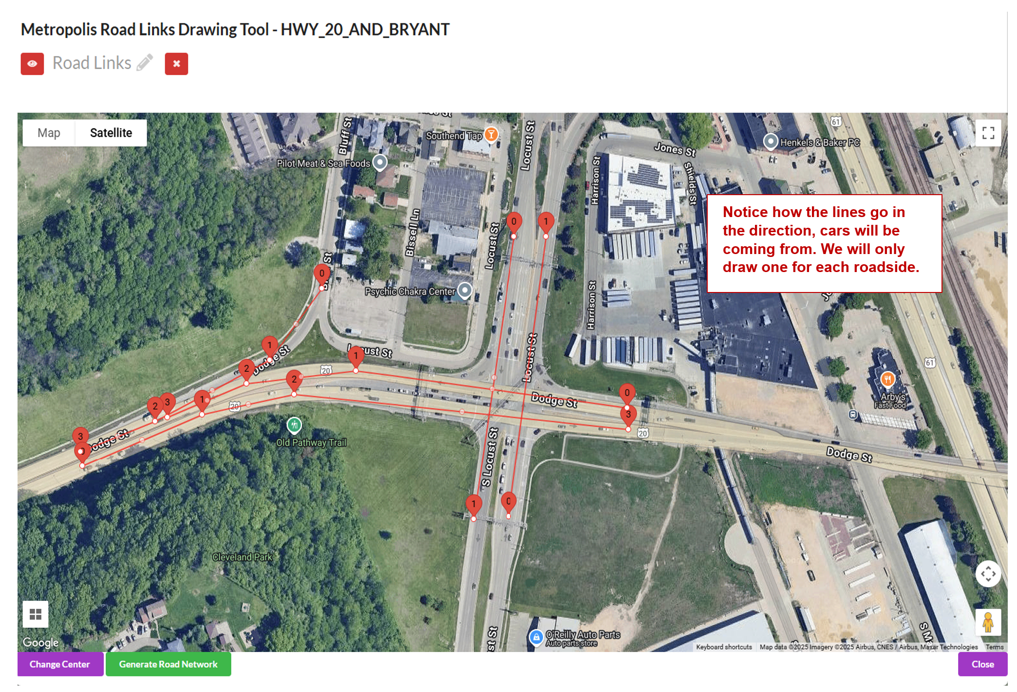
When the intersections are curved, draw few long line segments instead of many short line segments as follows to get more accurate results:
Road Link Validation#
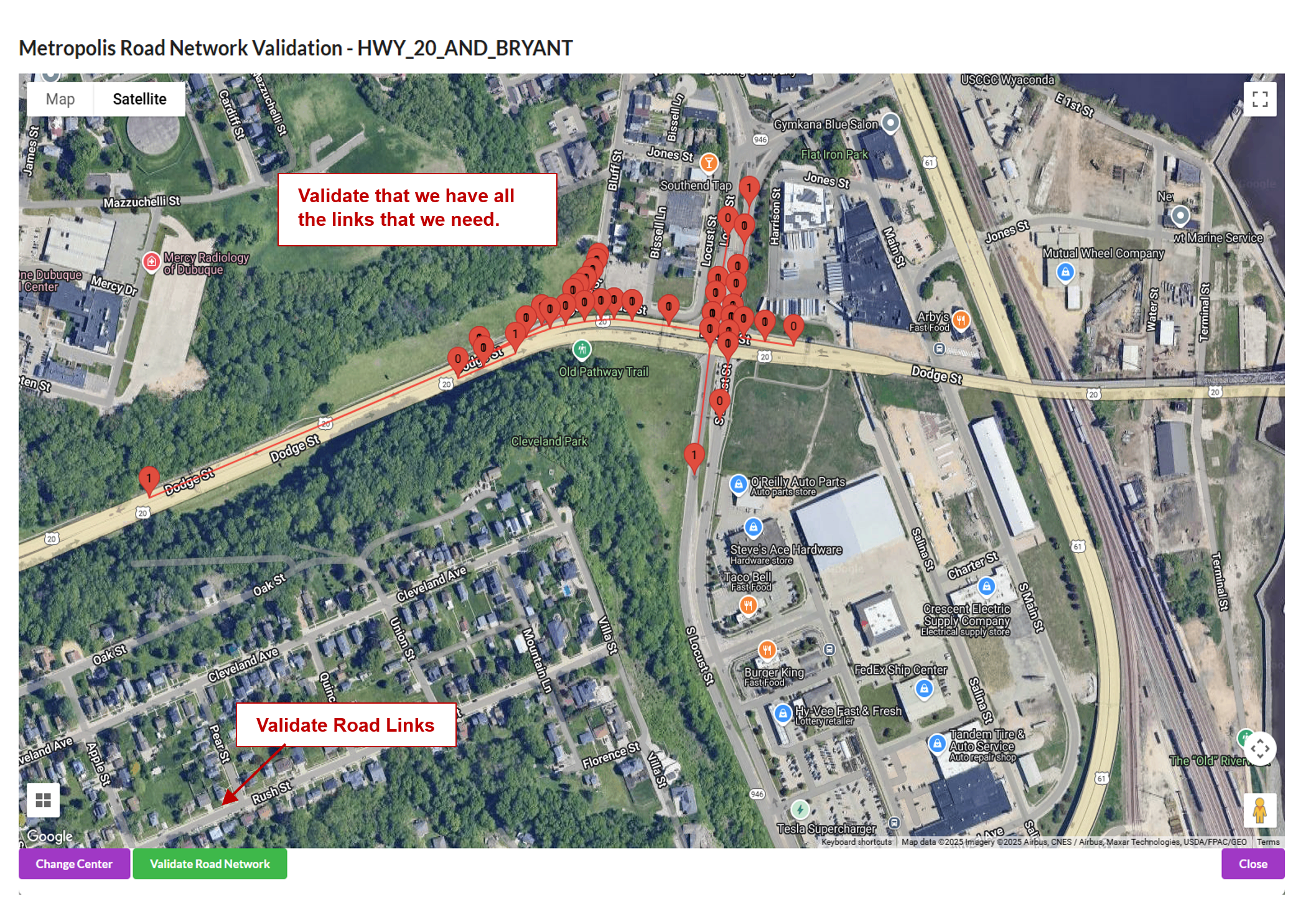
After generating the links, this will enable us to load the links that we will see in the application UI, and validate that we have all the links that we need. Notice that the line segment markers go in increasing order in the direction that cars will be moving. For one way roads, make sure there is only one link. It is possible that the links do not match up cleanly. This is an issue with the granularity of the Open Street maps.
Notice, the generated links along the curved roads which were drawn with few line segments.
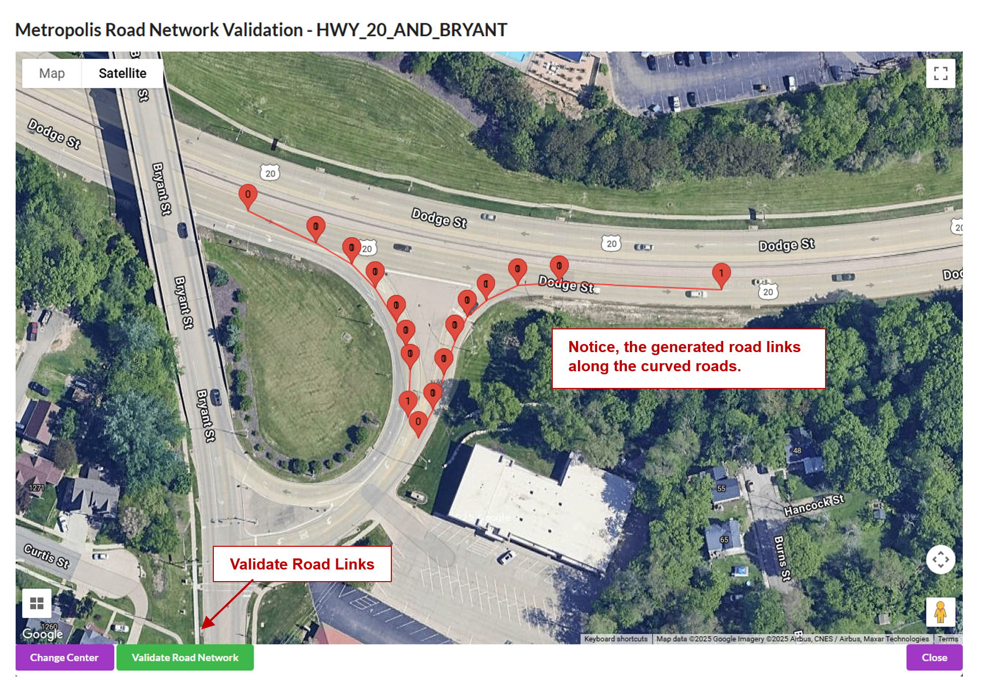
If they are valid, click “Validate Links” to validate the links.
Corridor Data Generation#
A corridor is a way of grouping cameras along the same road. Cameras assigned to a specific corridor should automatically appear in the corridor map view.
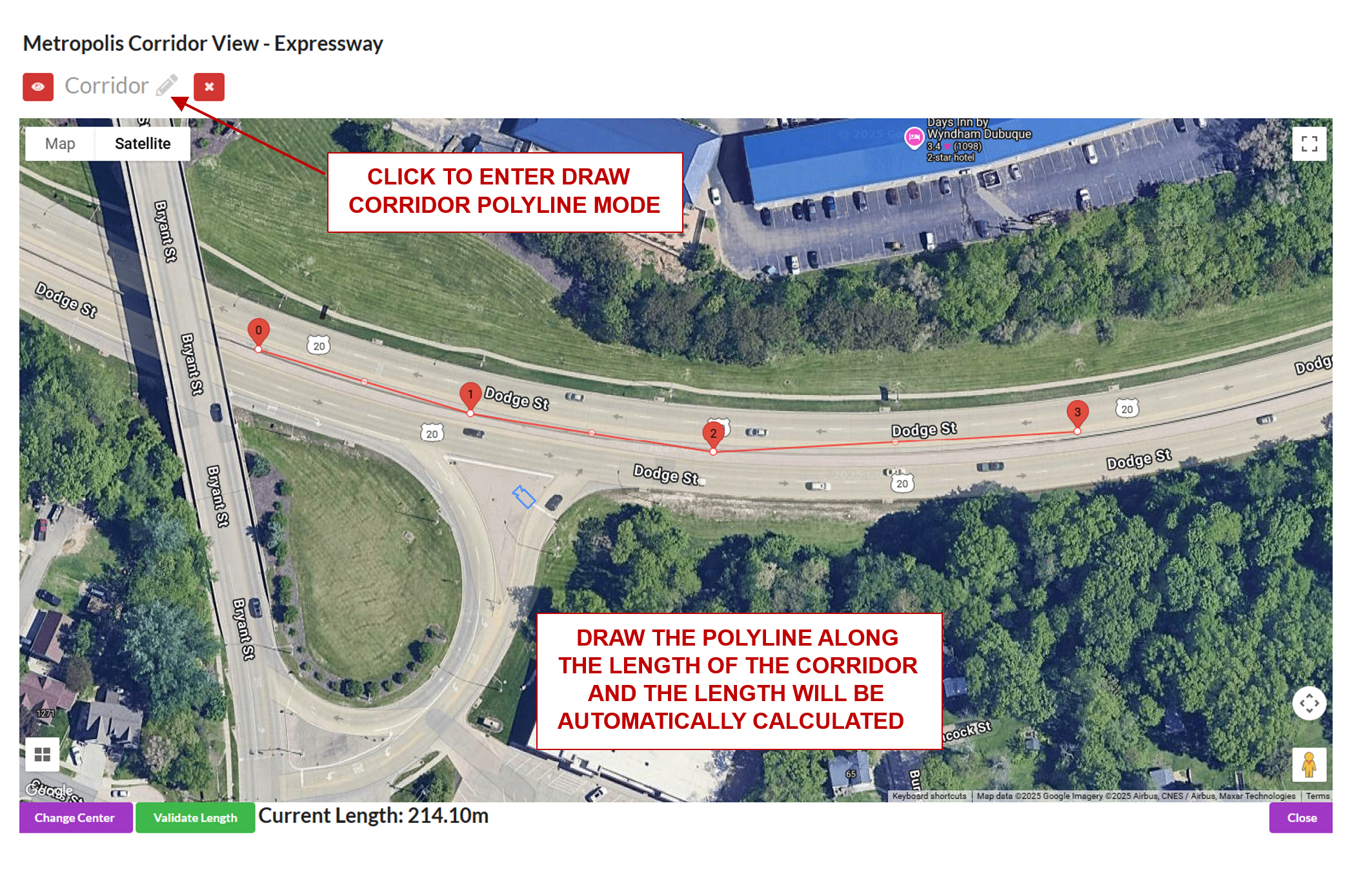
One main attribute of a corridor is the corridor length. To generate the length, a polyline is drawn along the road that covers all cameras along the corridor (the polyline does not need to touch the camera, but simply pass by it). The app will automatically calculate and display the length after drawing.
Load the corridor view. In this view you can see all cameras that belong to the chosen corridor.
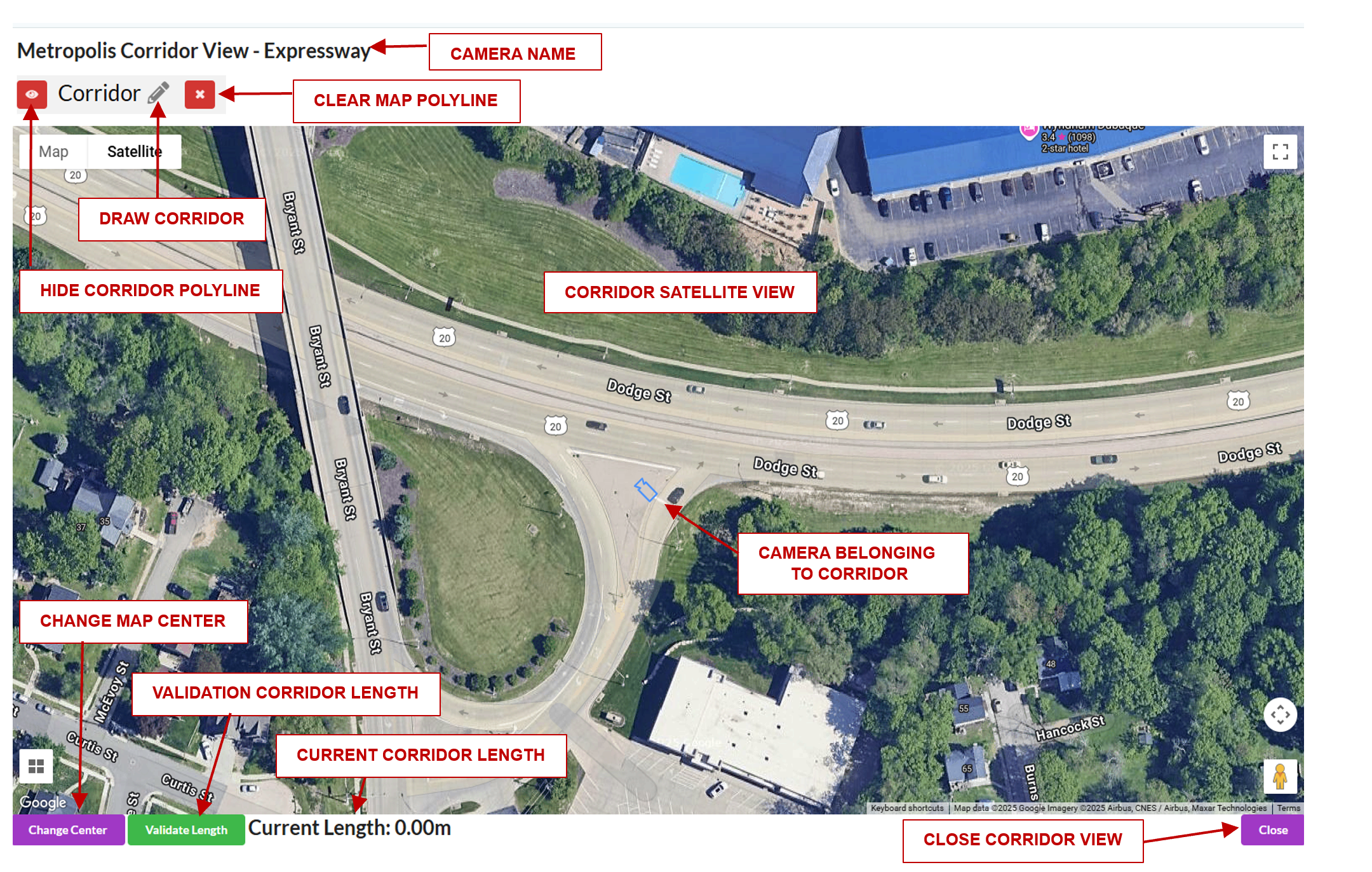
Click a camera to get more information. This can be used to confirm the correct cameras are in the corridor.
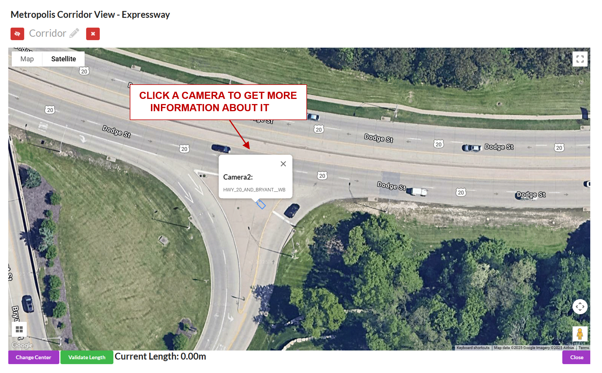
Draw a line along the length of the corridor. When the line is drawn, the length (in meters) of the corridor will automatically be calculated.
Export#
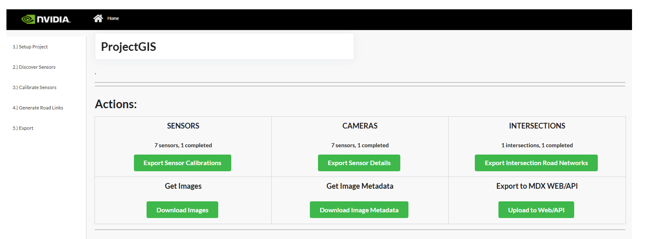
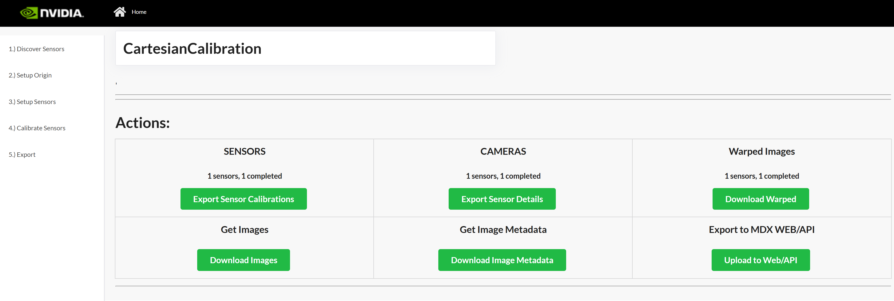
Export Sensor Calibration#
Click Export Sensor Calibrations to generate the calibration.json. It will include all validated cameras in your project. The file will download to the Downloads folder on the user’s computer.
Export RoadLink Network#
Click Export Intersection Road Networks to generate the network.json. It will include all validated intersections and their respective road links, which will be populated in the application UI. The file will download to the Downloads folder on the user’s computer.
Export Sensor Details#
Click Export Sensor Details to generate the sensorMetadata.csv which includes all the sensors and the associated details needed for the Video Analytics API. The file will download to the Downloads folder on the user’s computer.
Export Images#
Click Download Images to generate a zip file Images.zip containing all the uploaded sensor images. The file will download to the user’s specified Downloads folder on the user’s computer.
Export Image Metadata#
Click Get Image Metadata to generate a imageMetadata.json file containing the metadata of all the uploaded sensor images. The file will download to the user’s specified Downloads folder on the user’s computer.
Project Type - Multi-Camera Tracking#
Multi-camera Tracking Calibration allows us to define a 1:1 mapping between a camera and a floor plan or building map. In this type of calibration, we will use at least 8 points in the pixel space and matching 8 points in the floor plan domain to calibrate sensors. We will calibrate a sensor to a crop of the floor plan that corresponds to that sensor.
Floor Plan Setup#
Upload a floor plan of the place being calibrated. This will be used to make sure the correlation between camera and floor plan is consistent. After uploading a floor plan and importing the cameras, the sensors need to be placed on the floor plan. After uploading a floor plan, it may take some time for the floor plan to sync across all cameras. During this time, you will not be able to upload a new floorplan.
For each sensor, place a sensor on it’s location on the floor plan.
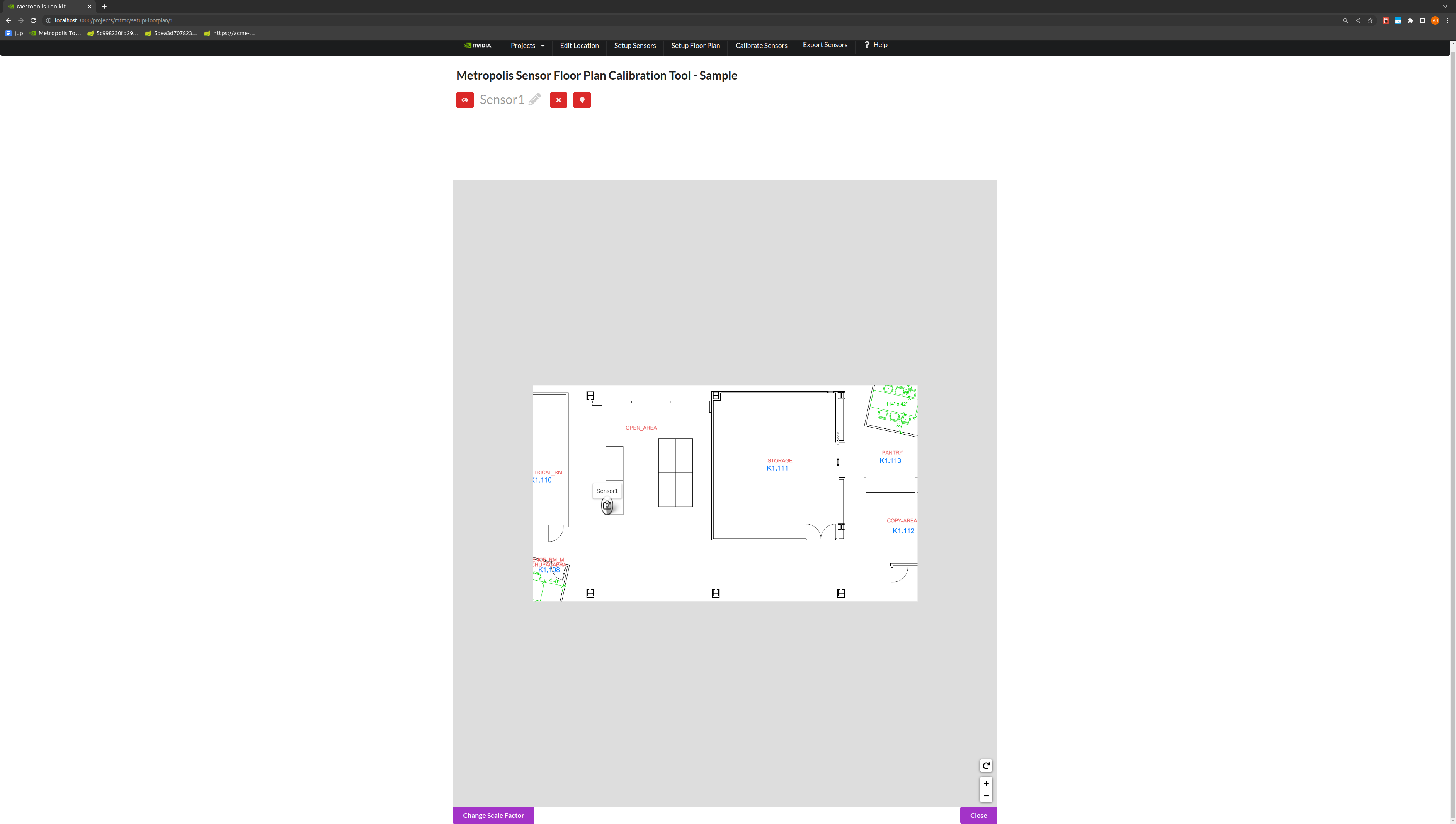
Toggle the Change Scale Factor button, to add a Scale Factor between pixels to meters.
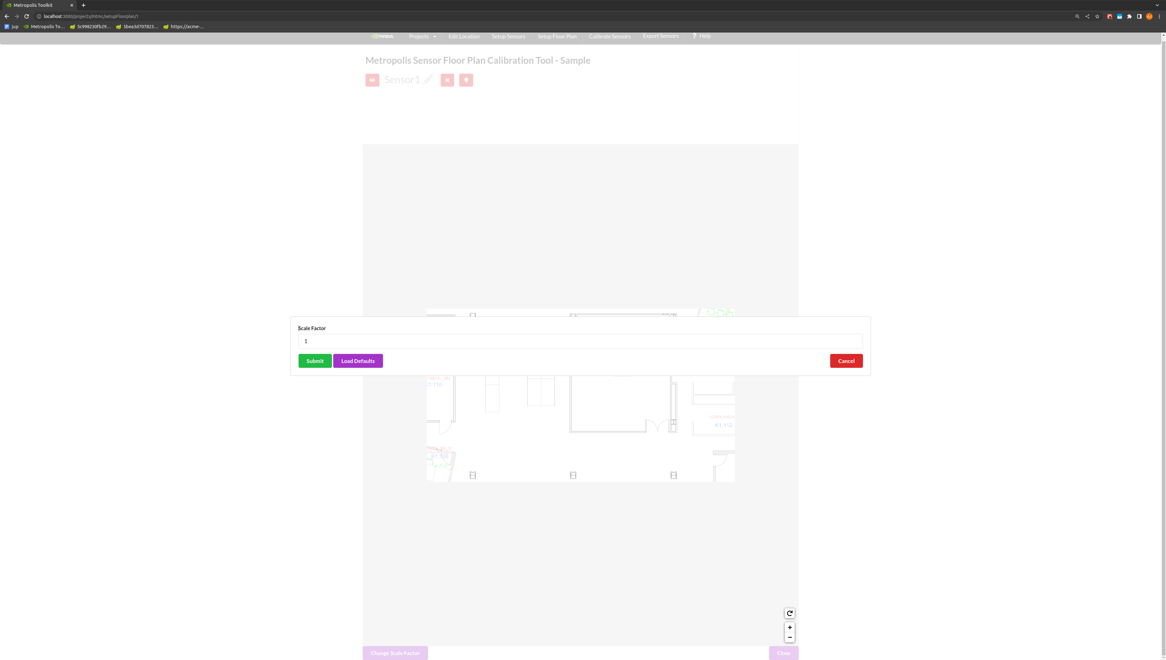
Note
The global coordinates in the final calibration output file is suppose to be in “meters” and the scale factor is “pixel/meters”. Global coordinates in meters is for providing the analytics-streams ease to calculate distances between objects and other metrics. Scale factor is for UI to scale the “meters” back to floor plan pixel scale for visualization.
Use the toggle markers button for better visibility on the exact location of a point.
Calibration#
Generate Homography Matrix#
Draw a polygon of at least 8 landmark features that can be seen in both the image and the floor plan view. The best practice is to start drawing from the bottom left of the image, and to add points in a counter-clockwise fashion.
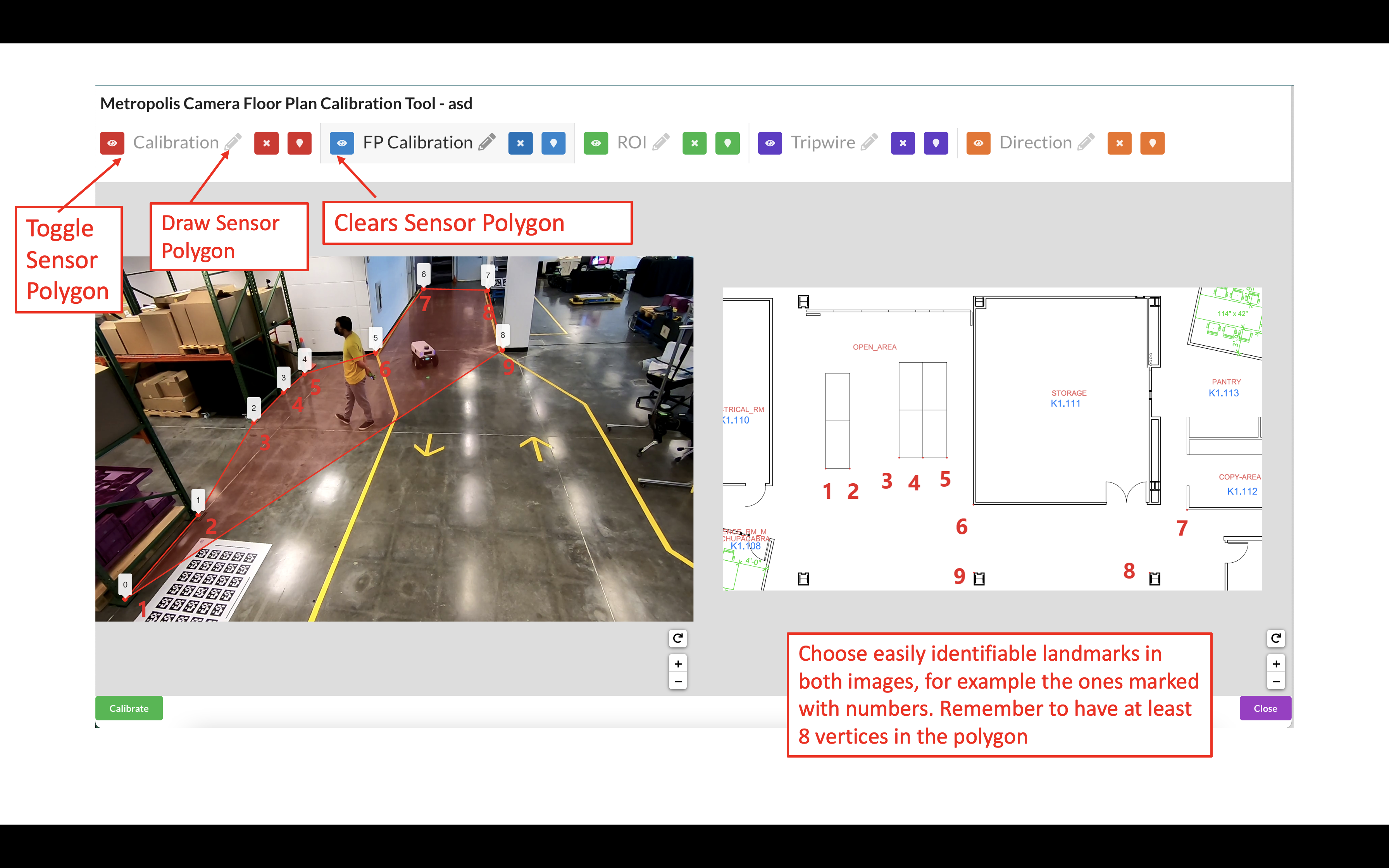
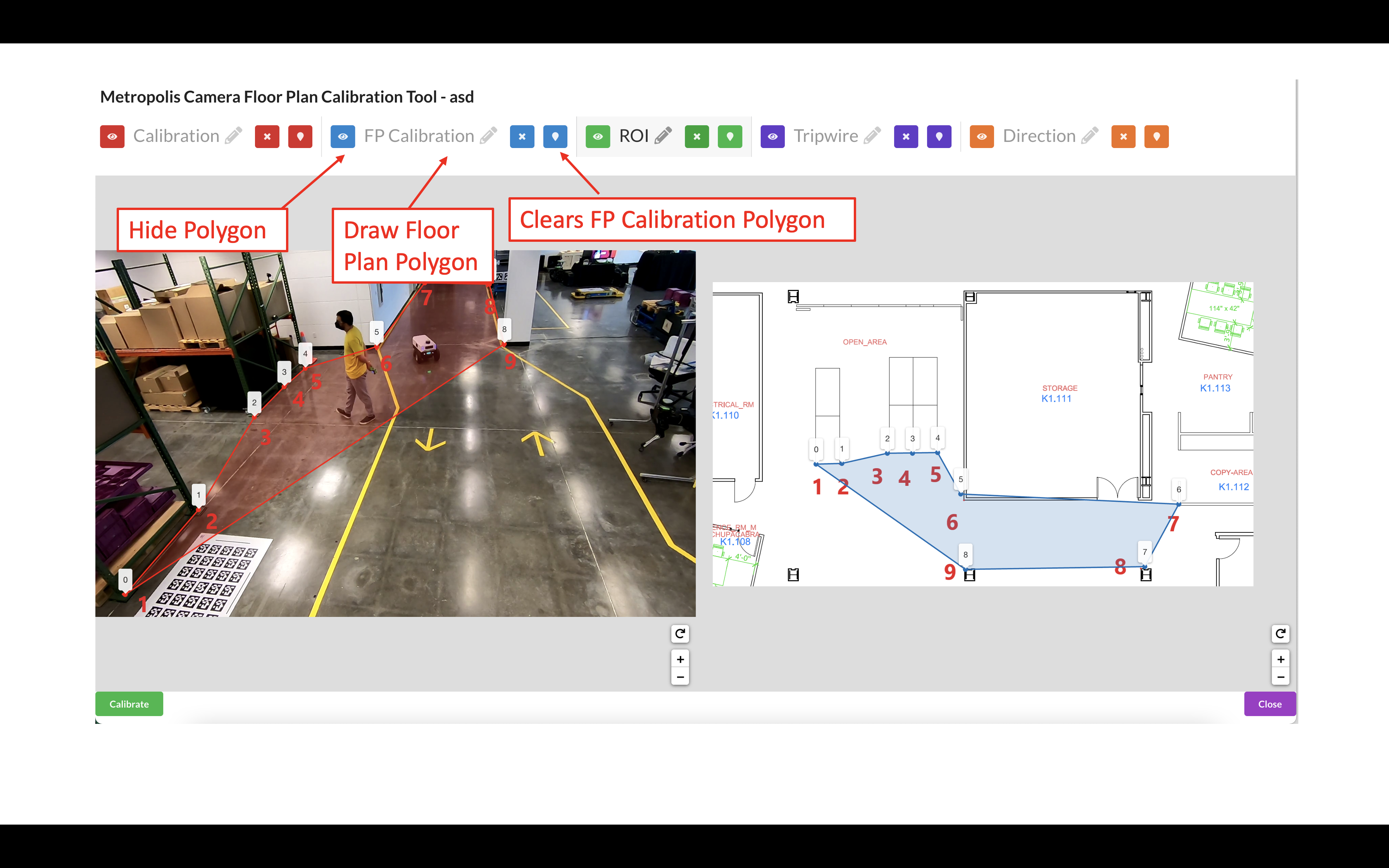
Draw a polygon on the Multi-Camera Tracking floorplan map with landmark features that match the polygon in the image.
Use the toggle markers button for better visibility on the exact location of a point.
Draw the Region of Interest (ROI), which represents the area for which the calibration is intended to be valid. This does not necessarily have to be the sensor’s entire Field of View.
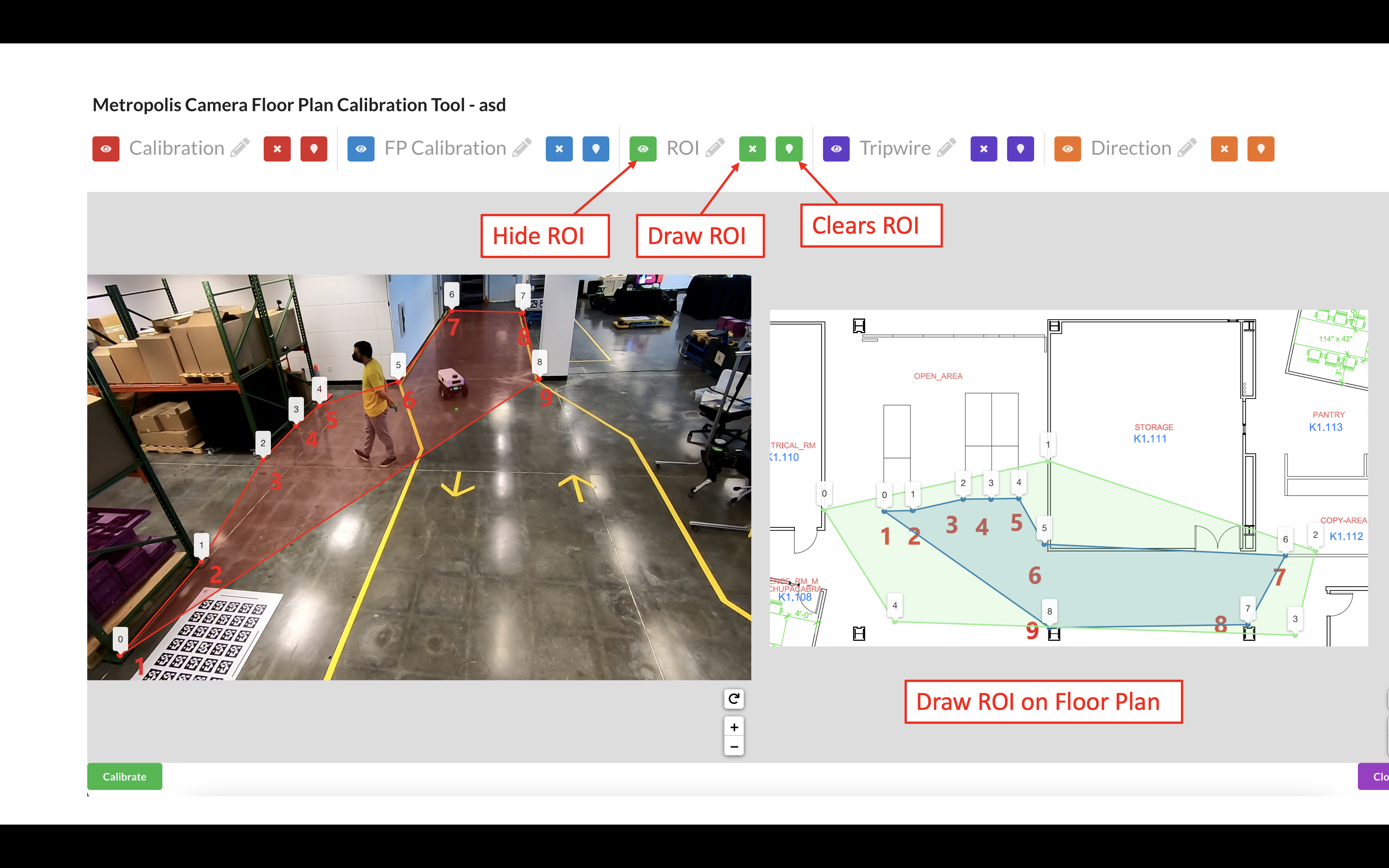
Further notes on the Region of Interest (ROI): The homography matrix from the calibration relies on the assumption that the area is flat, and so the calibration is expected to produce erroneous results in non-planar areas. Therefore, the ROI should cover the parts of the room that the camera can see, so the end application knows to ignore points outside this region. This helps prevent errors and improve performance. The ROI can be further adjusted at the Camera Validation step as the user will learn more about how well the calibration works in certain areas of the image.
Use the toggle markers button for better visibility on the exact location of a point, or to hide the specified polygon or polyline.
Click the Calibrate button to calculate the homography matrix.
Review the reprojection errors of the points. Click edit to go back and adjust points, or Accept Calibration to accept the homography matrix.
More on reprojection error: It is calculated by finding the Euclidean distance between the point and it’s corresponding projected point. The distance (meters) between that point, and the corresponding point drawn on the floor plan/map image (point 1 on the real world image in the case that point 1 on the image polygon was projected to the floor plan coordinates), is the reprojection error for that point correspondence.
Add Tripwires/Direction#
Tripwires/Directions are not used by the Multi-Camera Tracking reference app. For Multi-Camera Tracking app you can skip the step of configuring tripwires in calibration toolkit (please do read the important notes under the following Multi-Camera Tracking Validation section).
(For advanced users) If you have a floor plan for your Occupancy Analytics (OA) app and want to use Multi-Camera Tracking Calibration (aka calibration with floor plan) to draw tripwire/direction for that OA app, please refer to Adding Tripwires/Direction in Cartesian Calibration section below.
Validation#
The validation step / logic is similar to the validation step in GIS calibration. Instead of projecting the trajectory onto a satellite map, it will project the trajectory onto the floor plan map.
Validate the Images#
Load the Validation Tool.
Draw a trajectory on the image, and validate that the projected polyline makes sense in the transformed image. Feel free to clear the image and try drawing as many trajectories as desired. Validate the Calibration when satisfied.
The ROI, Tripwire, and Direction lines will be projected onto the real world image. To adjust these lines, go back to the Project Type - Multi-Camera Tracking section.
Project Type - Cartesian#
Cartesian Calibration allows us to define a linear mapping (perspective transformation) between a camera and a virtual plane without a pre-defined floor plan map. In this type of calibration, we will use the 4 anchor points (or more) in the pixel space and a user defined coordinate system to calibrate sensors. In Cartesian Calibration, you must add a origin latitude and longitude, as well as the name of the city and a room. The origin could be the city’s lat and long.
Calibration#
Generate Homography Matrix#
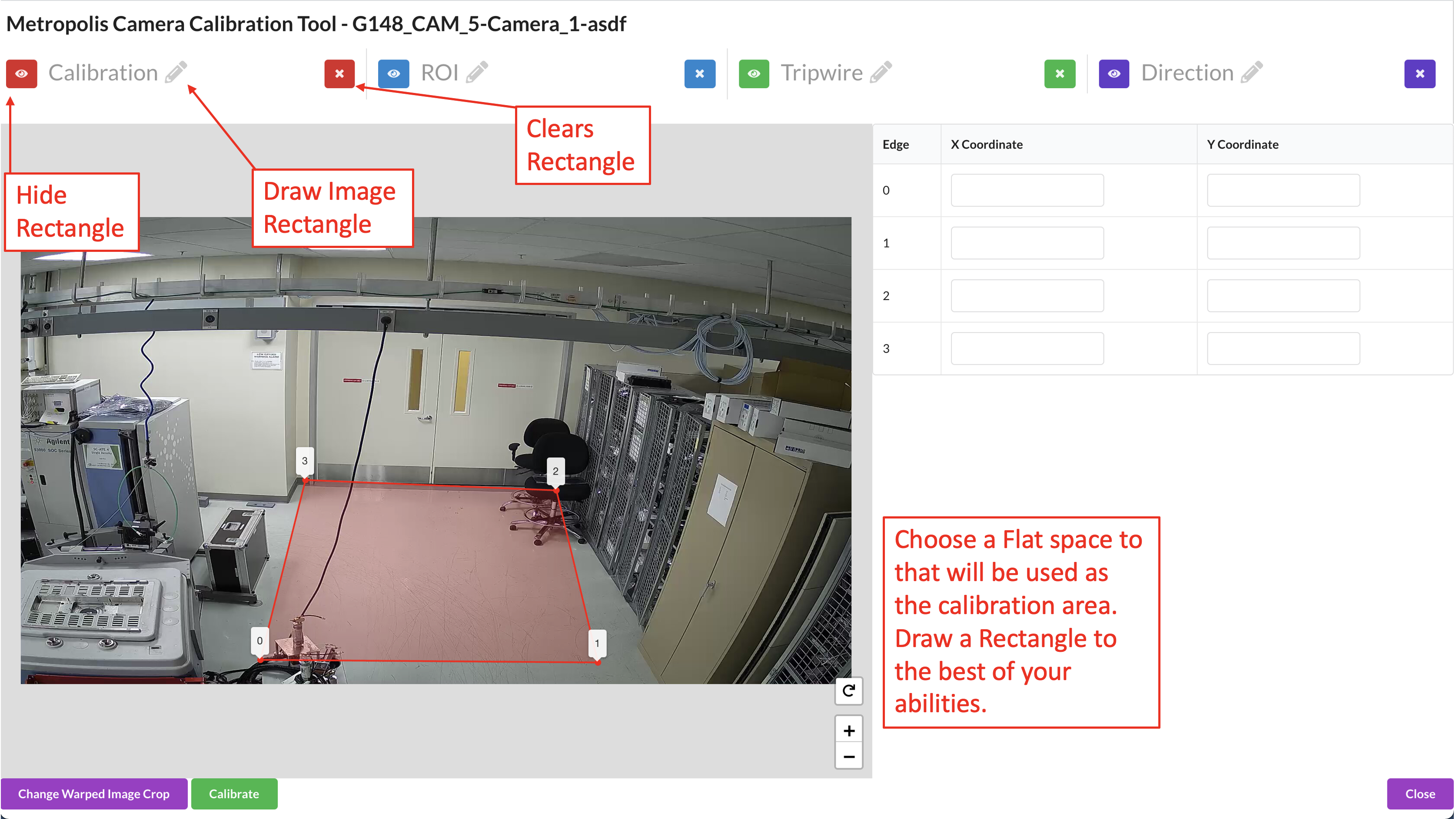
Draw 4-Point Rectangle.
To Generate the camera calibration, the first step is to draw 4 anchor points on a flat space in the image. The best practice is that the selected 4 anchor points forms a rectangle in the real world so that it is easier to estimate the real-world coordinates of these anchors in the next step. There is no actual restrictions on the anchor points selection. User may select any anchor points, if user has physical access to the monitored environment and has a way to properly measure the real-world coordinates for the selected anchor points.
Note
The goal here is to find a 2D-to-2D linear mapping (perspective transformation) between the floor plane in the camera view and the floor plane in the target cartesian coordinate system.
Assumptions here are two folds:
camera view is without distortion and
the floor surface is flat. Distorted camera view or non-flatness of the floor surface will lead to systematic inaccuracy.
Under the above assumption, we recommend to use only 4 anchor points. If you have a slightly distorted camera view or slightly un-flat floor surface, the inaccuracy might be tolerable and in that case you can use more than 4 anchor points to generate the homography matrix. You can select anchor points near the area of interest since the estimated homography matrix is minimizing the error near the anchor points.
Define the Cartesian Coordinate System.
On the left side, for each point drawn, you’ll see two boxes with the x and y coordinate which defines that point in the coordinate system. Approximate the distance between the points in centimeters, and define your coordinate system based on the (x,y) distance from your origin.
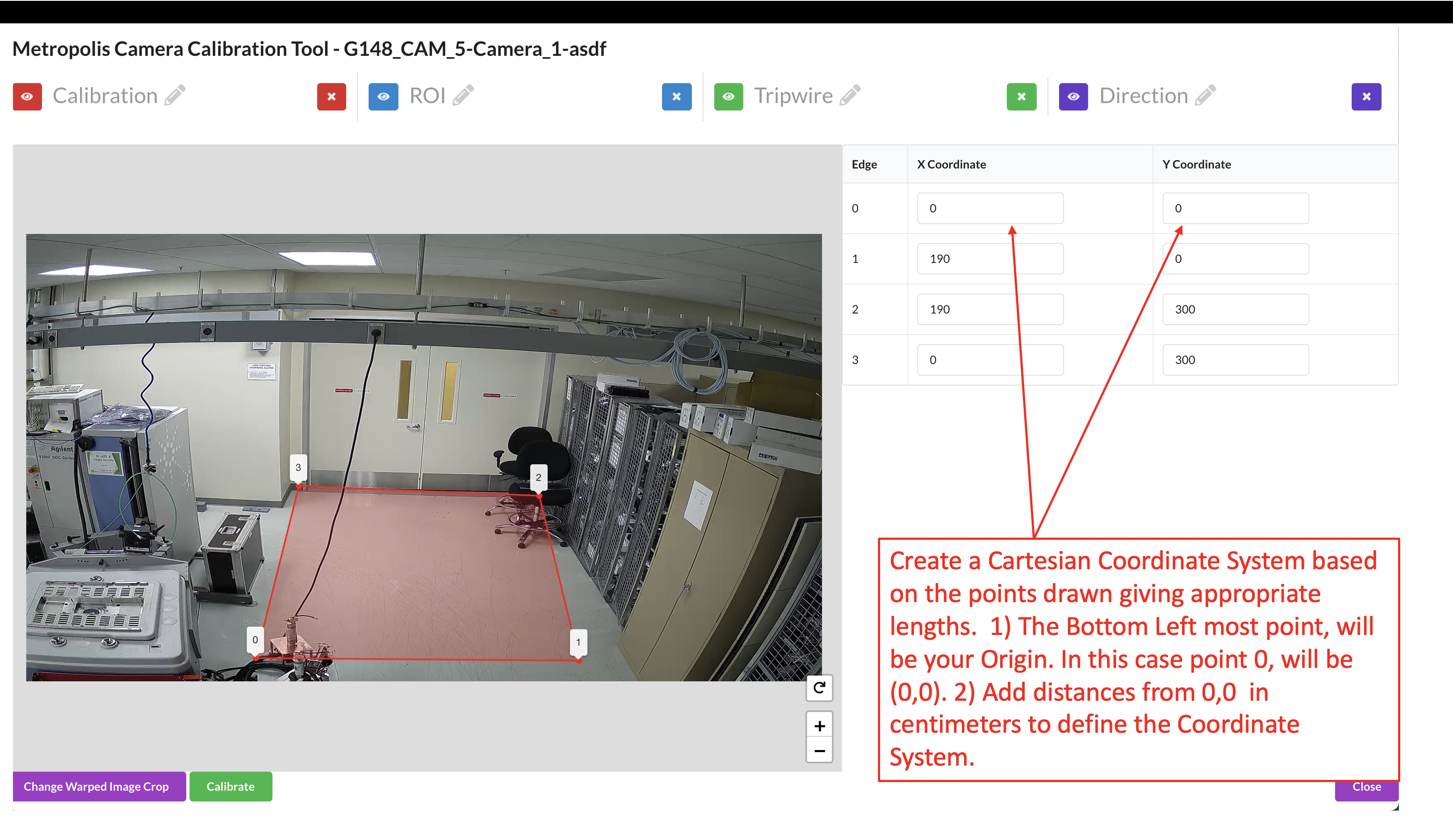
The Bottom Left point will be the first point (0,Y Max), the second point will be (X Max, Y Max), the third point will be (X Max, 0), and the last point, top Right, will be the origin (0,0). If you already have a coordinate system in mind, for example (0, 0) is a corner of the room, and you have ways to measure and compute the (x,y) coordinates of the 4 anchor points, you can just use your own coordinate system and input the (x,y) coordinates directly in the boxes.
Click the Calibrate button to calculate the homography matrix.
Review the reprojection errors of the points. Click edit to go back and adjust points, or Accept Calibration to accept the homography matrix.
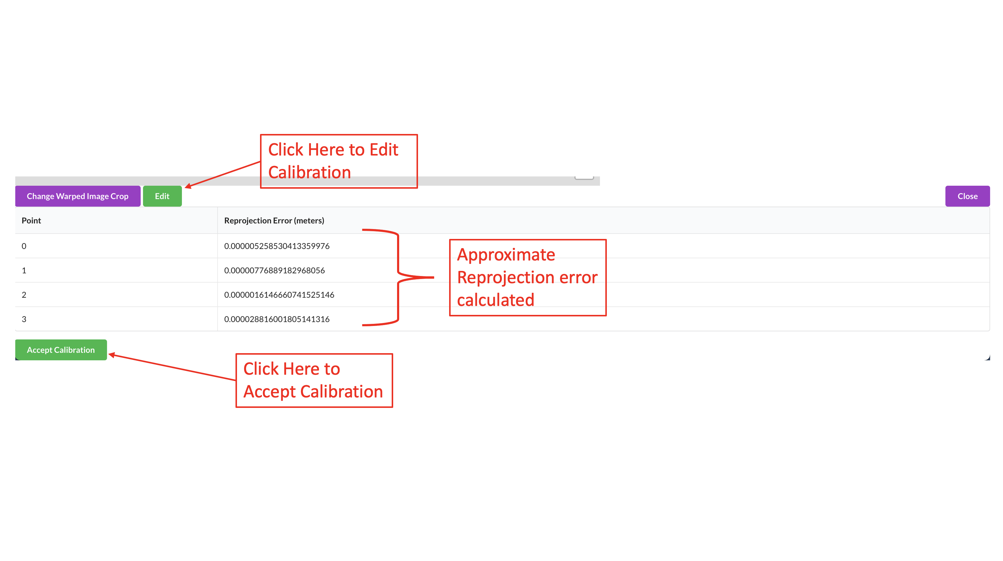
The reprojection error is calculated by finding the Euclidean distance between the point and it’s corresponding projected point. The distance (meters) between that point, and the corresponding point projected from image domain, is the reprojection error for that point correspondence. Computation step is as follows:
We have a set of anchor points, their pixel coordinates (x,y) and their cartesian coordinates (X,Y).
Homography matrix M is computed from (x,y) and (X,Y)
For each anchor point, we apply M to (x,y) and get a re-projected (X’,Y’).
The distance between (X,Y) and (X’,Y’) is the reprojection error for that anchor point.
Note
The reprojection error only reflects if the anchor points “agree” with each other and it doesn’t reflect right or wrong of the calibration. In this cartesian calibration, if only 4 anchor points are used, the reprojection error will always be small. To actually validate the calibration and have a sense of if the calibration works, user should check if the warped image makes sense, described in the validation section below.
Add Region of Interest (ROI)#
You can add Regions of Interest (ROI) depending on your application.
In some applications, the ROI can be used as a filter to ignore detections outside the ROI. This is generally useful since many practical factors can cause certain detections be unreliable and we want to use ROI to filter them out. In some other application, the ROI can be used not just for filtering detections, but also for triggering events or computing ROI related metrics. You can draw ROI in any ways but below points are worth considering:
The area farther away from the calibration anchor points has low calibration accuracy when camera view is distorted or the floor surface is not flat.
The area too far away from the camera itself can has low detection accuracy thus you may want to avoid.
The area in the camera view that are not flat, such as stairs, sloped terrain, etc. and we want to exclude them from the ROI.
Draw the Region of Interest (ROI). This does not necessarily have to be the sensor’s entire Field of View.
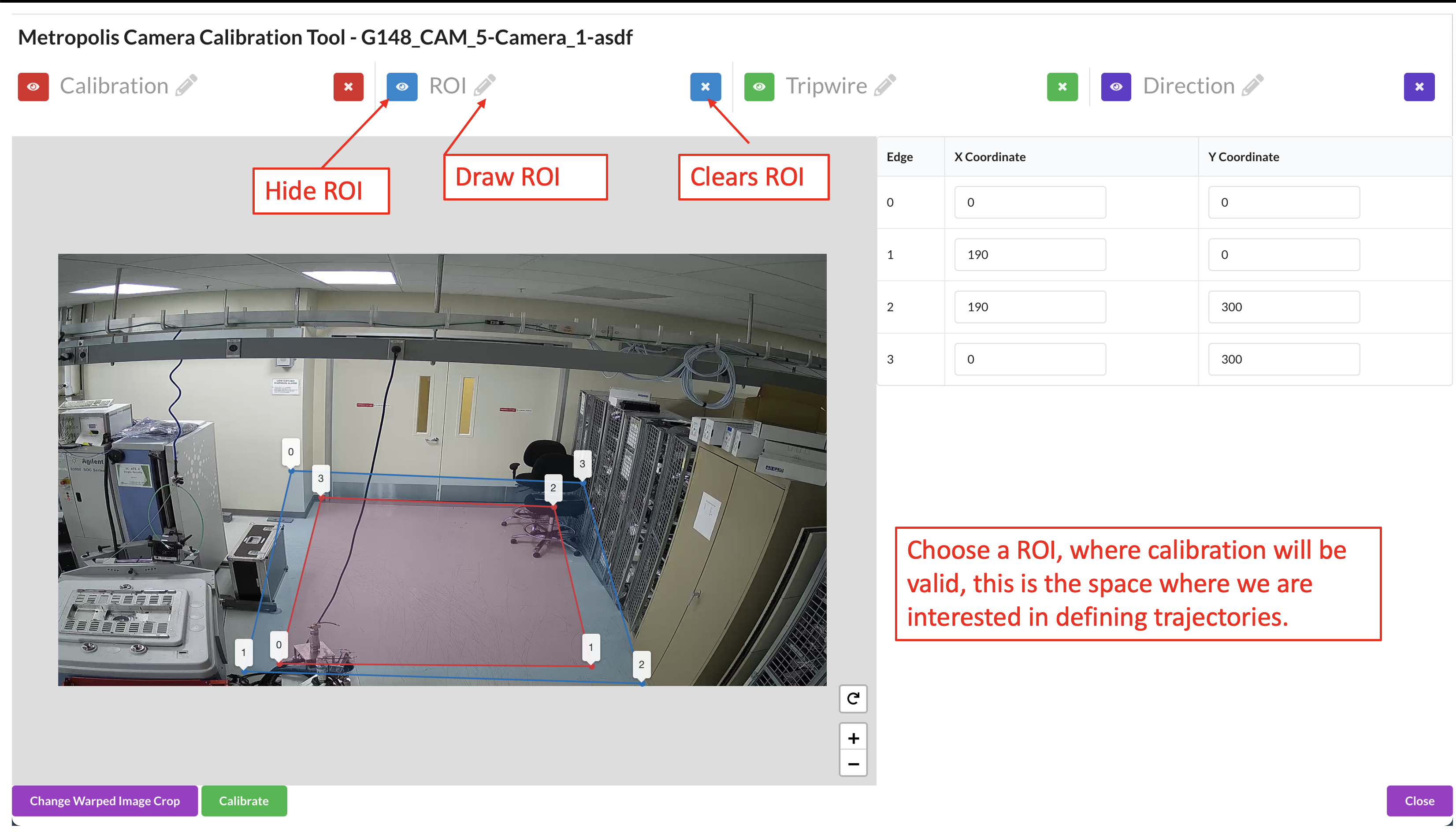
The ROI can be further adjusted at the Sensor Validation step as the user will learn more about how well the calibration works in certain areas of the image.
Use the toggle markers button for better visibility on the exact location of a point, or to hide the specified polygon or polyline.
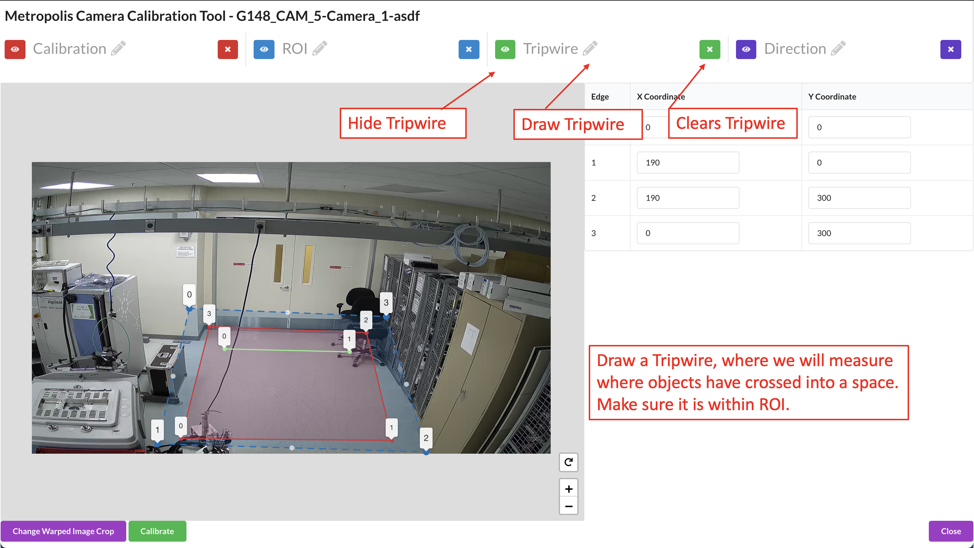
Add Tripwires/Direction#
You can add tripwires depending on your application. Tripwires are used to trigger events when objects cross the tripwire and monitor counts.
Draw the tripwire.
Draw a line segment that defines the region where we want to detect if objects have crossed. Make sure that the polyline has only 2 points.
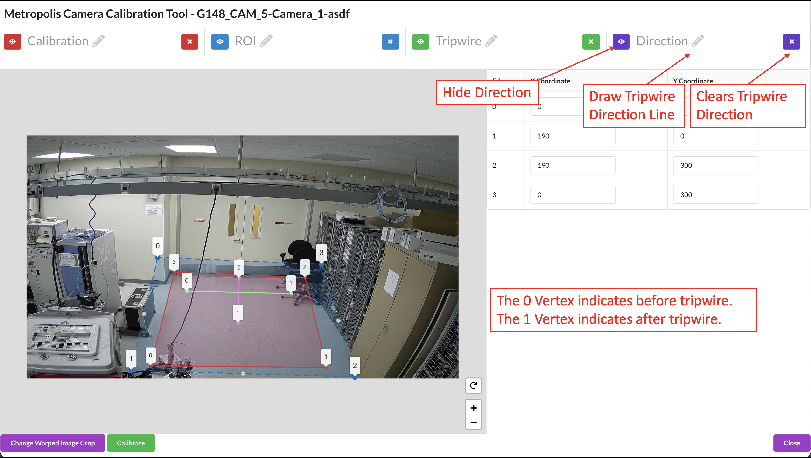
Draw the Tripwire Direction Wire.
When we are drawing, we want to draw line segments that correlate to the direction that objects will be entering the tripwire. This line must intersect the tripwire line. From Point 0 to Point 1 is the OUT direction and from Point 1 to Point 0 is the IN direction. Make sure that the polyline has only 2 points. The direction line is used to determine “in” vs “out” when counting objects crossing the tripwire.
Validation#
Generate Warped Image#
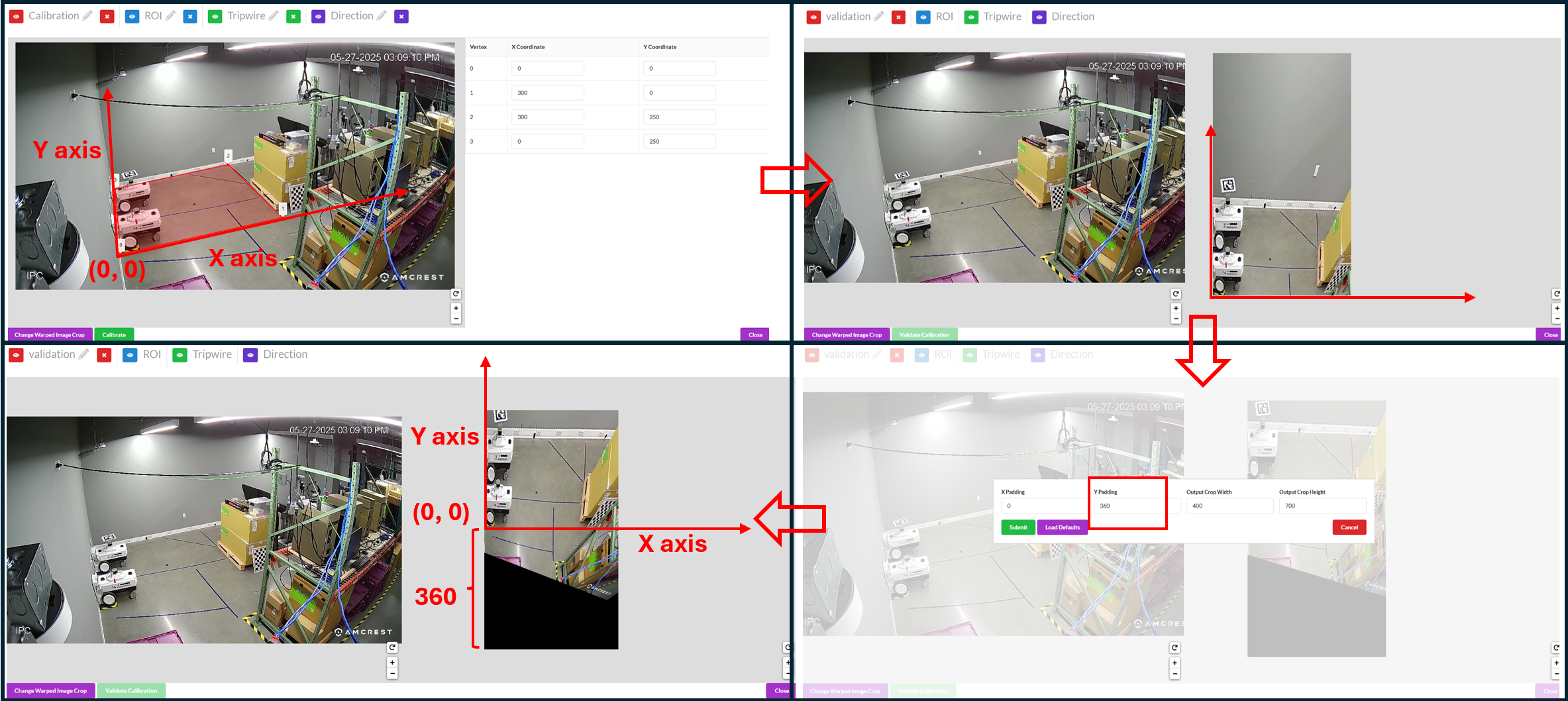
In the Cartesian calibration, we don’t have the google map in the GIS calibration or the floor plan map in the Multi-Camera Tracking calibration. Instead, after anchor points selection the tool auto-generates a warped image which is suppose to be a top-down view of the area and can be used as a floor plan map. The warped image is shown in the validation window.
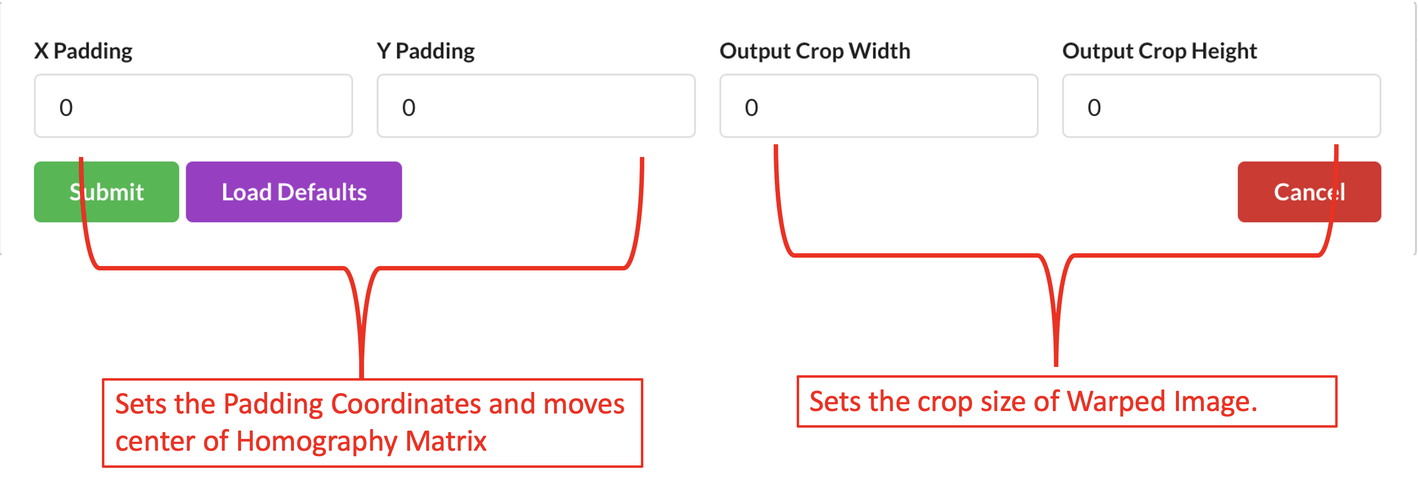
We can adjust the warped image by padding pixels which moves the center of the crop taken, and adjusting the size of the crop.
The warped image helps you understand better the monitored area and the quality of the calibration so understanding the warped image is important for the camera validation step.
Below we show two examples of calibration and the corresponding warped image to give users a better understanding.
Example 1:
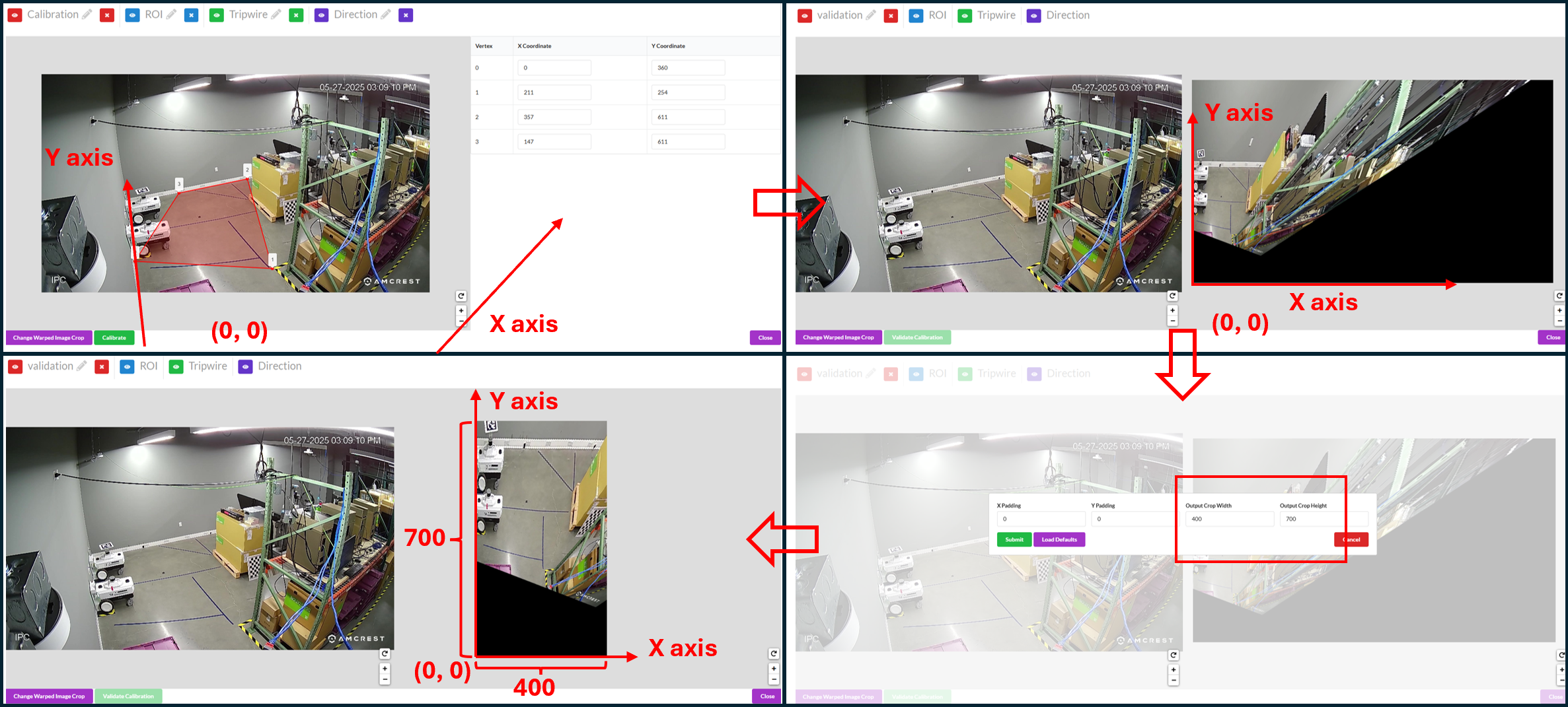
The top-left window shows the selected anchor points of the calibration. In this example, the anchor points don’t form a rectangle in the real-world. We have physical access to the monitored environment and we measure the real-world coordinates for the selected anchor points while using the bottom-left corner of the zoom as the origin. The indication of x axis, y axis and the origin is shown in the picture (the origin is actually outside the camera view).
The top-right window shows the corresponding warped image with default width and height (1920 x 1080). The origin of the Cartesian coordinate system is at the bottom-left corner of the warped image and since the origin is outside the camera view, you see blank / black areas in the warped image. Since we centimeter is the unit when we give cartesian coordinates when selecting anchor points, the warped image size is also in centimeters. In this case, the warped image represents an area of 1920 cm x 1080 cm area (19.2 m x 10.8 m).
Since our area of interest is close to the corner of the zoom, between the wall and the shelves, we want to crop the warped image to focus more on the area of interest. We can do this by setting crop width and crop height as shown in the bottom-right window.
The bottom-left window shows the new warped image with updated crop width and height. This new warped image just focuses on the area between the wall and the shelves and represents a 400 cm x 700 cm area (4 m x 7 m).
Example 2:
The top-left windows shows the selected anchor points of the calibration. In this example, we assumes we don’t have physical access to the room thus we follow the best practice to choose anchor points that form a rectangle, use the bottom left one as the origin and estimate the length in centimeters. The indication of x axis, y axis and the origin is shown in the picture.
The top-right windows the corresponding warped image with updated width and height (400 x 700).
The cartesian origin is the bottom-left corner of the warped image and since the cartesian origin is within camera view, some part of the camera view is cut off in the warped image. We can add padding to include the area in the negative side of x and y axis as shown in the bottom-right window.
The bottom-left window shows the new warped image with updated paddings. This new warped image focuses on the area of interest without cutting off camera views.
Validate the Images#
The functionality of the validation tool is the same as the other calibration type and for the validate steps please refer to the validation step in GIS calibration or validation step in Multi-Camera Tracking calibration.
Validating Cartesian calibration can be challenging due to a fundamental difference in its validation logic compared to GIS and Multi-Camera Tracking calibrations. In the latter two, a world map is available for reference, whereas in Cartesian calibration, the “world map” is the warped image generated from the calibration process itself. Consequently, any point selected from the image view will always correspond to the same location on the warped image. For instance, if you select the corner of a wall in the image view, the projected point on the warped image will also appear at the corner of the wall.
Therefore, the validation criterion is not whether the projected point lands on the correct location on the map, as the map is derived from the calibration. Instead, the focus is on whether the derived map, or warped image, accurately represents a top-down view. Using the previous example, rather than verifying if the projected point remains at the corner of the wall (which it will), we should ensure that the corner of the wall forms a 90-degree angle in the warped image.
Project Type - Image#
Project Type - Image allows us to define ROIs, and tripwires for a sensor without any homography calibration.
Generating the Artifacts#
Draw the Region of Interest (ROI), which represents the area for which the calibration is intended to be valid. This does not necessarily have to be the sensor’s entire Field of View.
Use the toggle markers button for better visibility on the exact location of a point, or to hide the specified polygon or polyline.
Adding Tripwires/Direction#
In calibration, we are able to add tripwires to enable counting.
Draw the tripwire
Draw a line segment that defines the region where we want to detect if objects have crossed. Make sure that the polyline has only 2 points. When we are drawing, we want to draw line segments that correlate to the direction that objects will be entering the tripwire. This line must intersect the tripwire line. From Point 0 to Point 1 is the OUT direction and from Point 1 to Point 0 is the IN direction. Make sure that the polyline has only 2 points as shown in the above image.
Export Artifacts#
Camera Calibration#
Click Export Sensor Calibrations to generate the calibration.json. It will include all validated cameras in your project. The file will download to the Downloads folder on your computer. If you must, you can rename, add, or remove the places for each sensor. You can use a common text editor to edit them.
Export Sensor Details#
Click Export Sensor Details to generate the sensorMetadata.csv which includes all the sensors and the associated details needed for the Video Analytics API. The file will download to the Downloads folder on your computer.
Export Warped Images#
Click Download Warped to generate the Warped Images.zip which includes the warped images for each camera which has been calibrated and validated. The file will download to the Downloads folder on your computer.
Image Metadata#
Click Download Image Metadata to generate the imageMetadata.json which includes metadata for each image. The file will download to the Downloads folder on your computer.
Images#
Click Download Images to generate the Images.zip which contains the image for each sensor. The file will download to the Downloads folder on your computer.
Consume Artifacts#
To consume the calibration.json and other Calibration Toolkit artifacts, one way is to use the Video Analytics API /config/upload-file/calibration endpoint.
It inserts the config file into Video Analytics API. For Behavior Analytics, these artifacts are passed via command-line to transforming image coordinates to cartesian coordinates as well.
Customization#
To help understand more and potentially customize the toolkit, refer to the source code provided in the camera calibration toolkit module directory.