Calibration#
Camera calibration is an essential step to enable using cameras as sensors for analytics with Metropolis systems. It involves obtaining a homography matrix for projecting points from camera image coordinates, (i.e. pixel coordinates), to the global satellite space (i.e. latitude/longitude co-ordinates). Calibration is required because analyzing object movement in geo coordinates rather than image based coordinated enables more accurate spatial analysis of vehicle location, and movement attributes such as trajectory and speed, while also being able to map it road links where the vehicles are moving.
This release describes use of a web based tool to enable manual calibration of cameras based on correlating points between image (through camera snapshot) and geo coordinates (through Google Map). In addition, a preview of using digital twin to facilitate camera calibration based on a semi automated process is also described.
Calibration Toolkit#
The Metropolis Camera Calibration Toolkit is a React/Python web application that provides a manual, point-based approach to GIS camera calibration. It enables users to map pixel coordinates in camera images to latitude/longitude coordinates using Google Maps satellite imagery.
How It Works:
The toolkit generates a 3x3 homography matrix by having users draw matching polygons of at least 8 landmark points in both the camera image view and the satellite map view. These corresponding anchor points—static features visible in both views—allow the system to compute the perspective transformation needed to project detected objects from image space to geo-coordinates.
This calibration is essential for the Smart City Blueprint where vehicle tracking requires geo-referenced positions to calculate real-world metrics like speed and to map trajectories onto road links.
Calibration Workflow:
Sensor Setup: Add cameras with metadata including sensor ID, geo-location, cardinal direction, and video stream URLs.
Group Configuration: Organize cameras into Intersections (cameras covering the same road crossing) and Corridors (cameras along a highway or arterial road) for UI grouping.
Draw Calibration Polygons: In the camera image, draw a polygon marking at least 8 landmark features (road markings, curbs, lane boundaries). Then draw a matching polygon on the satellite map identifying the same landmarks.
Define Region of Interest (ROI): Draw the area where calibration is valid—typically the road surface visible to the camera.
Calibrate: Click the Calibrate button to compute the homography matrix. Review reprojection errors for each point.
Validate: Draw test trajectories on the camera image and verify they project correctly onto the satellite map.
Generate Road Links: Draw line segments on the satellite map representing traffic flow directions.
Export: Generate
calibration.json(calibration data),network.json(road links), andsensorMetadata.csvfor downstream applications.
Note
Only 2D calibration is supported (using a 3x3 homography matrix).
Cameras with significant lens distortion should be rectified before calibration, as the toolkit assumes an undistorted camera view.
The homography relies on the assumption of a flat road surface.
Requires a Google Maps JavaScript API key.
For detailed installation instructions, sensor configuration fields, step-by-step drawing guidelines with screenshots, and export procedures, refer to the Legacy Camera Calibration page.
Digital Twin-Based Camera Calibration#
Introduction#
The Digital Twin-Based Calibration Tool provides a mechanism for calibrating cameras deployed within a digital twin corresponding to a real world location. As an application of this, it can also be applied to calibrating cameras installed in the real world using their digital twin counterpart.
These calibration files are essential for downstream applications, particularly Smart City Blueprint (SCBP) pipelines, by enabling accurate mapping between 2D image pixels and real-world geographical coordinates.
The system’s foundation is the CARLA simulator, which provides a high-fidelity 3D environment. The tool provides three calibration paths:
File Upload Based Calibration: User creates calibration file by uploading a camera_specs.yaml file which contains metadata about the camera.
Precision Manual Calibration: User creates calibration file by manually adjusting a camera’s pose (position/orientation/fov …) while visualization it in the DT in realtime.
Accelerated Multi-Angle Setup: User selects calibration file(s) from a list of pre-calculated camera orientations to find an optimal pose quickly given a location.
System Architecture#
The system relies on a client-server setup with two primary components:
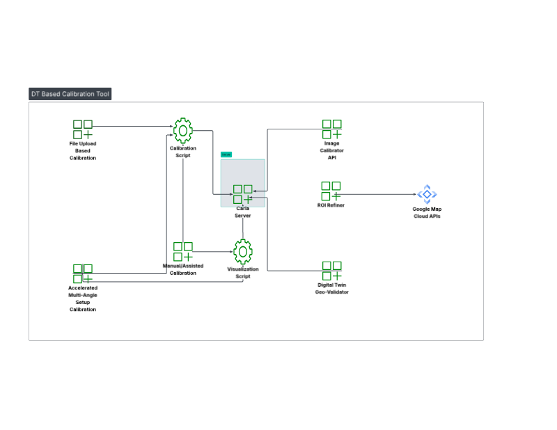
Component 1: CARLA Server
This is the core simulation engine that enables all calibration and visualization in the workflow.
Function: Hosts the 3D map (e.g., Town10HD or a custom
.xodrmap) and serves simulation data.Data Provided: Renders RGB, depth, and semantic segmentation sensor data on request.
Component 2: Calibration Client UIs
The system provides two separate web interfaces for different workflows, running on different ports.
Main UI (File Upload Based Calibration) - Port 7860
Function: This is the primary interface for the automatic calibration pipeline. It provides a “one-click” calibration solution.
Visualization Clients (Manual Assisted/Accelerated Multi-Angle Setup) - Port 7861
Function: This interface hosts two distinct tools for user-driven calibration. These clients connect to CARLA to provide a live visualization, allowing for a “visualize-then-create” workflow.
Setup and Installation#
Requirements:
Docker Compose
Accelerated computing
NVIDIA GPU Operator
Installation Steps:
Setup NGC Access
# Setup NGC access
export NGC_CLI_API_KEY={your NGC_CLI_API_KEY}
export NGC_CLI_ORG='nvidia'
Download the VSS DT Based Calibration blueprint project
# Setup compose
mkdir -p ~/vss-dt-based-calibration
cd ~/vss-dt-based-calibration

ngc \
    registry \
    resource \
    download-version \
    nvidia/vss-smartcities/vss-dt-based-calibration-compose:3.1.0

tar -zxvf vss-dt-based-calibration-compose_v3.1.0/deploy-dt-based-calibration-compose.tar.gz

rm -rf vss-dt-based-calibration-compose_v3.1.0
Prepare Your Map Archive
You have two options for providing a map, and they are not mutually exclusive:
Official CARLA Maps: These will be downloaded automatically by the command we provide.
Custom Map: Download the Montague map (Montague_0.9.16.tar.gz) from the AVES website AVES Reality and place it in this directory:
deployments/dt-based-calibration/calibration/
Configure the Command
Before running the script below, decide if you need the additional maps:
If you do NOT need carla additional maps: Comment out the two lines following
Import official additional mapssection within the command. CARLA includes several built-in default maps; however, these environments are synthetic and do not represent real-world locationsIf you do NOT need custom map either: Comment out the two lines following
Import a custom mapsection within the commandIf you are using a custom map: Ensure the file is already in the directory specified in
Prepare Your Map Archive
Execute the command to configure the Dockerfile
cd deployments

cat << 'EOF' > dt-based-calibration/calibration/Dockerfile
FROM carlasim/carla:0.9.16

USER root

# Disable audio warnings
ENV SDL_AUDIODRIVER=dummy
ENV DISPLAY=

WORKDIR /workspace

# install curl
RUN apt-get update && apt-get install -y curl

# Import official additional maps
RUN curl https://carla-releases.b-cdn.net/Linux/AdditionalMaps_0.9.16.tar.gz --output AdditionalMaps_0.9.16.tar.gz
RUN tar -xvzf AdditionalMaps_0.9.16.tar.gz && rm AdditionalMaps_0.9.16.tar.gz

# Import a custom map
COPY Montague_0.9.16.tar.gz .
RUN tar -xvzf Montague_0.9.16.tar.gz && rm Montague_0.9.16.tar.gz

USER carla

ENTRYPOINT ["/workspace/CarlaUE4.sh", "-carla-rpc-port=2000", "-carla-server", "-RenderOffScreen"]
EOF
Configure docker compose
Open this compose file
dt-based-calibration/calibration/compose.yamlLocate the CARLA server block and remove the comment markers to activate it
Update the context field to
./Update the dockerfile field to
./DockerfileUncomment the depends_on section for the dt-based-calibration service
Build and Start the App:
docker login \
    --username '$oauthtoken' \
    --password "${NGC_CLI_API_KEY}" \
    nvcr.io

docker compose --profile dt_based_calibration build

docker compose --profile dt_based_calibration up -d
Access the Web Interfaces:
File Upload–Based Calibration page:
http://<HOST_IP>:7860Manual/Assisted Calibration page:
http://<HOST_IP>:7861Image Calibrator API endpoint:
http://<HOST_IP>:7865Digital Twin Geo‑Validator page:
http://<HOST_IP>:8000ROI Refiner page:
http://<HOST_IP>:8080
Calibration Workflows#
This workflow explains how to generate a calibration file and validate your Digital Twin. The process follows this sequence: generate a calibration file (Workflow 1.A, 1.B, or 1.C) → refine the calibration file → optionally validate the map using the Digital Twin Geo-Validator.
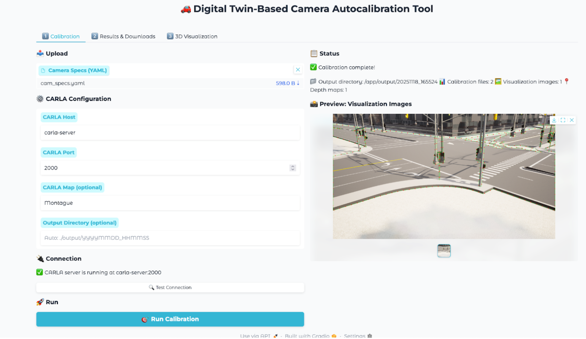
Workflow 1.A: File Upload Based Calibration (Port 7860)#
Steps:
Open
http://host-ip:7860in a browser.Create and Upload the
camera_specs.ymlfile. Go to Input Configuration section to see how to configure your specsEnter CARLA Map name corresponding to your
camera_specs.yml.Click the “Run Calibration” button. The process might take few seconds to complete.
Once the process is complete, go to the Results & Downloads tab.
Download the generated MDX JSON. and visualization files.
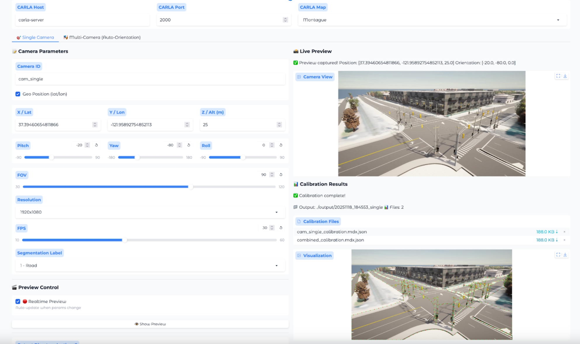
Workflow 1.B: Precision Manual Calibration (Port 7861)#
This workflow is for achieving the highest-fidelity manual alignment.
Steps:
Open
http://<HOST_IP>:7861and select the Precision Manual tool.Input the initial camera specs.
A live visualization from CARLA appears.
The user iteratively adjusts the position (Geo-coordinates) and orientation values in the UI, observing the visualization until it perfectly matches their real-world reference.
Once satisfied, the user clicks “Create Calibration File”.
The system generates the MDX JSON file based on these manually-entered parameters.
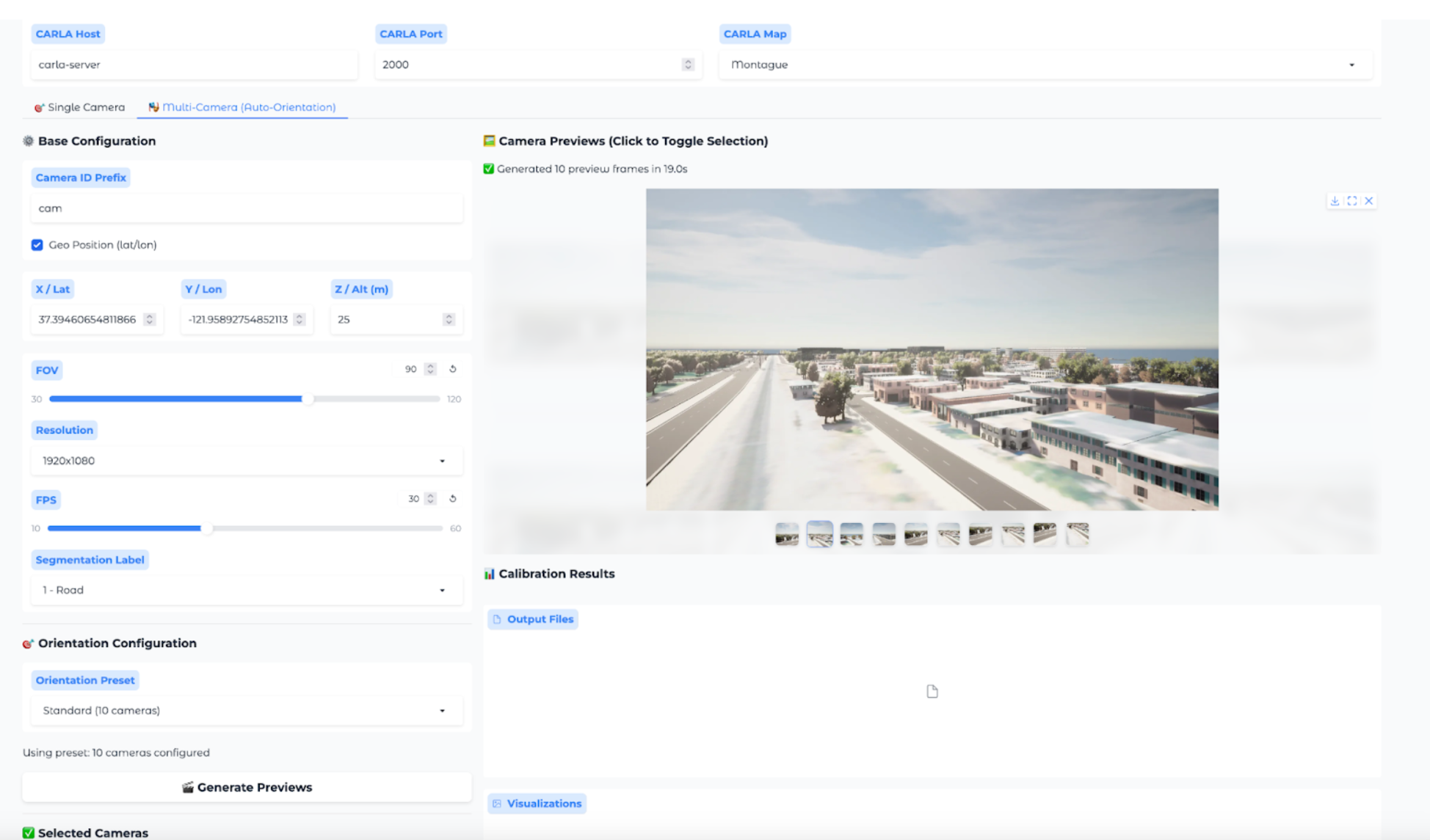
Workflow 1.C: Accelerated Multi-Angle Setup (Port 7861)#
This workflow is for rapid selection of a valid camera pose, often for Synthetic Data Generation (SDG).
Steps:
Open
http://<HOST_IP>:7861and select the Accelerated Setup tool.Input the initial camera specs.
The tool generates and displays multiple pre-calculated orientations.
The user clicks through the options and selects the best one.
Once satisfied, the user clicks “Create Calibration File”.
The system generates the MDX JSON file based on the selected parameters.
Input Configuration#
The File Upload Based Calibration is performed using a YAML file (camera_specs.yml). This file input contains the camera’s initial specifications including:
Camera position (world coordinates or geo-coordinates)
Camera orientation (pitch, yaw, roll)
Intrinsic parameters (focal length, image dimensions)
Map/scene information
You can have one or more camera specs in your camera spec file.
Sample camera_specs.yml
cameras:
 - id: cam_00 # Camera ID
   position: [804.8385330738965, -1387.7295602369122, 30] # x, y, z in CARLA world coordinates, or latitude, longitude, altitude in geographic coordinates.
   orientation: [-90, -30, 0] # pitch, yaw, roll in degrees
   fov: 60  # Field of view in degrees
   fps: 20
   resolution: [3840, 2160] # Width × height in pixels
   label: 1 # Road semantic-segmentation label ID used for extracting road information.
   geo_position: false # If position is in geographic coordinates, set to true; otherwise in world coordinate, set to false for world coordinates.
 - id: cam_01 # Camera ID
   position: [37.388529, -121.954532, 30] # x, y, z in CARLA world coordinates, or latitude, longitude, altitude in geographic coordinates.
   orientation: [-90, -30, 0] # pitch, yaw, roll in degrees
   fov: 90  # Field of view in degrees
   fps: 20
   resolution: [3840, 2160] # Width × height in pixels
   label: 1 # Road semantic-segmentation label ID used for extracting road information.
   geo_position: true # If position is in geographic coordinates, set to true; otherwise in world coordinate, set to false for world coordinates.
Output Files#
For each camera, the pipeline generates:
[id]_calibration.mdx.json: The primary calibration file. For single camera in the camera specs file.[id]_visualization.png: An image marking the 2D points (for automatic calibration).[id]_depth.npy: The raw depth map data.combined_calibration.mdx.json: A single file for all cameras, compatible with mdxui.combined_calibration_full.json: A detailed file with full matrices, used for the 3D web visualization.
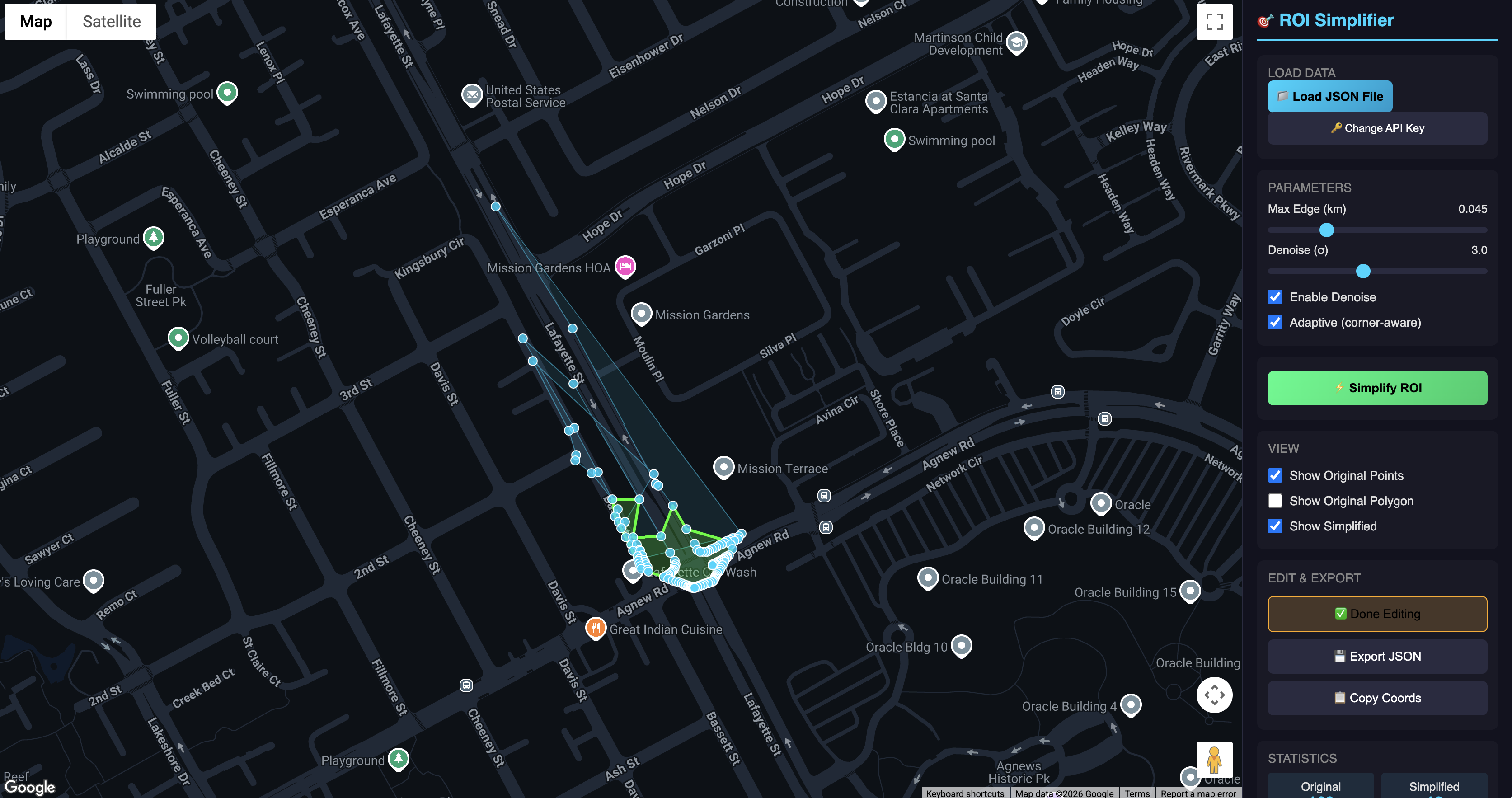
ROI Refiner#
The default ROI generated by the calibration tool is based on random FOV points and requires refinement. To get a proper ROI, utilize the dedicated ROI refinement service.
This service is accessible at http://<HOST_IP>:8080 and requires a Google Maps API key to function. The following shows a sample refinement for the Montague map.
Steps:
Open
http://<HOST_IP>:8080.Add your Google API key.
Upload the calibration file([id]_calibration.mdx.json/combined_calibration.mdx.json) to see the ROI visualized instantly.
Click the Simplify ROI button to automatically refine the ROI (manual tuning is also an option. Drag the white dot and move around).
Download the newly refined calibration file.
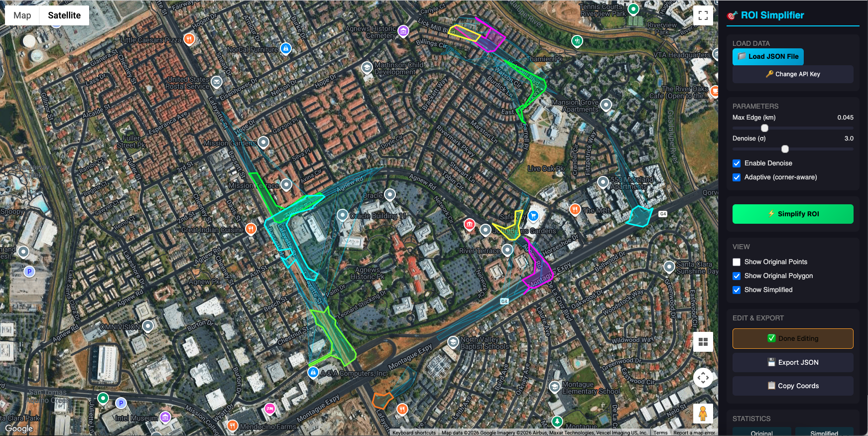
Before using this calibration file in your smart city blueprint pipeline, manually update the downloaded file with the City and Intersection names that match your Google Maps location. Please note that the downloaded file contains placeholder values that must be replaced.
If you upload a combined calibration file containing multiple camera specifications, the Regions of Interest (ROIs) for every intersection will be displayed as shown below.
Digital Twin Geo-Validator#
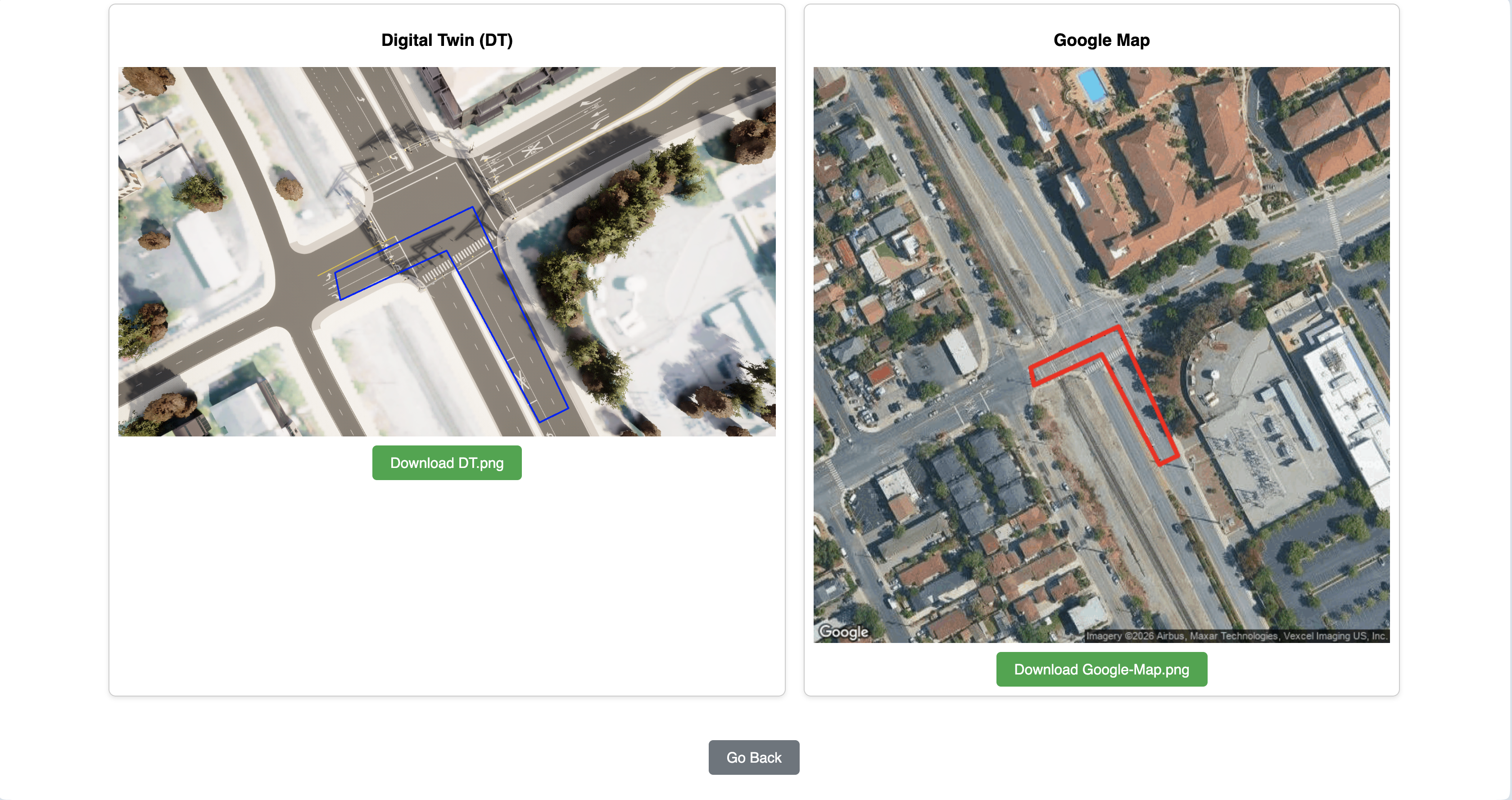
The Digital Twin Geo-Validator is a utility designed to check the geometric accuracy and georeferencing fidelity of a simulated environment’s road network against real-world geographic data. It specifically validates the critical transformation pipeline that converts local, simulated coordinates (from CARLA) into globally recognized geographic coordinates (Latitude/Longitude). The Validator will produce two images: Google Map satellite view and Digital Twin camera view with the road segment/overlay to compare.
Steps:
Open
http://<HOST_IP>:8000.Fill out form values. For more about Form Values. Go to Geo-Validator Input section to see how to fill out the form.
Make sure to provide a Google Maps API key with permission to generate map.
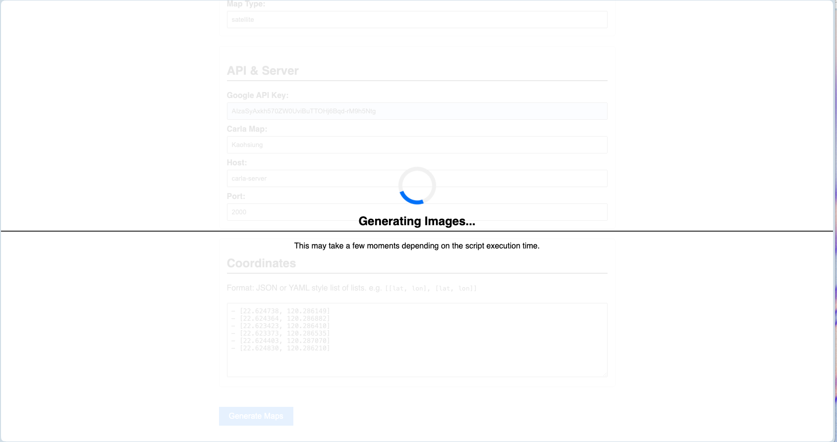
Once satisfied, click the Generate Maps button.
The system generates the Digital Twin frame and its corresponding real-world image.
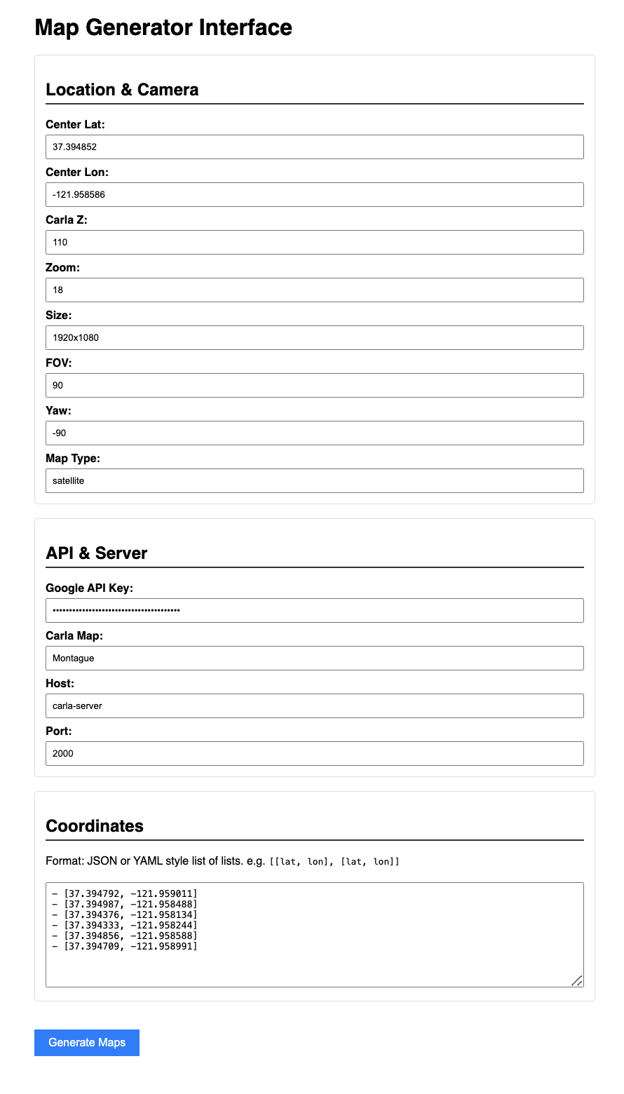
Geo-Validator Input#
The Geo-Validator Input form contains the fields required to generate satellite imagery of a specific area and its corresponding Digital Twin.
Center Lat / Center Lon
The precise GPS coordinates (Latitude and Longitude) that serve as the anchor point for your area of interest.

Carla Z
The altitude or vertical offset within the CARLA simulator environment. This ensures the digital assets align correctly with the ground elevation of the satellite map.

Zoom
Determines the magnification level of the satellite imagery. Higher values provide more detail but cover a smaller geographic footprint.

Size
The dimensions (in pixels) of the captured image or the simulated square area.

FOV (Field of View)
The angular extent of the "camera" view. A wider FOV captures more periphery but can introduce lens distortion.

Yaw
The horizontal rotation (heading) of the camera or the map orientation, in degrees (-180 to 180). Default is -90, Straight down.

Map Type
Specifies the visual style of the imagery (e.g., Satellite, Terrain, Hybrid, or Roadmap).


API & Server Configuration

Google API Key
Your unique authentication token required to fetch high-resolution imagery and metadata from Google Maps Platform.

Carla Map
The specific asset name or environment file within the CARLA simulator that matches your real-world location. This must be the custom map(Montague, ...) that you imported into the carla server.

Host
The IP address of the machine running the CARLA server (e.g., 127.0.0.1 for local or a specific server IP or carla-server(value you chose) as dns in your docker compose environment).

Port
The network port used for the carla server communication (default used by Carla Server is 2000).


Coordinates (Pathing/Boundaries)
This section defines specific points of interest or boundaries within your center-point radius. This is used to define a boundary polygon for your ROI to validate.
Those values can be retrieved using google map UI. Simply click on a point on the map and record the geo coordinate.
Check out this sample Montague Polygon:
- [37.388607, -121.954568]
- [37.388851, -121.954069]
- [37.38877, -121.953662]
- [37.38838, -121.954091]
- [37.388467, -121.954463]
Image Calibrator API#
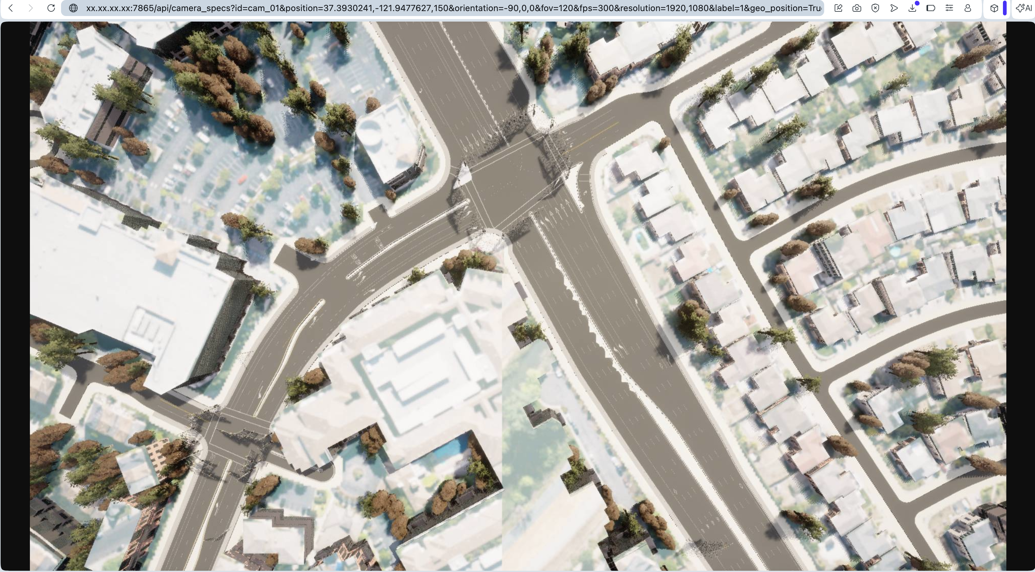
Having the Image Calibrator API available is extremely useful, particularly in the fields of autonomous systems, simulation, and AI training. The API allows developers to quickly generate realistic, calibrated synthetic images from the Digital Twin given camera parameters. This API is intended for use only with custom maps that include valid geographic references. Built-in CARLA maps (such as Town01, Town02, etc.), which use fictional coordinate systems, are not supported by this API. the following steps explain the structure of a request. All required configuration options are passed as query parameters in the URI, as shown in the example below
URI Parameter Details
<HOST_IP>:7865
Specifies the host IP address and port where the API service is running.

/api/camera_specs
The API endpoint used to define or retrieve camera specifications.

id=cam_01
A unique identifier for the camera.

position=22.623365,120.283904,150
The camera's position, expressed as a comma-separated list of coordinates (e.g., latitude, longitude, and altitude).

orientation=-90,0,0
The camera's orientation in degrees, typically representing pitch, yaw, and roll.

fov=120
The camera's field of view in degrees.

fps=30
The frame rate of the camera in frames per second.

resolution=1920,1080
The camera's output resolution, specified as width and height in pixels.

label=1
A numeric label or category identifier associated with the camera.

geo_position=True
Indicates whether the provided position values should be interpreted as geographic coordinates.

map_name=Kaohsiung
The name of the map or environment in which the camera is deployed.
Steps:
Call the API with your camera specs as shown below.
http://<HOST_IP>:7865/api/camera_specs?id=cam_01&position=37.3930241,-121.9477627,150&orientation=-90,0,0&fov=120&fps=300&resolution=1920,1080&label=1&geo_position=True&map_name=Montague
Stoping Your Deployment#
docker compose --profile dt_based_calibration down