


cuMAC Developer Guide#
cuMAC Software Architecture#
The architecture for offloading MAC scheduler functions to the GPU is illustrated in the following figure:
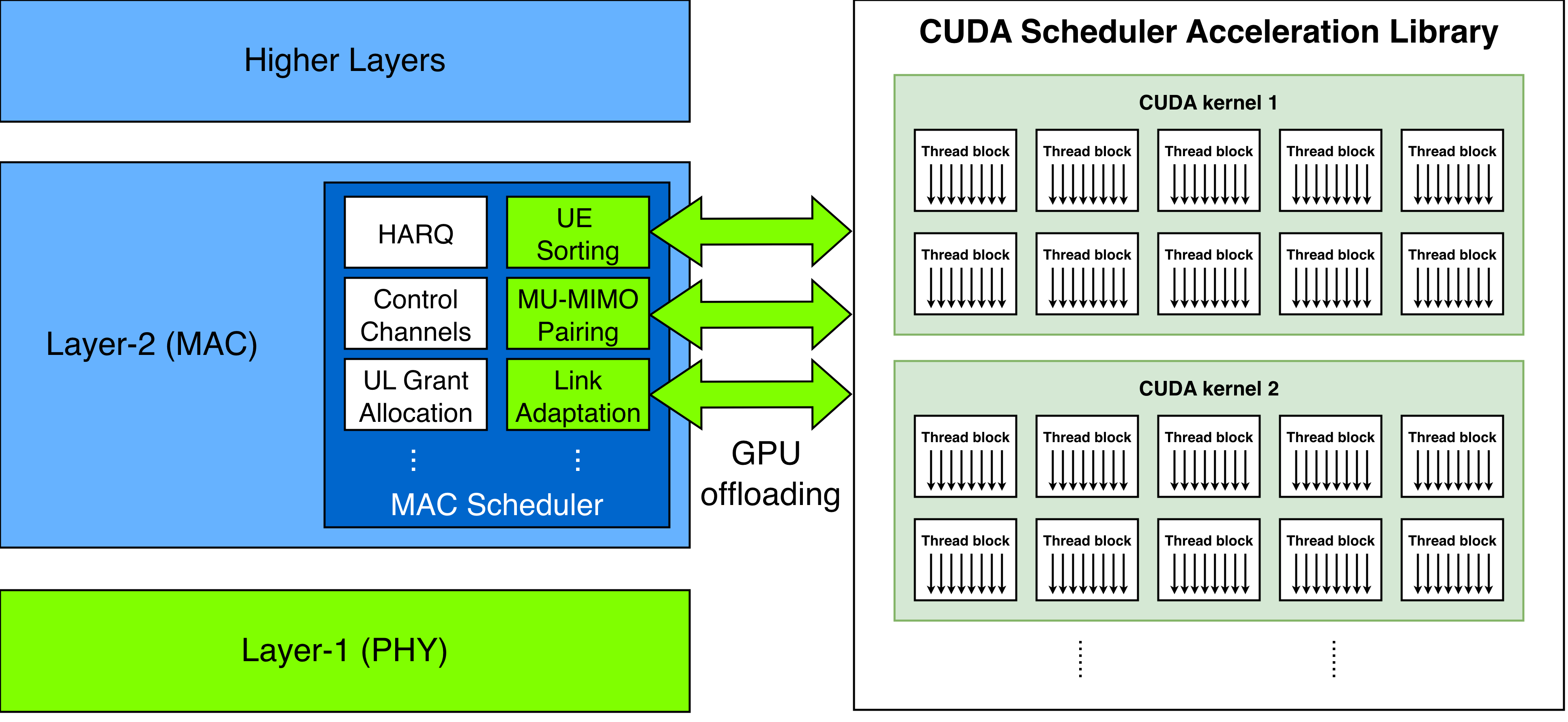
GPU offloading for MAC scheduler functions
The L2 stack host, which contains the MAC scheduler, operates on the CPU.
Compute-intensive MAC scheduling functions are offloaded to the GPU for accelerated processing and improved spectral efficiency.
The cuMAC architecture including the GPU offloading APIs, cuMAC-CP interface, and the CUDA-based MAC scheduling algorithm library is illustrated in the following figure:
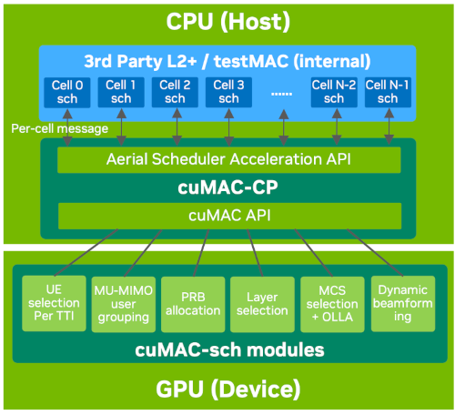
cuMAC architecture
Aerial Scheduler Acceleration API - A set of APIs provided by cuMAC-CP to interface with the L2 stack host for offloading MAC scheduling functions to the GPU.
cuMAC-CP — The control-plane process that interfaces between the L2 stack host and the MAC scheduling functions running on the GPU.
cuMAC-Sch API - A set of APIs called by cuMAC-CP to launch the CUDA-based MAC scheduling algorithms on the GPU.
cuMAC Algorithm CUDA Library - The library of CUDA implementations with C++ wrappers of the MAC scheduling algorithms.
Implementation Details#
Multi-cell scheduling - All cuMAC scheduling algorithms are implemented as CUDA kernels that are executed by GPU and jointly compute the scheduling solutions (PRB allocation, MCS selection, layer selection, etc.) for a group of cells at the same time. The algorithms can be constrained to single cell scheduling by configuring a single cell in the cell group. A comparison between the single-cell scheduler and multi-cell scheduler approaches is given in the below figure.
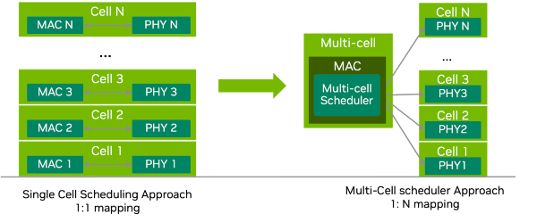
Single-cell scheduler approach vs. multi-cell scheduler approach#
Scheduling algorithm CUDA implementation
PF (Proportional Fairness) UE down-selection algorithm - cuMAC offers a PF-based UE selection algorithm to down-select a subset of UEs for new transmissions or HARQ re-transmissions in each TTI from the pool of all active UEs in each cell of a cell group. The association of UEs and cells in the cell group is an input to the UE selection module. When selecting UEs for each cell in each TTI, the UE selection algorithm first assigns a priority weight to each active UE in a cell and then sorts all active UEs in descending order of the priority weight. The subset of UEs that have the highest priority weights in each cell are selected for scheduling in a TTI. The number of selected UEs per cell is an input parameter to this module. HARQ re-transmissions are always assigned with the highest priority weight. For the new-transmission UEs, their priority weights are the PF metrics, calculated as the ratio of each UE’s long-term average throughput and its instantaneous achievable data rate. The UE selection algorithm is implemented as CUDA kernels that run on GPU and jointly select UEs for all cells in a cell group at the same time.
PF PRB allocation algorithms - cuMAC offers algorithms to perform channel-aware and frequency-selective PRB allocation among a group of cells and their connected active UEs on a per-TTI basis. The input arguments to the PRB allocation algorithms include the narrow-band SRS channel estimates (MIMO channel matrices) per cell-UE link, the association solutions between cells and UEs, and other UE status and cell group parameters. The output is the PRB allocation solution for the cell group, whose data format depends on the type of allocation: 1) for type-0 allocation, a per UE binary bitmap indicating whether each PRB is allocated to the UE, and 2) for type-1 allocation, with 2 elements per UE indicating the starting and ending PRB indices for the UE’s allocation. Two versions of the PRB allocation algorithms are provided, one for single cell scheduling and the other for multi-cell joint scheduling. A major difference between the two versions is that the multi-cell algorithm considers the impact of inter-cell interference in the evaluation of per-PRB SINRs, which can be derived from the narrow-band SRS channel estimates. The single-cell version does not explicitly consider inter-cell interference and only utilizes information restricted to each individual cell. The multi-cell algorithm can lead to a globally optimized resource allocation in a cell group by leveraging all available information from the coordinated multiple cells. A prototyping CUDA kernel implementation of PRB allocation algorithms is provided in the figure below.
Layer selection algorithm - cuMAC offers layer selection algorithms that choose the best set of layers for transmission for a UE based on the singular value distribution across the UE’s multiple layers. A predetermined singular value threshold is used to find the number of layers (with descending singular values) that can be supported on each subband (PRB group). Then the minimum number of layers across all allocated subbands to the UE is chosen as the optimal layer selection solution. Input arguments to the layer selection algorithms include the PRB allocation solution per UE, the singular values of each UE’s channel on its allocated subbands, the association solutions between cells and UEs, and other UE status and cell group parameters. The output is the per-UE layer selection solution. The layer selection algorithm is implemented as CUDA kernels that run on GPU and jointly select layers for all UEs in a cell group at the same time.
MCS selection algorithm - cuMAC offers MCS selection algorithms that choose the best feasible MCS (highest level that can meet a given BLER target) per UE based on a given PRB allocation solution. An outer-loop link adaptation algorithm is integrated internally to the MCS selection algorithm, which offsets the SINR estimates based on previous transport block decoding results per UE link. Input arguments to the MCS selection algorithms include the PRB allocation solution per UE, the narrow-band SRS channel estimates (MIMO channel matrices) per cell-UE link, the association solutions between cells and UEs, the decoding results of the last transport block for each UE, and other UE status and cell group parameters. The output is the per-UE MCS selection solution. The MCS selection algorithm is implemented as CUDA kernels that run on GPU and jointly select MCS for all UEs in a cell group at the same time.
64T64R MU-MIMO scheduling - cuMAC has a CUDA-based implementation of 64T64R MU-MIMO scheduler that consists of three components: 1) UE sorting, 2) MU-MIMO UE grouping and 3) MCS selection. The UE sorting module sorts all active UEs in each cell considering the proportional-fairness (PF) metric per UE, the feasibility for MU-MIMO transmission (based on a threshold for the SRS wideband SNR), and the HARQ re-transmission status of each UE. The UE grouping module uses a channel semi-orthogonality-based algorithm to determine the candidate MU-MIMO UE groups for each cell based on the SRS channel estimates, selects the UEs/UE groups for the current TTI, and allocates PRBs to the selected UEs/UE groups. The MCS selection for each selected UE is done using the SINR-to-MCS mapping table with calibrations from the OLLA algorithm and computed beamforming gains.
CPU reference code - CPU C++ implementation of the above algorithms is also provided for verification and performance evaluation purposes.
cuMAC Testing#
4T4R Scheduler Performance Test#
cuMAC contains a testbench (/opt/nvidia/cuBB/cuMAC/examples/multiCellSchedulerUeSelection) for performing
simplified system-level simulations to evaluate the performance of the 4T4R scheduler algorithm implementations.
For each simulation, the testbench runs for a given number of contiguous time slots, and in each slot executes scheduling algorithms sequentially in the following order:
UE selection > PRG allocation > layer selection > MCS selection.
The parameter setup for the simulation is configured using the file /opt/nvidia/cuBB/cuMAC/examples/parameters.h.
Parameters like the simulation duration numSimChnRlz, the number of cells numCellConst, and the number of gNB/UE antennas nBsAntConst / nUeAntConst,
among others, can be adjusted in this file to meet the specific simulation requirements.
KPIs such as the sum cell throughput, per-UE throughput, and proportional fairness metrics can be obtained from the simulations for analyzing the scheduler algorithms’ performance.
This testbench supports running different 4T4R scheduler algorithms on GPU and CPU, e.g., a multi-cell scheduler running on GPU versus a single-cell scheduler running on CPU.
It enables the comparison of different algorithms’ performance through a single simulation run.
An example figure with the cell sum throughput curves of the multi-cell and single-cell schedulers is provided below:
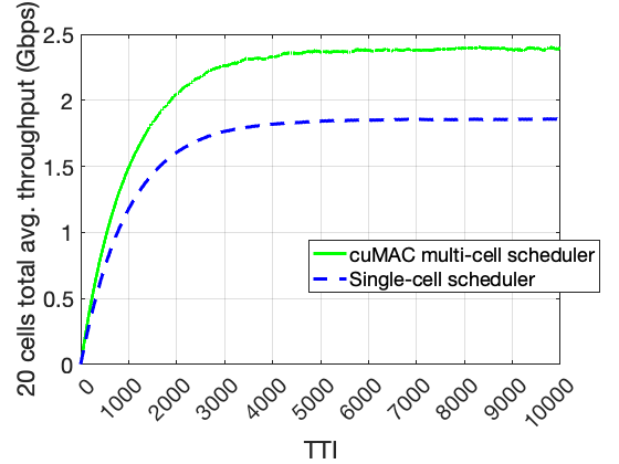
Cell sum throughput curves comparison: multi-cell scheduler vs. single-cell scheduler#
This testbench can be also used to validate the GPU/CUDA algorithm implementations against the CPU C++ versions of the same algorithm. This can be done by configuring the same scheduler algorithm for both GPU and CPU in the simulation. At the end of the simulation, the gaps between the GPU and CPU performance curves are evaluated. The testbench returns 0 (success) if the performance curve gaps are less than the tolerance threshold; otherwise, it returns 1 (failure).
After building cuMAC, use the following command to check input arguments of the testbench:
./opt/nvidia/cuBB/build/cuMAC/examples/multiCellSchedulerUeSelection/multiCellSchedulerUeSelection -h
The testbench currently supports three channel models in the system simulations: a time-correlated Rayleigh fading model, a GPU-accelerated TDL channel model, and a GPU-accelerated CDL channel model.
Use the input argument -f <0/1/2/3/4> to specify the desired channel model:
-f 0for Rayleigh fading-f 1for TDL channel model with CFR on PRBG-f 2for TDL channel model with CFR on PRBG and SC-f 3for CDL channel model with CFR on PRBG-f 4for CDL channel model with CFR on PRBG and SC
Note that currently only CFR on PRBG is used in cuMAC scheduler. It’s recommended to use -f <0/1/3> for the system simulation. The use of -f <2/4> is reserved for future developments. Since the data volume of CFR on SC is much larger than that of CFR on PRBG, it will cost additional GPU memory.
To run system simulation with the DL/UL scheduler pipeline:
Configure simulation parameters in the
/opt/nvidia/cuBB/cuMAC/examples/parameters.hfile.Build cuMAC within the cuBB container.
Run simulation with the DL/UL scheduler pipeline:
./opt/nvidia/cuBB/build/cuMAC/examples/multiCellSchedulerUeSelection/multiCellSchedulerUeSelection -d [0 or 1 for DL/UL] -f [0/1/2/3/4 for channel model] -b [0 or 1 for CPU algorithm choice] -p [0 or 1 for FP32/FP16 on GPU]
Passing criteria:
Performance curves achieved by GPU and CPU scheduler implementations should match: testbench returns 0 (PASS) or 1 (FAIL)
Two types of performance curves are considered:
Sum throughput of all cells
CDF of per-UE throughput
cuMAC Test Vector Generation#
cuMAC supports the generation of HDF5 test vectors using the multiCellSchedulerUeSelection system simulation testbench.
Each test vector contains parameters and data arrays defined in the cuMAC API structures (/opt/nvidia/cuBB/cuMAC/src/api.h):
cumacCellGrpUeStatus, cumacCellGrpPrms, and cumacSchdSol.
When a simulation with the testbench is completed (after a configured number of time slots), a HDF5 test vector file is created, with data collected from the last simulated slot.
A number of pre-generated test vectors are located in the /opt/nvidia/cuBB/cuMAC/testVectors directory.
To enable the test vector generation, use the input argument -t 1 with the multiCellSchedulerUeSelection testbench along with other input arguments.
For example:
Generate a DL test vector:
./opt/nvidia/cuBB/build/cuMAC/examples/multiCellSchedulerUeSelection/multiCellSchedulerUeSelection -t 1
Generate a UL test vector:
./opt/nvidia/cuBB/build/cuMAC/examples/multiCellSchedulerUeSelection/multiCellSchedulerUeSelection -d 0 -t 1
Test Vector Loading Test#
cuMAC has a testbench (/opt/nvidia/cuBB/cuMAC/examples/tvLoadingTest) to load pre-generated HDF5 test vectors and call the DL/UL scheduler modules/pipeline to compute scheduling solutions based on the input data contained in the test vector.
This testbench can be used to verify the implementation correctness of GPU/CUDA scheduler algorithms by comparing the solutions computed from both GPU and CPU versions of the same algorithms.
Basically, given the same input data from a test vector, GPU and CPU
implementations of the same scheduler algorithms should produce the same
output solution.
Two types of tests are supported:
Per DL/UL scheduler module test: UE selection, PRG allocation, layer selection, and MCS selection
Complete DL/UL scheduler pipeline test
After building cumac, use the following command to check input arguments of the testbench:
./opt/nvidia/cuBB/build/cuMAC/examples/tvLoadingTest/tvLoadingTest -h
Per scheduler module tests:
DL UE selection:
./opt/nvidia/cuBB/build/cuMAC/examples/tvLoadingTest/tvLoadingTest -i [path to TV] -g 2 -d 1 -m 01000
DL PRG allocation:
./opt/nvidia/cuBB/build/cuMAC/examples/tvLoadingTest/tvLoadingTest -i [path to TV] -g 2 -d 1 -m 00100
DL layer selection:
./opt/nvidia/cuBB/build/cuMAC/examples/tvLoadingTest/tvLoadingTest -i [path to TV] -g 2 -d 1 -m 00010
DL MCS selection:
./opt/nvidia/cuBB/build/cuMAC/examples/tvLoadingTest/tvLoadingTest -i [path to TV] -g 2 -d 1 -m 00001
UL scheduler modules can be tested by setting input argument:
-d 0
Complete DL/UL scheduler pipeline tests
DL/UL scheduler modules executed sequentially: UE selection > PRG allocation > layer selection > MCS selection
DL scheduler pipeline:
./opt/nvidia/cuBB/build/cuMAC/examples/tvLoadingTest/tvLoadingTest -i [path to TV] -g 2 -d 1 -m 01111
UL scheduler pipeline:
./opt/nvidia/cuBB/build/cuMAC/examples/tvLoadingTest/tvLoadingTest -i [path to TV] -g 2 -d 0 -m 01111
Passing criteria:
Solutions computed by CPU and GPU should match exactly: testbench returns 0 (PASS) or 1 (FAIL)
DRL MCS Selection Test#
Aerial cuMAC introduced a new DRL-based MCS selection module that can be used
as part of the 4T4R multi-cell scheduler (to replace the basic OLLA algorithm for MCS selection).
A testbench designed for testing the DRL MCS selection module is available under /opt/nvidia/cuBB/cuMAC/examples/ml/drlMcsSelection.
Along with the testbench, there is a pre-trained neural network for MCS selection inference saved in a model.onnx file
under /opt/nvidia/cuBB/cuMAC/examples/ml/trainedModels and a number of pre-generated HDF5 test vectors under /opt/nvidia/cuBB/cuMAC/examples/ml/testVectors/drlMcsSelection.
To check all supported input arguments to this testbench, use the following command:
./opt/nvidia/cuBB/build/cuMAC/examples/ml/drlMcsSelection/drlMcsSelection -h.
For a test run of the testbench using the test vectors, use the following command: ./opt/nvidia/cuBB/build/cuMAC/examples/ml/drlMcsSelection/drlMcsSelection -i [path to /opt/nvidia/cuBB/cuMAC/examples/ml/testVectors/drlMcsSelection] -m [path to /opt/nvidia/cuBB/cuMAC/examples/ml/trainedModels/model.onnx] -g [GPU device index].
If the test passes, the following messages will be printed at the end of the program:
...

Test based on the provided HDF5 test vectors

=========================================
Event queue lengths: (UE 0, 49) (UE 1, 49) (UE 2, 49) (UE 3, 49) (UE 4, 49) (UE 5, 49)

=========================================
Start per time slot processing:
=========================================
Testing complete
PASSED!
For a test run without test vectors (using the default test scenario setup), use the following command: ./opt/nvidia/cuBB/build/cuMAC/examples/ml/drlMcsSelection/drlMcsSelection -m [path to /opt/nvidia/cuBB/cuMAC/examples/ml/trainedModels/model.onnx] -g [GPU device index].
If the test passes, the following messages will be printed at the end of the program:
...

=========================================
Event queue lengths: (UE 0, 61) (UE 1, 61) (UE 2, 61) (UE 3, 61) (UE 4, 61) (UE 5, 61)


=========================================
Start per time slot processing:
Slot #0 - selected MCS: (UE 0, 0) (UE 1, 0) (UE 2, 0) (UE 3, 0) (UE 4, 0) (UE 5, 0)
Slot #27 - selected MCS: (UE 0, 0) (UE 1, 0) (UE 2, 0) (UE 3, 0) (UE 4, 0) (UE 5, 0)
Slot #56 - selected MCS: (UE 0, 3) (UE 1, 0) (UE 2, 1) (UE 3, 2) (UE 4, 3) (UE 5, 0)

...
=========================================
Testing complete
PASSED!
64T64R MU-MIMO Scheduler Test#
A testbench for the cuMAC CUDA-based 64T64R MU-MIMO scheduler implementation is available under /opt/nvidia/cuBB/cuMAC/examples/multiCellMuMimoScheduler.
This testbench is used to verify the correctness of MU-MIMO scheduling solutions computed by the cuMAC 64T64R MU-MIMO scheduler implementation.
To check input arguments of this testbench, use the following command:
./opt/nvidia/cuBB/build/cuMAC/examples/multiCellMuMimoScheduler/multiCellMuMimoScheduler -h.
(Note: The input argument -a is currently not supported.)
This testbench currently supports testing using either a simple Rayleigh fading channel model or a GPU-accelerated 3GPP 38.901 channel model.
To perform a test run, follow the steps below:
Build cuMAC within the cuBB container.
Configure test parameters in the following YAML file:
/opt/nvidia/cuBB/cuMAC/examples/multiCellMuMimoScheduler/config.yaml.Run the MU-MIMO scheduler test using the following command:
./opt/nvidia/cuBB/build/cuMAC/examples/multiCellMuMimoScheduler/multiCellMuMimoScheduler.
When a test passes, logging output similar to the following will be displayed:
cuMAC 64T64R MU-MIMO scheduler pipeline test: Running on GPU device 0 (total devices: 1)
Successfully loaded channel configuration: fading_type = 1
Loaded config parameters
Setup channel: Using SLS channel model with embedded configuration
SLS channel model initialized successfully with embedded configuration
UE sorting setup executed
UE grouping setup executed
Beamforming setup executed
MCS selection setup executed
UE sorting run executed
UE grouping run executed
Beamforming run executed
MCS selection run executed
Cell #0: 2 UE groups scheduled
   UE group #0: 8 UEs, startPrg = 0, endPrg = 35, total number of layers = 16
      UE IDs: 0 1 2 3 4 5 6 7
      MCS: 0 0 0 0 0 0 0 0
      Number of layers: 2 2 2 2 2 2 2 2
      nSCID: 0 0 0 0 1 1 1 1
   UE group #1: 8 UEs, startPrg = 36, endPrg = 67, total number of layers = 16
      UE IDs: 8 9 10 11 12 13 14 15
      MCS: 0 0 0 0 0 0 0 0
      Number of layers: 2 2 2 2 2 2 2 2
      nSCID: 0 0 0 0 1 1 1 1
Cell #1: 2 UE groups scheduled
   UE group #0: 8 UEs, startPrg = 0, endPrg = 35, total number of layers = 16
      UE IDs: 64 65 66 67 68 69 70 71
      MCS: 0 0 0 0 0 0 0 0
      Number of layers: 2 2 2 2 2 2 2 2
      nSCID: 0 0 0 0 1 1 1 1
   UE group #1: 8 UEs, startPrg = 36, endPrg = 67, total number of layers = 16
      UE IDs: 72 73 74 75 76 77 78 79
      MCS: 0 0 0 0 0 0 0 0
      Number of layers: 2 2 2 2 2 2 2 2
      nSCID: 0 0 0 0 1 1 1 1
Cell #2: 2 UE groups scheduled
   UE group #0: 8 UEs, startPrg = 0, endPrg = 35, total number of layers = 16
      UE IDs: 128 129 130 131 132 133 134 135
      MCS: 0 0 0 0 0 0 0 0
      Number of layers: 2 2 2 2 2 2 2 2
      nSCID: 0 0 0 0 1 1 1 1
   UE group #1: 8 UEs, startPrg = 36, endPrg = 67, total number of layers = 16
      UE IDs: 136 137 138 139 140 141 142 143
      MCS: 0 0 0 0 0 0 0 0
      Number of layers: 2 2 2 2 2 2 2 2
      nSCID: 0 0 0 0 1 1 1 1
Cell #3: 2 UE groups scheduled
   UE group #0: 8 UEs, startPrg = 0, endPrg = 35, total number of layers = 16
      UE IDs: 192 193 194 195 196 197 198 199
      MCS: 0 0 0 0 0 0 0 0
      Number of layers: 2 2 2 2 2 2 2 2
      nSCID: 0 0 0 0 1 1 1 1
   UE group #1: 8 UEs, startPrg = 36, endPrg = 67, total number of layers = 16
      UE IDs: 200 201 202 203 204 205 206 207
      MCS: 0 0 0 0 0 0 0 0
      Number of layers: 2 2 2 2 2 2 2 2
      nSCID: 0 0 0 0 1 1 1 1
Cell #4: 2 UE groups scheduled
   UE group #0: 8 UEs, startPrg = 0, endPrg = 35, total number of layers = 16
      UE IDs: 256 257 258 259 260 261 262 263
      MCS: 0 0 0 0 0 0 0 0
      Number of layers: 2 2 2 2 2 2 2 2
      nSCID: 0 0 0 0 1 1 1 1
   UE group #1: 8 UEs, startPrg = 36, endPrg = 67, total number of layers = 16
      UE IDs: 264 265 266 267 268 269 270 271
      MCS: 0 0 0 0 0 0 0 0
      Number of layers: 2 2 2 2 2 2 2 2
      nSCID: 0 0 0 0 1 1 1 1
Cell #5: 2 UE groups scheduled
   UE group #0: 8 UEs, startPrg = 0, endPrg = 35, total number of layers = 16
      UE IDs: 320 321 322 323 324 325 326 327
      MCS: 0 0 0 0 0 0 0 0
      Number of layers: 2 2 2 2 2 2 2 2
      nSCID: 0 0 0 0 1 1 1 1
   UE group #1: 8 UEs, startPrg = 36, endPrg = 67, total number of layers = 16
      UE IDs: 328 329 330 331 332 333 334 335
      MCS: 0 0 0 0 0 0 0 0
      Number of layers: 2 2 2 2 2 2 2 2
      nSCID: 0 0 0 0 1 1 1 1
Summary - cuMAC multi-cell MU-MIMO scheduler simulation test: PASS
When the testbench returns, the computed MU-MIMO scheduling solutions are saved in a result HDF5 file, e.g., under default configuration, TV_cumac_result_64T64R_6PC_DL.h5.
cuMAC-CP Tests#
Basic cuMAC-CP Standalone Test#
This section describes how to run the TestMAC + cuMAC-CP standalone test.
Configuration Files#
cumac_cp.yaml#
Configure cell number and CPU core assignments for cuMAC-CP:
# CPU core shared by all low-priority threads
low_priority_core: 19

recv_thread_config:
  name: cumac_cp_recv
  cpu_affinity: 25
  sched_priority: 95

# cuMAC task worker cores
worker_cores: [31, 32, 33, 34, 35, 36, 37, 38]

# Total cell number
cell_num: 8
test_cumac_config.yaml#
Configure cuMAC settings and CPU cores for testMAC:
recv_thread_config:
  name: cumac_recv
  cpu_affinity: 43
  sched_priority: 95

sched_thread_config:
  name: cumac_sched
  cpu_affinity: 39
  sched_priority: 96

builder_thread_config:
  name: cumac_builder
  cpu_affinity: 39
  sched_priority: 95

# Worker thread cores, can be used for both outgoing message building and incoming message handling
worker_cores: [26, 27, 28, 29]

# Run test_mac + cumac_cp only without depending on L1
cumac_cp_standalone: 1
test_mac_config.yaml#
Enable cuMAC-CP test configuration:
# Set to yaml file like test_cumac_config.yaml to enable cuMAC-CP test
test_cumac_config_file: test_cumac_config.yaml
Test Execution#
Generate Test Vectors for the first four modules#
Configure proper parameters per requirements. Below is an example test for 8 cells.
cd $cuBB_SDK
sed -i 's/#define numCellConst[ ]*.*/#define numCellConst 8/g' cuMAC/examples/parameters.h
sed -i 's/#define gpuDeviceIdx[ ]*.*/#define gpuDeviceIdx 0/g' cuMAC/examples/parameters.h
sed -i 's/#define cpuGpuPerfGapSumRConst[ ]*.*/#define cpuGpuPerfGapSumRConst 0.03/g' cuMAC/examples/parameters.h
sed -i 's/#define cpuGpuPerfGapPerUeConst[ ]*.*/#define cpuGpuPerfGapPerUeConst 0.01/g' cuMAC/examples/parameters.h
sed -i 's/#define gpuAllocTypeConst[ ]*.*/#define gpuAllocTypeConst 0/g' cuMAC/examples/parameters.h
sed -i 's/#define cpuAllocTypeConst[ ]*.*/#define cpuAllocTypeConst 0/g' cuMAC/examples/parameters.h
Generate per cell and per group TVs for cuMAC-CP:
mkdir $cuBB_SDK/testVectors/cumac
cd $cuBB_SDK/testVectors/cumac
sudo $cuBB_SDK/build/cuMAC/examples/multiCellSchedulerUeSelection/multiCellSchedulerUeSelection -t 3
Generate Test Vectors for the pfmSort module#
Configure proper parameters per requirements. Below is an example test for 8 cells.
cd $cuBB_SDK
sed -i 's/NUM_CELL:[ ]*.*/NUM_CELL: 8/g' cuMAC/examples/pfmSort/config.yaml
Generate TV for pfmSort:
cd $cuBB_SDK/testVectors/cumac
sudo $cuBB_SDK/build/cuMAC/examples/pfmSort/pfmSortTest -t 2
Run the Tests#
Configurations#
Below is an example to enable all modules for 8 cells.
Configure cell number in cuMAC-CP config file.
# cuMAC-CP/config/cumac_cp.yaml

cell_num: 8 # Set to the number of cells
Configure cell number in testMAC and configure task_bitmask in testMAC config file to select the cuMAC modules.
# cuPHY-CP/testMAC/testMAC/test_cumac_config.yaml

cumac_cell_num: 8 # Set to the number of cells

# CUMAC task bitmask:
# b0 - multiCellUeSelection;
# b1 - multiCellScheduler;
# b2 - multiCellLayerSel;
# b3 - mcsSelectionLUT;
# b4 - pfmSort;
task_bitmask: 0x1F # Enable all modules
Note
Since the first four modules have sequential dependencies, the valid task_bitmask values are:
0x1, 0x3, 0x7, 0xF, 0x11, 0x13, 0x17, 0x1F
Execute the tests in the following order:
# 1. Run cumac_cp
sudo $cuBB_SDK/build/cuMAC-CP/cumac_cp

# 2. Run test_mac
sudo $cuBB_SDK/build/cuPHY-CP/testMAC/testMAC/test_mac F08 8C_60c
Expected Output#
cumac_cp Output#
Example console output:
16:11:36.999875 WRN 27518 0 25 [CUMCP.HANDLER] Cell 0 | CUMAC 2000 | ERR 0 | Slots 4000
16:11:36.999876 WRN 27518 0 25 [CUMCP.HANDLER] Cell 1 | CUMAC 2000 | ERR 0 | Slots 4000
16:11:36.999877 WRN 27518 0 25 [CUMCP.HANDLER] Cell 2 | CUMAC 2000 | ERR 0 | Slots 4000
16:11:36.999877 WRN 27518 0 25 [CUMCP.HANDLER] Cell 3 | CUMAC 2000 | ERR 0 | Slots 4000
16:11:36.999877 WRN 27518 0 25 [CUMCP.HANDLER] Cell 4 | CUMAC 2000 | ERR 0 | Slots 4000
16:11:36.999877 WRN 27518 0 25 [CUMCP.HANDLER] Cell 5 | CUMAC 2000 | ERR 0 | Slots 4000
16:11:36.999877 WRN 27518 0 25 [CUMCP.HANDLER] Cell 6 | CUMAC 2000 | ERR 0 | Slots 4000
16:11:36.999877 WRN 27518 0 25 [CUMCP.HANDLER] Cell 7 | CUMAC 2000 | ERR 0 | Slots 4000
test_mac Output#
Example console output for all modules enabled:
13:46:55.000020 CON 31866 0 [CUMAC.HANDLER] Cell  0 | CUMAC 2000 | UE_SEL 2000 | PRB_ALLOC 2000 | LAYER_SEL 2000 | MCS_SEL 2000 | PFM_SORT 2000 | ERR    0 | INV    0 | Slots 4000
13:46:55.000021 CON 31866 0 [CUMAC.HANDLER] Cell  1 | CUMAC 2000 | UE_SEL 2000 | PRB_ALLOC 2000 | LAYER_SEL 2000 | MCS_SEL 2000 | PFM_SORT 2000 | ERR    0 | INV    0 | Slots 4000
13:46:55.000022 CON 31866 0 [CUMAC.HANDLER] Cell  2 | CUMAC 2000 | UE_SEL 2000 | PRB_ALLOC 2000 | LAYER_SEL 2000 | MCS_SEL 2000 | PFM_SORT 2000 | ERR    0 | INV    0 | Slots 4000
13:46:55.000023 CON 31866 0 [CUMAC.HANDLER] Cell  3 | CUMAC 2000 | UE_SEL 2000 | PRB_ALLOC 2000 | LAYER_SEL 2000 | MCS_SEL 2000 | PFM_SORT 2000 | ERR    0 | INV    0 | Slots 4000
13:46:55.000023 CON 31866 0 [CUMAC.HANDLER] Cell  4 | CUMAC 2000 | UE_SEL 2000 | PRB_ALLOC 2000 | LAYER_SEL 2000 | MCS_SEL 2000 | PFM_SORT 2000 | ERR    0 | INV    0 | Slots 4000
13:46:55.000024 CON 31866 0 [CUMAC.HANDLER] Cell  5 | CUMAC 2000 | UE_SEL 2000 | PRB_ALLOC 2000 | LAYER_SEL 2000 | MCS_SEL 2000 | PFM_SORT 2000 | ERR    0 | INV    0 | Slots 4000
13:46:55.000025 CON 31866 0 [CUMAC.HANDLER] Cell  6 | CUMAC 2000 | UE_SEL 2000 | PRB_ALLOC 2000 | LAYER_SEL 2000 | MCS_SEL 2000 | PFM_SORT 2000 | ERR    0 | INV    0 | Slots 4000
13:46:55.000025 CON 31866 0 [CUMAC.HANDLER] Cell  7 | CUMAC 2000 | UE_SEL 2000 | PRB_ALLOC 2000 | LAYER_SEL 2000 | MCS_SEL 2000 | PFM_SORT 2000 | ERR    0 | INV    0 | Slots 4000
cuMAC-CP + cuBB Test#
This section describes how to run the cuMAC-CP (cumac_cp) + cuBB (test_mac + cuphycontroller_scf + ru_emulator) test.
Refer to the Running cuBB End-to-End section for cuBB test instructions.
For cuMAC-CP part, follow about cuMAC-CP standalone test instructions but have below differences:
Configure cumac_cp_standalone to 0#
# Run cumac_cp + cuBB (test_mac + cuphycontroller_scf + ru_emulator) tests
cumac_cp_standalone: 0
Enable MPS#
Since cumac_cp and cuphycontroller_scf both use the same GPU, MPS need to be enabled for both of them.
First, start the MPS server.
# Export MPS variables
export CUDA_DEVICE_MAX_CONNECTIONS=8
export CUDA_MPS_PIPE_DIRECTORY=/var
export CUDA_MPS_LOG_DIRECTORY=/var

# Stop existing MPS
sudo -E echo quit | sudo -E nvidia-cuda-mps-control

# Start MPS
sudo -E nvidia-cuda-mps-control -d
sudo -E echo start_server -uid 0 | sudo -E nvidia-cuda-mps-control
Then, export the MPS variables for cumac_cp and cuphycontroller_scf before running them.
# Export variables
export CUDA_DEVICE_MAX_CONNECTIONS=8
export CUDA_MPS_PIPE_DIRECTORY=/var
export CUDA_MPS_LOG_DIRECTORY=/var
Additional Configuration Options#
Debug Options#
Buffer dumping can be enabled in cuMAC-CP via debug_option. Note that this will impact timing and performance, so use only during debugging.