BlurFilterROI#
Overview#
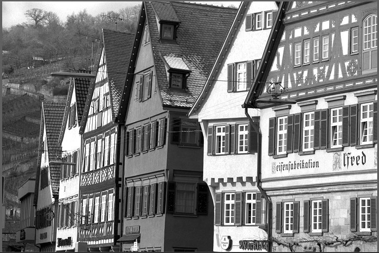
The BlurFilterROI operator performs a blur filter operation on specified regions of interest (ROI) in an image.
Input Image |
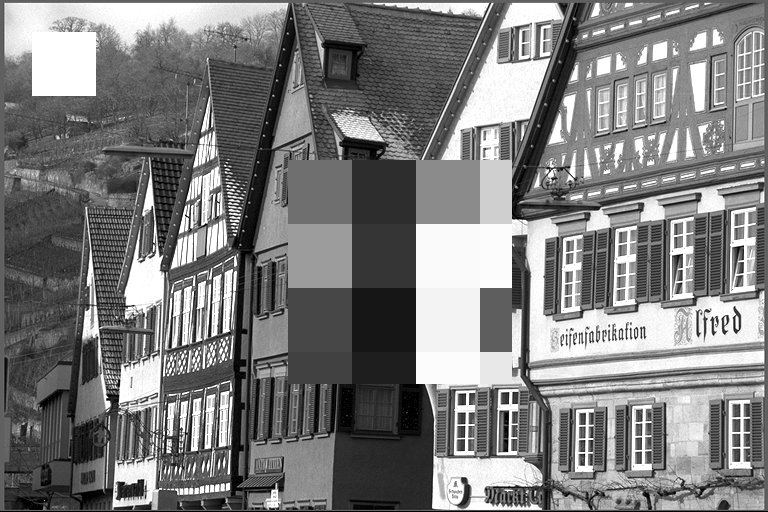
Output Image |
|---|---|
|
|
Algorithm Description#
The operator processes each ROI rectangle by dividing it into blocks and applies a blur effect by filling each block based on the pixel value at the top-left corner of the block. If two ROI rectangles are overlapped, the later ROI rectangle will overwrite the common part with the previous one in the input ROI rectangle list. Figure 1 shows the pixel value in the original image. Figure 2 shows in the case of a 4x3 ROI rectangle with block size 2x2, the ROI rectangle is divided into 4 blocks. Figure 3 shows in the case of 2 overlapped ROI rectangles, the later ROI rectangle overwrites the common part with the previous one.
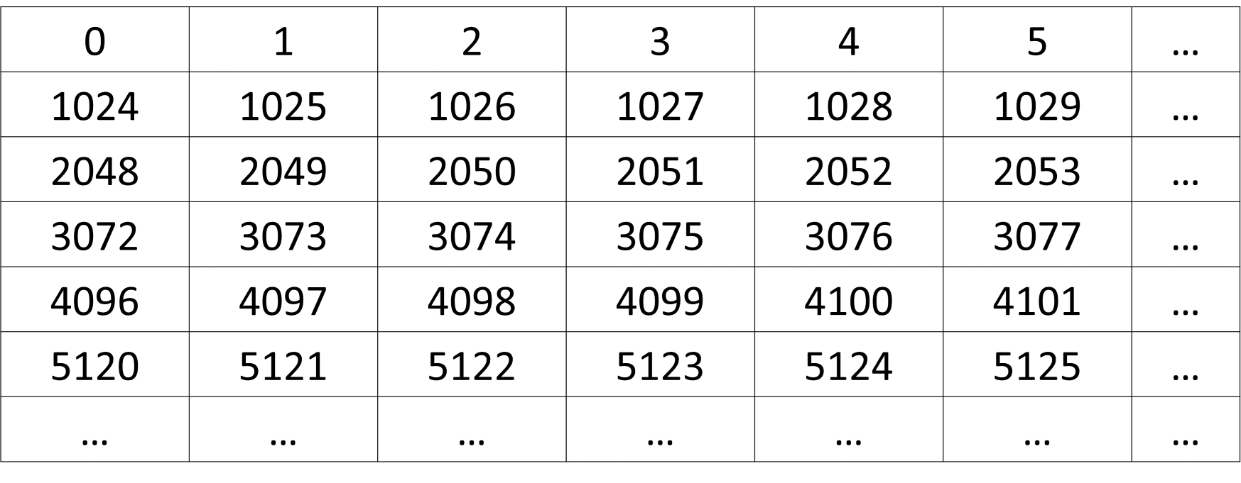
Figure 1: Original image.#
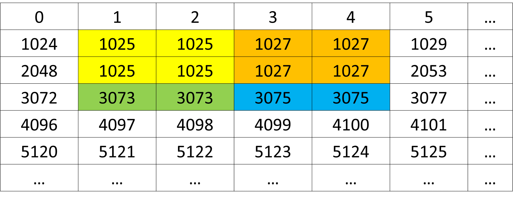
Figure 2: 4x3 ROI rectangle with block size 2x2.#
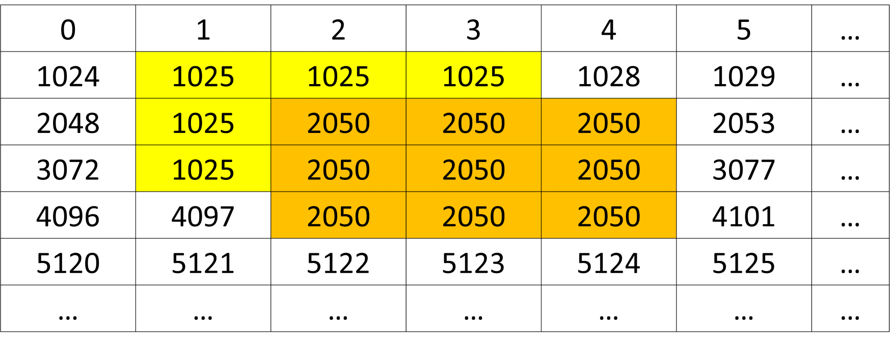
Figure 3: Overlapped ROI rectangles.#
Key Features#
Supports NV12 and its variants (NV12_ER) for both input and output images.
Supports pitch linear and block linear layout for both input and output images.
Multiple ROI rectangles can be processed in a single operation.
Configurable block size for ROI rectangle processing.
Limitations#
Maximum ROI rectangle width and height: 256 pixels.
Maximum number of ROI rectangles: 256.
ROI rectangle is assumed inside the image. There is no checking or error handling due to the performance reason.
Implementation Details#
Dataflow Configuration#
Use N input and N output RDFs (RasterDataflow) to split the whole input/output image into tiles and transfer them between DRAM and VMEM one by one. N equals to the number of planes of the image format.
Use 1 SQDF (SequenceDataflow) to transfer the information (top-left coordinates, width and height) list of the ROI rectangles from DRAM to VMEM.
VMEM Buffer Allocation#
The following VMEM buffers are needed:
1 buffer to store the information (top-left coordinates, width and height) list of the ROI rectangles.
1 input buffer with double buffering to store the pixel value of each tiles reading from the input image.
1 output buffer with double buffering to store the pixel value of each tiles after the blur filter operation.
1 temporary data buffer to store the pixel value used for each block in the last block row when the processing of the ROI rectangle doesn’t finish in the current tile.
Solution Design#
The difficulty of this operator is how to handle the ROI rectangle which crosses the tiles, one solution is to set the tile width the same as the image width so that the cross behavior only happenes in the vertical direction. If the processing of the last block row of one ROI rectangle doesn’t finish in the current tile, the pixel value used for each block in the last block row will be written in a temporary data buffer to continue the processing in the beginning of the next tile.
The steps to process each ROI rectangle in one tile are listed as follows:
Calculate the height of the ROI rectangle in the current tile.
If the ROI rectangle doesn’t finish the processing in the previous tile, calculate the remaining height and continue the processing with the pixel value stored in the temporary data buffer and subtract the size from the total height.
Process the (remaining) height of the ROI rectangle. If the processing of the ROI rectangle doesn’t finish in the current tile, write the pixel value used for each block in the last block row in the temporary data buffer.
VPU Function Implementation#
The blur filter function processes each ROI rectangle in the following steps:
Divide the ROI rectangle into blocks according to the specified block size.
Read the pixel value from the top-left corner of each block or the temporary data buffer.
Write this value to all the pixels in the block with the vectorized instruction.
The blur filter function can be easily replaced according to the different blur requirements.
Performance#
Execution Time is the average time required to execute the operator on a single VPU core.
Note that each PVA contains two VPU cores, which can operate in parallel to process two streams simultaneously, or reduce execution time by approximately half by splitting the workload between the two cores.
Total Power represents the average total power consumed by the module when the operator is executed concurrently on both VPU cores.
For detailed information on interpreting the performance table below and understanding the benchmarking setup, see Performance Benchmark.
InFormat |
OutFormat |
NumRects |
RectSize |
BlockSize |
Execution Time |
Submit Latency |
Total Power |
|---|---|---|---|---|---|---|---|
NV12 |
NV12 |
1 |
256x256 |
16x16 |
0.254ms |
0.021ms |
14.705W |
NV12 |
NV12_BL |
1 |
256x256 |
16x16 |
0.263ms |
0.039ms |
14.222W |
NV12 |
NV12 |
1 |
1024x1024 |
16x16 |
0.427ms |
0.023ms |
12.642W |
NV12 |
NV12 |
1 |
1024x1024 |
32x32 |
0.296ms |
0.023ms |
14.122W |
NV12 |
NV12 |
2 |
1024x1024 |
32x32 |
0.420ms |
0.023ms |
13.034W |
NV12 |
NV12 |
128 |
64x64 |
16x16 |
0.587ms |
0.023ms |
11.757W |
NV12 |
NV12 |
256 |
64x64 |
16x16 |
1.007ms |
0.023ms |
10.874W |