MedianFilter#
Overview#
The median filter algorithm performs a two dimensional (2D) filter operation on the input image, replacing each pixel with the median value from its neighborhood defined by the 2D kernel.
Unlike linear filters like Gaussian blur or mean filter, the median filter preserves sharp edges while effectively removing noise, making it particularly valuable for various image processing applications. By replacing each pixel with the median value from its neighborhood rather than the mean, it’s much less sensitive to extreme values (outliers) than linear techniques.
Common applications of the median filter include impulse noise reduction, image smoothing, and pre-processing for computer vision algorithms.
Implementation#
In the current implementation, two border handling methods are supported: zero padding and clamp (border pixel extension). All supported image formats are: U8, Y8, Y8_ER, S8, U16, Y16, Y16_ER, S16, 2S16, U32 and S32.
Currently, only box kernel (all ones in the kernel window) of kernel sizes 3x3, 5x5, and 5x7 are supported. The 3x3 implementation is specially designed for the 3x3 box median filter. However, the algorithm for 5x5 and 5x7 can be easily extended to other kernel types and sizes.
Data Flow Configuration#
RasterDataFlow (RDF) is used for both input and output data flows.
The input RDF is configured with halo and circular buffer, to fetch pixels outside the tile and reuse overlapping pixels between tiles.
The output RDF is configured with ping-pong buffer, to parallelize the DMA and VPU workloads.
RDF tile sizes are set up as \(\text{TILE_W} = 128\), \(\text{TILE_H} = 128/\text{sizeof(T)}\), where \(\text{T}\) is the data type of the input image. The tile width is set to 128 to be divisible by vector lengths of all data types, to achieve maximal parallelism of vector instructions in the VPU kernel calculations. The tile height is set to be \(128/\text{sizeof(T)}\), so that the total tile size in bytes is \(128 \times 128/\text{sizeof(T)} * \text{sizeof(T)} = 16\text{KB}\), achieving full ADB/VDB efficiency.
When the input image size is not exactly a multiple of the tile size, RDF will automatically add padding to the last row/column tiles up to a full tile, and kernel functions will run on the padded tiles. Then the output data flow will only move out pixels within the valid region of the output image.
Border Handling#
The two supported border types can be directly realized by the two padding modes in RDF:
zero: PAD_CONST, padding by constant with value 0
clamp: PAD_BPE, padding by border pixel extension (BPE)
For input image format 2S16, simply applying padding by BPE will only copy the outer channel value, instead of padding the boundary pixel into channel-interleaved pattern as desired. To tackle this issue, the input RDF is configured with data type int32_t, regarding the 2 interleaved channels as a single int32_t value. Then padding by BPE results into correct channel-interleaved border values.
Kernel Processing#
The median filter is implemented by a two-pass approach. For each input tile, each pass iterates through all kernel windows, which are centered at output pixels in the tile (excluding halo pixels on the boundary), performing the following calculations:
1st pass: sort elements in each row of the kernel window, and store temporary sorted values.
2nd pass: load sorted rows in the kernel window from the 1st pass, and find the median value.
For 3x3 kernels, a specialized implementation is designed to find the median. For larger kernels (5x5, 5x7), a more general-purpose sorting network is employed.
3x3 Box Median Filter#
In the 1st pass, the 3 elements in each row are sorted. The minimum, middle and maximum values of the 3 elements are obtained by instructions vmin3/vmid3/vmax3.
In the 2nd pass, the median value turns out to be the middle value of 3 elements (middle is obtained by vmid3):
maximum of the minimum values in each row (obtained by vmax3)
minimum of the maximum values in each row (obtained by vmin3)
middle of the middle values in each row (obtained by vmid3)
Sorting Network#
For a general kernel, a sorting network is formed to find the median. The chosen sorting algorithm to generate the sorting network is odd-even merge sort.
Specifically, in the 1st pass, each row is sorted by odd-even merge sort. In the 2nd pass, the sorted rows are merged by odd-even merge recursively, until there is only one sorted array. Since we only need the median instead of the whole sorted array, the resulting sorting network is pruned to get rid of operations not related to finding the median.
The sorting network is implemented by a sequence of vsort2 instructions for pairwise comparisons.
Figures for the sorting network of the 1st and 2nd pass of the 5x5 kernel are shown below to illustrate the structure of the sorting network. The 1st pass sorting network is an application of the odd-even merge sort for 5 elements, which is non-typical because the number of elements is not a power of 2.
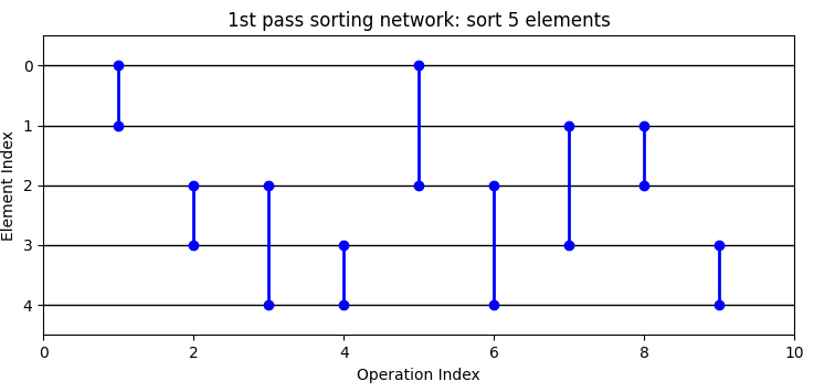
Figure 1: 5x5 median filter 1st pass sorting network.#
The 2nd pass sorting network merges the 5 sorted rows into one sorted array by applying the odd-even merge algorithm multiple times, each time merging two sorted arrays into one. The pruned operations are illustrated by red in the figure. It can be seen that the pruned operations are exactly the operations not affecting the median index. The full 2nd pass sorting network has 101 operations, of which 27 are pruned and 74 are kept to find the median.
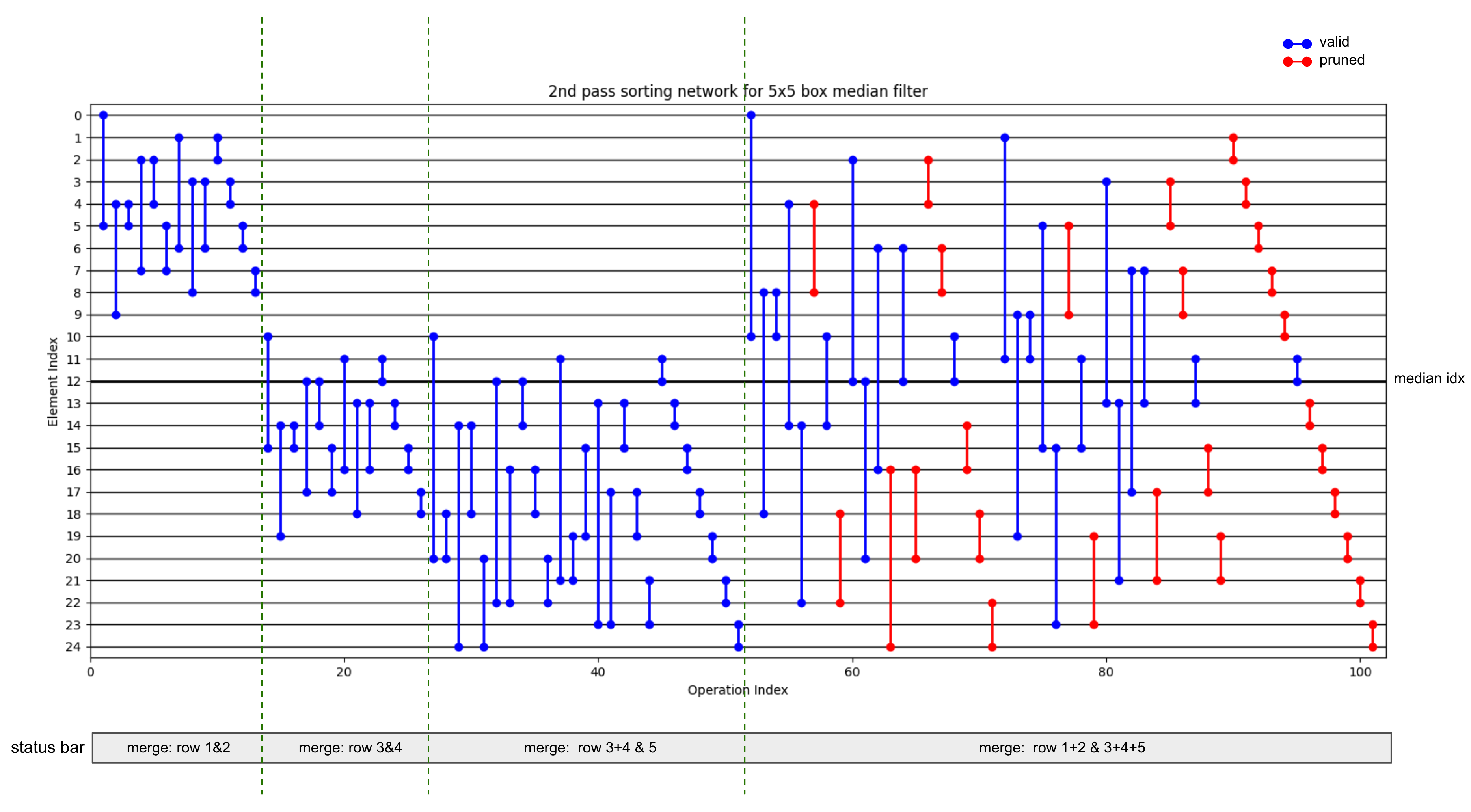
Figure 2: 5x5 median filter 2nd pass sorting network, with illustration for the pruned operations.#
Single Channel Inputs#
The 3x3 kernel functions processes single channel input images with different agen settings from other kernel sizes.
1st pass#
In the 1st pass, for the 3x3 kernel, single channel images are loaded with deinterleaving as double vectors with agen stride 2, separating odd and even elements into low and high parts of the double vectors. Each iteration processes 2 groups of output pixels, which are indeed the odd- and even-indexed output pixels. (Note that the input and output indices below are just used to illustrate the number of pixels involved, not the actual pixel coordinates.)
Input pixel index |
0 |
1 |
2 |
3 |
|---|---|---|---|---|
Out pixel 0 |
\(\text{dv}_0.\text{lo}\) |
\(\text{dv}_0.\text{hi}\) |
\(\text{dv}_1.\text{lo}\) |
\ |
Out pixel 1 |
\ |
\(\text{dv}_0.\text{hi}\) |
\(\text{dv}_1.\text{lo}\) |
\(\text{dv}_1.\text{hi}\) |
Then temporary results for odd and even indices are merged by interleaving store to the temporary result buffer.
While for 5x5 and 5x7 kernels, single channel images are loaded as single vectors with agen stride 1, processing 1 group of output pixels per iteration:
Pixel index |
0 |
1 |
… |
KW - 1 |
|---|---|---|---|---|
Out pixel 0 |
\(\text{v}_0\) |
\(\text{v}_1\) |
… |
\(\text{v}_{\text{KW}-1}\) |
2nd pass#
In the 2nd pass, the 3x3 kernel processes output pixels by double vector, while 5x5 and 5x7 kernels process the output pixels by single vector. This is due to the fact that in the 2nd pass, all elements in the kernel window are loaded into vector registers in order to find the median. If double vector is used, the 5x5 and 5x7 kernels will be short of vector registers. Consequently, single vector is utilized in the 2nd pass for larger kernels.
2S16 Input#
For channel-interleaved input 2S16, the 1st pass kernel functions of all kernel sizes load the input with deinterleaving into double vectors of agen stride 2, seperating the 2 channels into low and high parts of the double vectors. Each iteration processes 1 group of output pixels, where the 2 channels are calculated separately by:
Input pixel index |
0 |
1 |
… |
KW - 1 |
|---|---|---|---|---|
Output pixel 0, 1st channel |
\(\text{dv}_0.\text{lo}\) |
\(\text{dv}_1.\text{lo}\) |
… |
\(\text{dv}_{\text{KW}-1}.\text{lo}\) |
Output pixel 0, 2nd channel |
\(\text{dv}_0.\text{hi}\) |
\(\text{dv}_1.\text{hi}\) |
… |
\(\text{dv}_{\text{KW}-1}.\text{hi}\) |
The 2 channels of temporary results are merged by interleaving store to the temporary result buffer.
The 2nd pass kernel functions do not differentiate 2S16 inputs from single channel inputs, treating the 2 channels in the temporary results of the 1st pass as individual pixels, and directly generating channel-interleaved final outputs.
Performance#
Execution Time is the average time required to execute the operator on a single VPU core.
Note that each PVA contains two VPU cores, which can operate in parallel to process two streams simultaneously, or reduce execution time by approximately half by splitting the workload between the two cores.
Total Power represents the average total power consumed by the module when the operator is executed concurrently on both VPU cores.
For detailed information on interpreting the performance table below and understanding the benchmarking setup, see Performance Benchmark.
ImageSize |
KernelSize |
ImageFormat |
Execution Time |
Submit Latency |
Total Power |
|---|---|---|---|---|---|
1920x1080 |
3x3 |
U8 |
0.220ms |
0.020ms |
16.616W |
1920x1080 |
3x3 |
S8 |
0.220ms |
0.020ms |
16.997W |
1920x1080 |
3x3 |
U16 |
0.405ms |
0.019ms |
16.415W |
1920x1080 |
3x3 |
S16 |
0.405ms |
0.019ms |
16.796W |
1920x1080 |
3x3 |
2S16 |
0.796ms |
0.020ms |
16.897W |
1920x1080 |
3x3 |
U32 |
0.804ms |
0.021ms |
16.314W |
1920x1080 |
3x3 |
S32 |
0.804ms |
0.021ms |
16.698W |
1920x1080 |
5x5 |
U8 |
2.172ms |
0.020ms |
11.619W |
1920x1080 |
5x5 |
S8 |
2.173ms |
0.020ms |
12.003W |
1920x1080 |
5x5 |
U16 |
4.106ms |
0.020ms |
11.619W |
1920x1080 |
5x5 |
S16 |
4.107ms |
0.019ms |
12.003W |
1920x1080 |
5x5 |
2S16 |
8.098ms |
0.021ms |
12.003W |
1920x1080 |
5x5 |
U32 |
8.258ms |
0.021ms |
11.518W |
1920x1080 |
5x5 |
S32 |
8.258ms |
0.021ms |
11.619W |
1920x1080 |
5x7 |
U8 |
3.440ms |
0.020ms |
11.136W |
1920x1080 |
5x7 |
S8 |
3.440ms |
0.020ms |
11.518W |
1920x1080 |
5x7 |
U16 |
6.509ms |
0.020ms |
11.034W |
1920x1080 |
5x7 |
S16 |
6.509ms |
0.020ms |
11.418W |
1920x1080 |
5x7 |
2S16 |
13.004ms |
0.021ms |
12.285W |
1920x1080 |
5x7 |
U32 |
13.099ms |
0.021ms |
11.418W |
1920x1080 |
5x7 |
S32 |
13.099ms |
0.022ms |
11.802W |
Reference#
NVIDIA VPI Documentation: https://docs.nvidia.com/vpi/algo_median_filter.html