VSS Warehouse Blueprint - 3D Vision AI Profile#
Overview#
Introduction#
The VSS Warehouse Blueprint’s 3D Vision AI Profile is a comprehensive guide to building a 3D intelligent video analytics system. It provides a detailed overview of the system architecture, data flow, and key components.
Deployment Architecture#
Components and Interactions#
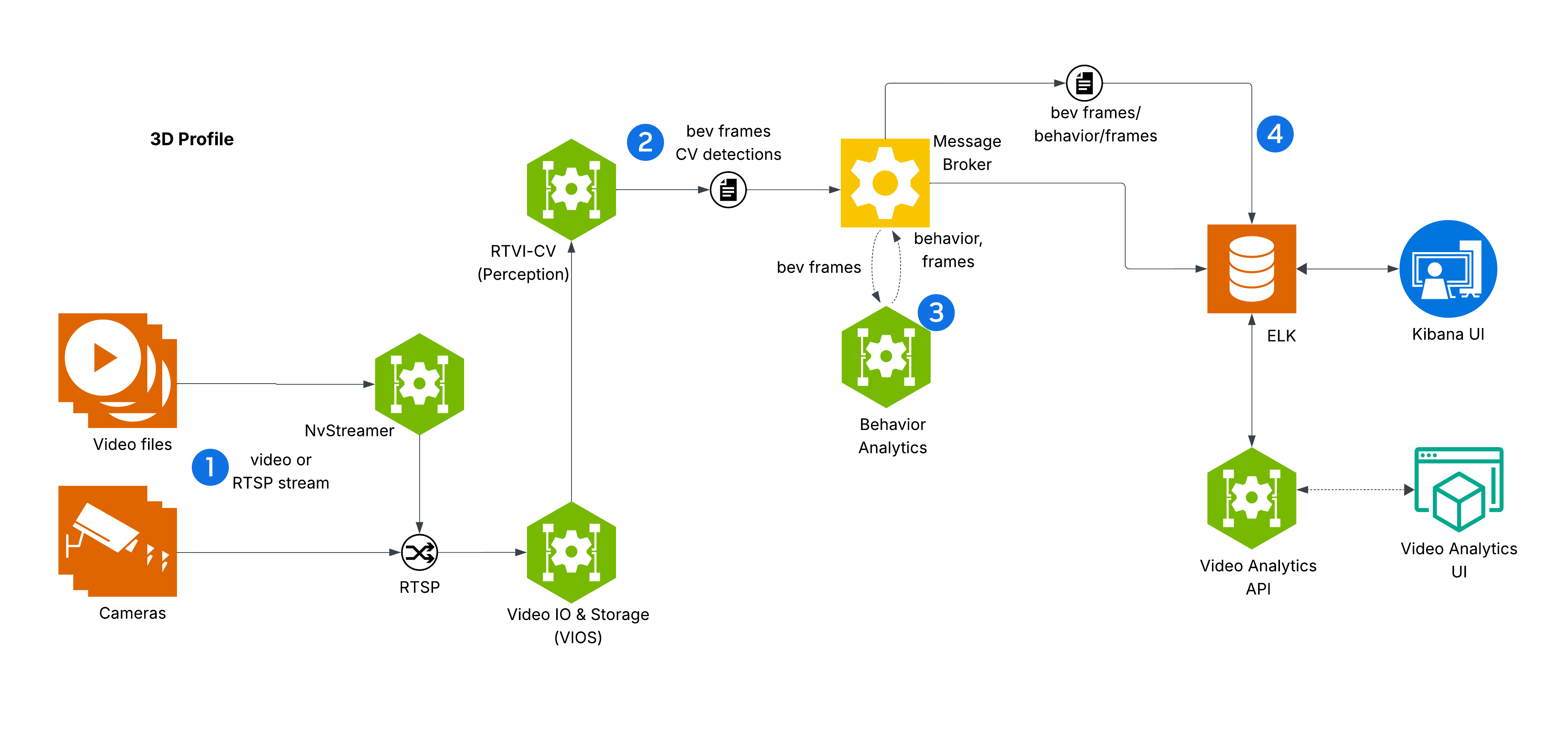
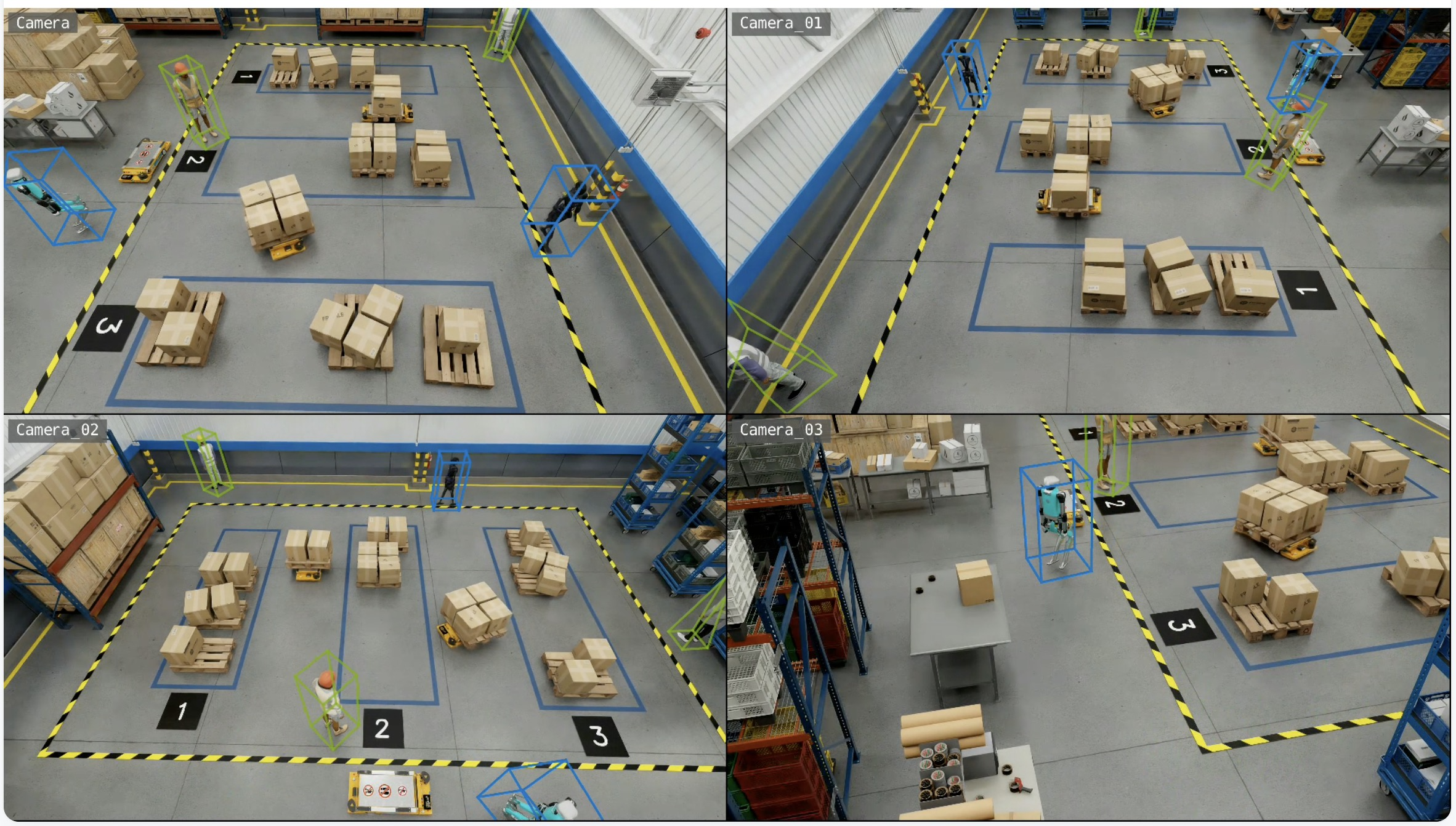
The diagram depicts VSS Warehouse 3D Blueprint, emphasizing 3D multi-camera detection, tracking, and behavior analytics for safety events and metrics. Below is a breakdown of the components and their interactions.
Input Source
Videos: Raw video data stored in a filesystem, serving as input for processing.
NvStreamer (link): A microservice that streams videos via RTSP (Real-Time Streaming Protocol) to the VIOS (Video IO & Storage). NvStreamer can be swapped with real-world cameras.
Video IO & Storage (VIOS) (link)
VIOS ingests video streams from NvStreamer via RTSP.
It records the streams and forwards them (via RTSP) to the DeepStream microservice for further processing.
DeepStream (link)
DeepStream processes RTSP streams for 3D multi-camera detection and tracking, utilizing the Sparse4D model (link) to generate BEV (Bird’s Eye View) outputs.
It sends frame data, including detected and tracked object IDs, in Protobuf format to the message broker via the
mdx-bevtopic.
Message Broker (Kafka or Redis)
The message broker serves as the central hub for data distribution, using Protobuf for all data exchanges.
Kafka (Kafka): High-throughput message broker optimized for datacenter deployments with robust persistence and scalability.
Redis Streams: Lightweight message broker ideal for edge deployments with minimal memory footprint and low-latency requirements.
It also functions as a control bus, managing notifications (in JSON, via
mdx-notification) for calibration updates, such as new ROI or tripwire definitions.
Behavior Analytics (link)
This microservice consumes
mdx-bevdata (Protobuf) from the message broker.It processes the data to generate behavior analytics, safety insights, and metrics.
The resulting data, in Protobuf format, is sent back to the message broker for indexing into Elasticsearch.
Storage
ELK (Elasticsearch, Logstash, Kibana) (ELK): Logstash retrieves BEV outputs and safety violation frames from the message broker, converts Protobuf to JSON, stores the data in Elasticsearch, and supports querying and visualization.
Visualization
External Interfaces
API Gateway and MCP (API Gateway/MCP): Enables external systems to interact with the events data through API calls.
Key Technologies#
Microservices: Components like NvStreamer, VIOS, DeepStream, and Behavior Analytics are modular microservices.
RTSP: Facilitates real-time video streaming.
Protobuf: Ensures efficient, compact data exchange.
Message Broker: Manages data distribution and control messaging.
ELK Stack: Supports storage, logging, and visualization.
JSON: Used for notifications and calibration data.
Setup and Configuration#
Testing and Validation#
Kibana UI#
Note
In the new Kibana UI (versions 8.0 and later), “Index Patterns” have been renamed to “Data Views”.
Check for BEV, Frames and Behavior Data Views in Kibana:
Launch Chrome browser
In the address bar enter
http://<IP_address>:5601
In the user interface, navigate to the Management -> Stack Management section and select Data Views under Kibana. If the data views are not visible, create new data view (via “Create data view” button on the top right corner) for mdx-bev, mdx-frames and mdx-behavior.
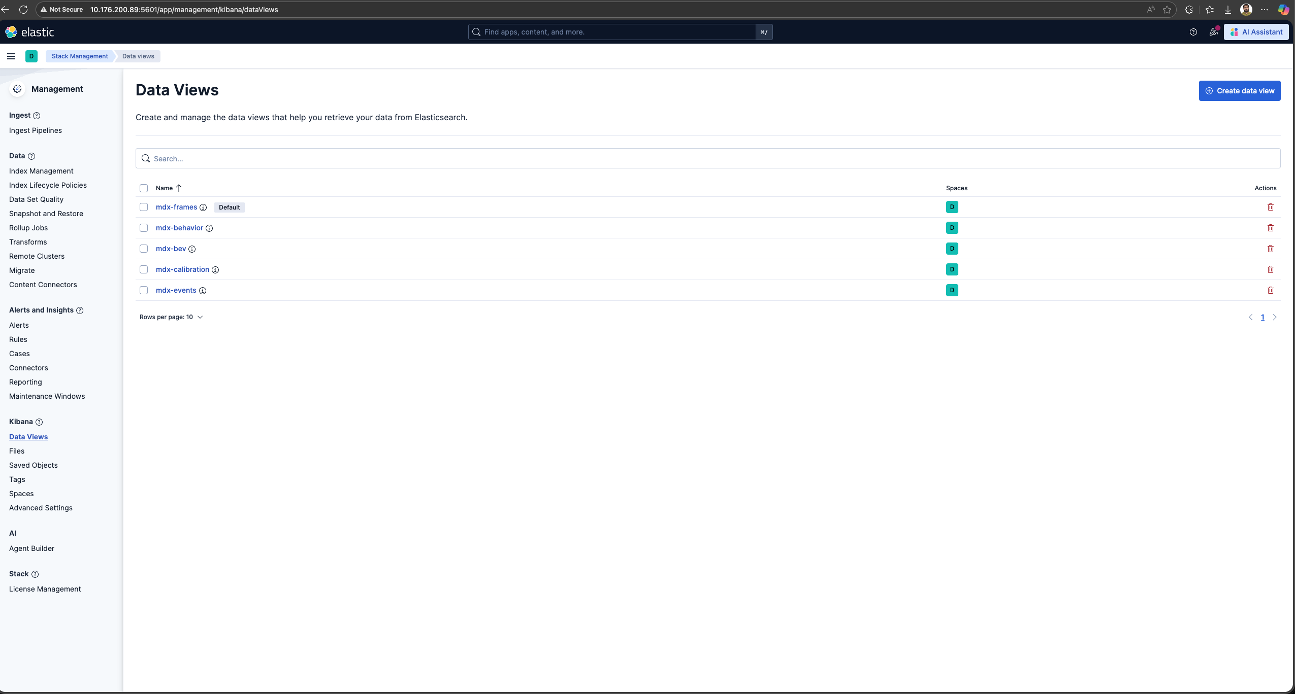
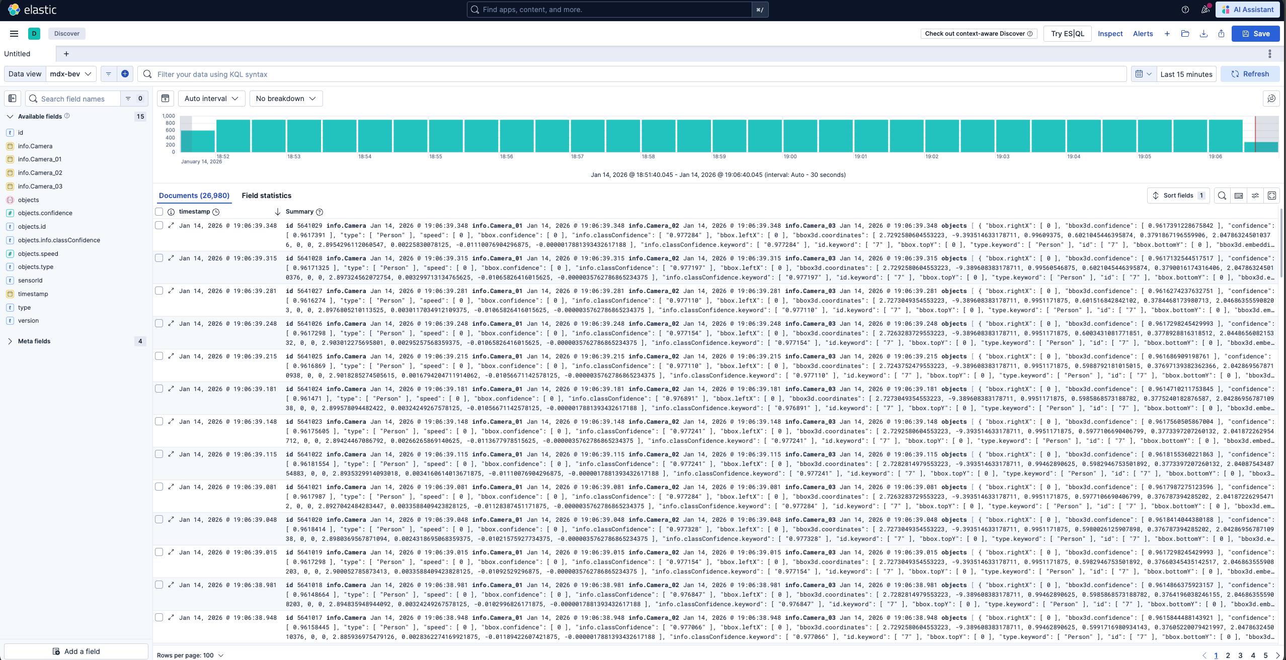
Browse the Kibana UI, discover the data views and visualize the data.
VIOS UI#
Note
At this point the web-based application is only available for Chrome browser running on Linux, Windows or MacOS, details can be found in VST docs.
Launch Chrome browser.
In the address bar enter
http://<IP_address>:30888/vst/.
Configure
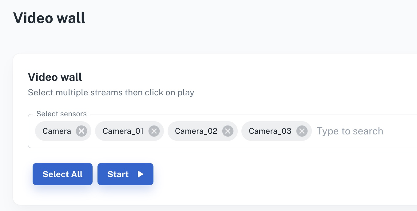
View VIOS Video Wall
Enable Overlay settings (instructions here), to view 3D object detection and tracking results.
KPI & Metrics#
Performance#
System |
Model |
No. of streams |
Fps |
(NvStreamer + VIOS + DeepStream) latency |
Behavior-analytics latency |
E2E latency |
|---|---|---|---|---|---|---|
RTX6000pro + AMD EPYC 9124 16-Core Processor (3.0GHz) |
Sparse4D |
4 |
30 |
78 ms |
21 ms |
99 ms |
NVIDIA DGX Spark + ARM Cortex-X925/A725 20-Core (4.0GHz) |
Sparse4D |
4 |
15 |
117 ms |
21 ms |
138 ms |
NVIDIA IGX Thor + ARM 14-Core (2.6GHz) |
Sparse4D |
4 |
15 |
153 ms |
27 ms |
180 ms |
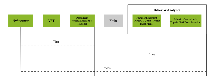
Latency Measurements on RTX6000pro (p50)
The above diagram shows the p50 latency of the VSS Warehouse 3D Blueprint, measured using an RTX6000pro GPU and an AMD EPYC 9124 16-Core Processor (3.0GHz) with 4 streams at 30 fps for Sparse4D model.

Latency Measurements on DGX Spark (p50)
The above diagram shows the p50 latency of the VSS Warehouse 3D Blueprint, measured using an NVIDIA DGX Spark + ARM Cortex-X925/A725 20-Core (4.0GHz) with 4 streams at 30 fps for Sparse4D model.

Latency Measurements on IGX Thor (p50)
The above diagram shows the p50 latency of the VSS Warehouse 3D Blueprint, measured using an NVIDIA IGX Thor + ARM 14-Core (2.6GHz) with 4 streams at 15 fps for Sparse4D model.
The system demonstrates the following p50 latency breakdown:
Video pipeline (nvStreamer + VIOS + DeepStream): 78ms with RTX6000pro, 117ms with DGX Spark, and 153ms with IGX Thor
Behavior analytics pipeline: 21ms with RTX6000pro, 21ms with DGX Spark, and 27ms with IGX Thor
The end-to-end system latency is 99ms with RTX6000pro, 138ms with DGX Spark, and 180ms with IGX Thor at p50.
Note
The latency may vary based on the hardware, the number of objects in a scene, the number of ROIs and tripwires, and the machine’s load.
Customization#
The Blueprint supports several levels of customization:
Data Level: Add, remove, or replace cameras while maintaining the existing workflow.
Model Level: Fine-tune perception models to better suit your use cases.
Application Level: Build new microservices or applications using the provided APIs and components.
Microservice Level: Modify existing microservices from source code to extend functionality.
Adding New Cameras#
Prepare and Calibrate New Cameras#
Before integrating a camera into the Warehouse Blueprint 3D app, you must generate a proper calibration file.
Synthetic Cameras
Create synthetic cameras and generate data using Omniverse. For details, see: Simulation and Synthetic Data Generation Page.
Generate calibration files using the omni.replicator.agent.camera_calibration extension. For more information, refer to: Simulation-Based Calibration
Real Cameras
The 3D Blueprint supports both live RTSP feeds and recorded video files from real cameras. Both require proper calibration files.
For detailed instructions on calibrating real cameras, see Manual Calibration Guide.
Integrating New Cameras#
There are two approaches to integrate new cameras into the 3D Warehouse Blueprint:
Option 1: NvStreamer/VIOS (Recorded Videos)
Use this approach for recorded videos or when managing cameras using NvStreamer/VIOS.
Configure NvStreamer/VIOS:
For recorded videos:
First upload videos to NvStreamer (see uploading videos section)
Then add RTSP links to VIOS (see add camera section)
For live feeds: Directly add RTSP links to VIOS (see add camera section)
Update DeepStream Configuration:
Modify the source-list in the DeepStream configuration.
Update sensor count and batch size settings.
See source config section for more details.
Update Calibration File:
Maintain a single calibration.json file per deployment.
Add new camera information following the schema defined in Schema Documentation.
Refer to Prepare and Calibrate New Cameras for guidance.
Option 2: Live RTSP Feeds
Use this approach for realtime RTSP streams when you want to define camera configurations declaratively via a JSON file.
Create a Sensor Info File (
camera_info.json):{ "sensors": [ { "camera_name": "camera-01", "rtsp_url": "rtsp://192.168.1.100:554/stream1", "group_id": "entrance-group", "region": "building-A" }, { "camera_name": "camera-02", "rtsp_url": "rtsp://192.168.1.101:554/stream1", "group_id": "entrance-group", "region": "building-A" } ] }
Required fields:
camera_name,rtsp_urlOptional fields:
group_id,region(can also be obtained from calibration data)Configure Blueprint Configurator Environment Variables:
SENSOR_INFO_SOURCE=file
SENSOR_FILE_PATH=<path_to_camera_info.json>
Update Calibration File:
Ensure your
calibration.jsonincludes calibration data for all cameras defined in the sensor info file.Refer to Prepare and Calibrate New Cameras for guidance.
Configuring Number of Streams
For both approaches, the number of streams/sensors to be processed can be configured in two ways:
Static Configuration: Set the
NUM_STREAMSenvironment variable to specify the desired number of streams.NUM_STREAMS=4
The configured number of streams should be less than or equal to the maximum streams supported by your hardware profile and deployment mode. Blueprint Configurator can be used to automatically cap the stream count using the formula:
final_stream_count = min(NUM_STREAMS, max_streams_supported). For more details, refer to the How to Count Files Dynamically (Prerequisites) section in Blueprint Configurator Documentation.Dynamic Configuration: Use the Blueprint Configurator’s prerequisite operations to automatically count the number of video files in the recorded videos directory and use that count for configuration updates. Please note that this approach cannot be used for live RTSP feeds.
Example: Automatically determine stream count from video files in dataset directory:
# In blueprint_config.yml
commons:
  # Step 1: Count video files BEFORE variable processing
  prerequisites:
    3d:
      - operation_type: "file_management"
        target_directories:
          - "${MDX_DATA_DIR}/videos/warehouse-3d-app"
        file_management:
          action: "file_count"
          parameters:
            pattern: "*.mp4"
          output_variable: "available_video_count"  # Stores count (e.g., 6)

  # Step 2: Use the count to compute final stream count
  variables:
    3d:
      # Cap to minimum of: available videos, GPU limit
      - final_stream_count: "min(${available_video_count}, ${max_streams_supported})"

  # Step 3: Use computed variable in config file updates
  file_operations:
    3d:
      - operation_type: "yaml_update"
        target_file: "${DS_CONFIG_DIR}/config.yaml"
        updates:
          num_sensors: ${final_stream_count}
How it works: If your dataset directory has 6 video files, and GPU supports max 4 streams, the configurator computes:
final_stream_count = min(6, 4) = 4. For more details, refer to the How to Count Files Dynamically (Prerequisites) section in Blueprint Configurator Documentation.
Camera Grouping Utilities#
The 3D Blueprint uses multi-camera BEV (Bird’s Eye View) perception systems that require cameras to be organized into groups. Each camera group defines a set of cameras with overlapping fields of view that work together for 3D detection and tracking.
The spatialai_data_utils library provides the following functionality:
Calculate BEV origin and dimensions for each camera group.
Partition cameras into clusters using spatial clustering algorithms for distributed 3D model deployment.
Filter and select specific cameras for processing.
Generate FOV polygons from camera intrinsic/extrinsic matrices.
Visualize camera coverage and group assignments.
To install the library:
pip install spatialai_data_utils==1.1.0 --extra-index-url=https://edge.urm.nvidia.com/artifactory/api/pypi/sw-metropolis-pypi/simple
BEV Group Origin Calculation#
Use calculate_origin.py to calculate BEV origin and dimensions for camera groups, filter cameras, and generate FOV visualizations.
The algorithm works as follows:
FOV Calculation: By default, the tool uses frustum-based FOV generation. It projects camera view frustums onto the ground plane using camera intrinsic (focal length, principal point) and extrinsic (rotation, translation) matrices. The frustum is intersected with a configurable height range to create a polygon representing the camera’s ground coverage.
Group Bounds: For each camera group, the tool computes the union of all camera FOV polygons and calculates the bounding box with optional dilation.
Origin Calculation: The BEV origin is computed as the centroid of the union FOV polygon, and dimensions are derived from the bounding box of the union, providing the coordinate reference for multi-camera tracking.
Origin calculation is required when setting up a new multi-camera deployment or when camera configurations change. This functionality is already integrated into the Blueprint configurator, so manual execution is typically not necessary. However, if you need to run it as a standalone script for debugging, custom workflows, or batch processing, the example commands below demonstrate the available options.
cd $MDX_SAMPLE_APPS_DIR/deploy-warehouse-compose/modules/bev_group_utils/
# Using dataset folder (auto-detects calibration.json)
python calculate_origin.py data/scene

# Using direct path to calibration file
python calculate_origin.py data/scene/calibration.json

# Custom height range for ground plane intersection
python calculate_origin.py data/scene/calibration.json --height-range 0.5 2.5

# Process only specific sensors
python calculate_origin.py data/scene/calibration.json --sensor-names Camera1,Camera2,Camera3

# Specify output file
python calculate_origin.py data/scene/calibration.json -o calibration_with_origins.json

# Overwrite the original calibration file
python calculate_origin.py data/scene/calibration.json --overwrite

# Include visualization (uses black background if map file not provided)
python calculate_origin.py data/scene/calibration.json --visualize

# Include visualization with map file
python calculate_origin.py data/scene/calibration.json --map_file data/scene/Top.png --visualize

# Use existing FOV polygons from calibration instead of frustum calculation
python calculate_origin.py data/scene/calibration.json --prefer-existing-fov

# Constrain FOV with scene bounds
python calculate_origin.py data/scene/calibration.json \
    --scene-bounds -30 -40 30 40 --max-camera-distance 25.0
Use --help to list all available arguments.
Key options:
--output,-o: Output calibration file path (default: input_with_origins.json).--overwrite: Overwrite the input calibration file (mutually exclusive with--output).--map_file: Path to map image for visualization (uses black background if not provided).--sensor-names: Filter to process only specified sensor names (comma-separated).--n-sensor-groups: Number of sensor groups to create when group field is missing (default: 1).--dilation: Dilation distance in meters for group bounds calculation (default: 1.0).--height-range: Height range (min, max) in meters for ground plane intersection (default: 1.0 3.0).--max-camera-distance: Maximum distance in meters to constrain frustum polygons (default: 30.0).--scene-bounds: Scene bounds (min_x, min_y, max_x, max_y) in meters to clip frustum polygons.--prefer-existing-fov: Use existing FOV from calibration file, fall back to frustum if not available.--visualize: Generate visualization of groups.--vis_separate_images: Generate separate visualization images per group instead of combined.
Camera Clustering#
For 3D model inference and deployment, cameras need to be partitioned into non-overlapping groups where each group is handled by a separate 3D model instance. Use create_camera_clusters.py to partition cameras into spatially compact clusters based on FOV coverage and spatial proximity. This tool assigns ALL cameras to exactly N clusters, ensuring efficient distribution of camera workloads across multiple model instances.
Note
The clustering algorithm may not always produce optimal results depending on camera layout and configuration. Always use visualization (enabled by default) to verify the clustering results and manually adjust using reassign_camera_groups.py if needed.
Note
By default, the tool auto-tunes clustering parameters (start camera index, overlap threshold, distance threshold) using a grid search to find optimal settings. Use --disable_param_tuning to skip auto-tuning and use the provided parameters directly.
Running Camera Clustering#
cd $MDX_SAMPLE_APPS_DIR/deploy-warehouse-compose/modules/bev_group_utils/
# Basic usage with densify mode (default, visualization on by default)
python create_camera_clusters.py data/scene --max_camera_per_group 10

# Use balanced mode for evenly distributed clusters
python create_camera_clusters.py data/scene --max_camera_per_group 10 --mode balanced

# Densify mode with custom thresholds (disabling auto-tuning)
python create_camera_clusters.py data/scene --max_camera_per_group 10 --mode densify \
    --min_overlap_threshold 0.3 --max_distance_threshold 10.0 --disable_param_tuning

# Balanced mode with specific number of clusters
python create_camera_clusters.py data/scene --max_camera_per_group 8 --mode balanced \
    --n_clusters 5

# Specify output path and overwrite input file
python create_camera_clusters.py data/scene --max_camera_per_group 10 \
    --output data/scene/calibration_clustered.json --overwrite

# Use existing FOV polygons from calibration instead of frustum calculation
python create_camera_clusters.py data/scene --max_camera_per_group 10 --prefer_existing_fov

# Custom auto-tuning search grids
python create_camera_clusters.py data/scene --max_camera_per_group 10 \
    --tuning_overlap_grid 0.1 0.2 0.3 --tuning_distance_grid 5.0 8.0 10.0
Use --help to list all available arguments.
Key options:
--max_camera_per_group: Maximum cameras per cluster (required). Has higher priority than--n_clusters.--n_clusters: Override auto-calculated number of clusters.--mode: Clustering mode - “balanced” or “densify” (default: densify).--output: Output path for the clustered calibration file.--overwrite: Overwrite the input calibration file.--output_suffix: Suffix for output files (default: “clustered”).--start_camera_index: Starting camera index for seeding (default: 0).--min_overlap_threshold: Minimum required FOV overlap (default: 0.2).--max_distance_threshold: Maximum allowed centroid distance in meters (default: 8.0).--max_cascade_depth: Maximum recursion depth for densify-mode cascade reassignment (default: 3).--prefer_existing_fov: Use existing FOV polygons in calibration instead of calculating from frustum.--height_range: Height range (min, max) in meters for ground plane intersection (default: 1.0 8.0).--image_size: Image dimensions (width, height) in pixels for frustum calculation (default: 1920 1080).--max_camera_distance: Maximum distance in meters for frustum calculation (default: 30.0).--dilation: Buffer distance in meters for cluster bounding boxes (default: 8.0).--disable_param_tuning: Disable auto-tuning of clustering parameters.--tuning_overlap_grid: Custom overlap thresholds (0-1) to search when auto-tuning.--tuning_distance_grid: Custom centroid distance thresholds (meters) to search when auto-tuning.--tuning_start_index_grid: Seed camera indices to try when auto-tuning.--tuning_workers: Number of parallel workers for auto-tuning (0=auto, 1=disable parallelism).--vis_no_camera_id_labels: Disable drawing camera IDs on the visualization.--vis_separate_images: Generate separate visualization images per cluster instead of combined.
Clustering Modes
densify(default): Prioritizes creating full, densely-packed clusters. Uses cascade reassignment to handle unassigned cameras by recursively attempting to place them in nearby clusters.balanced: Enforces strict thresholds for overlap and distance. Splits oversized clusters to maintain balance across all groups.
Cluster Count Calculation
The number of clusters is determined by the following logic:
If
--n_clustersis not provided, it is auto-calculated asceil(total_cameras / max_camera_per_group).If
--n_clustersis explicitly set but would violate the--max_camera_per_groupconstraint (i.e., requires more clusters than specified), the tool overrides--n_clusterswith the minimum required value and logs a warning.If
--n_clusters=1is set buttotal_cameras > max_camera_per_group, an error is raised.
This ensures --max_camera_per_group always takes priority to guarantee each cluster stays within the specified camera limit.
Finding Optimal Clustering Parameters#
Use find_suggested_cluster_params.py to search for optimal clustering parameters. This tool performs a grid search over overlap thresholds, distance thresholds, and seed camera indices to find settings that produce compact, capacity-respecting clusters:
# Basic usage - find best parameters for clustering
python find_suggested_cluster_params.py data/scene --max_camera_per_group 10

# Custom search grids
python find_suggested_cluster_params.py data/scene --max_camera_per_group 10 \
    --overlap_grid 0.1 0.2 0.3 --distance_grid 5.0 8.0 10.0

# Specify seed camera indices to try
python find_suggested_cluster_params.py data/scene --max_camera_per_group 10 \
    --start_index_grid 0 5 10

# Use random sampling for start indices
python find_suggested_cluster_params.py data/scene --max_camera_per_group 10 \
    --start_index_seed 42

# Show more candidates with verbose output
python find_suggested_cluster_params.py data/scene --max_camera_per_group 10 \
    --top_k 10 --verbose
Key options:
--max_camera_per_group: Maximum cameras per cluster (required).--mode: Clustering mode to evaluate - “balanced” or “densify” (default: densify).--prefer_existing_fov: Use existing FOV polygons instead of calculating from frustum.--max_camera_distance: Maximum distance in meters for frustum calculation (default: 30.0).--height_range: Height range (min, max) in meters for ground plane intersection (default: 1.0 8.0).--image_size: Image dimensions (width, height) in pixels for frustum calculation (default: 1920 1080).--max_cascade_depth: Maximum recursion depth for densify-mode cascade (default: 3).--overlap_grid: List of overlap thresholds (0-1) to search.--distance_grid: List of centroid distance thresholds (meters) to search.--start_index_grid: Seed camera indices to try.--start_index_seed: Random seed for auto-generated start camera indices.--top_k: Number of top candidates to display (default: 5).--workers: Number of parallel workers for the sweep (0=auto, 1=disable parallelism).--verbose: Enable verbose logging.
The output ranks candidates by score (lower is better), showing unassigned camera count, overflow, and scatter metrics for each parameter combination.
Camera Group Reassigning#
Use reassign_camera_groups.py to manually reassign cameras to different existing BEV groups. Common use cases include:
Fixing suboptimal clustering: Move cameras that were incorrectly assigned by the automatic clustering algorithm.
Balancing cluster sizes: Redistribute cameras between groups to achieve more even workload distribution.
Iterative refinement: Fine-tune cluster assignments after reviewing visualization results.
cd $MDX_SAMPLE_APPS_DIR/deploy-warehouse-compose/modules/bev_group_utils/
# Move cameras to different groups
python reassign_camera_groups.py data/calibration.json \
    --move cam-01:bev-sensor-2 cam-05:bev-sensor-3

# Specify output path
python reassign_camera_groups.py data/calibration.json \
    --move cam-01:bev-sensor-2 --output data/calibration_updated.json

# Overwrite the original file
python reassign_camera_groups.py data/calibration.json \
    --move cam-01:bev-sensor-2 --overwrite

# Strict mode - fail if camera or group is missing
python reassign_camera_groups.py data/calibration.json \
    --move cam-01:bev-sensor-2 --strict

# Use existing FOV polygons instead of frustum calculation
python reassign_camera_groups.py data/calibration.json \
    --move cam-01:bev-sensor-2 --prefer_existing_fov
Key options:
--move: Mappings ofcamera_id:group_name(space separated) to reassign (required).--output: Output path for updated calibration (default:<input>_reassigned.json).--overwrite: Overwrite the input calibration file in-place.--output_suffix: Suffix for output files (default: “reassigned”).--strict: Fail if a camera or target group is missing; otherwise skip with warning.--prefer_existing_fov: Use existing FOV from calibration, fall back to frustum if not available.--map_file: Path to map image for visualization (auto-detectsTop.pngif omitted).--dilation: Dilation distance in meters when recomputing group bounds (default: 1.0).--height_range: Height range (min, max) in meters for ground plane intersection (default: 1.0 3.0).--image_size: Image dimensions (width, height) in pixels for frustum calculation (default: 1920 1080).--max_camera_distance: Maximum distance in meters for frustum calculation (default: 30.0).--vis_no_camera_id_labels: Disable drawing camera IDs on the visualization.
Model Customization#
Perception Model Fine-tuning#
The Blueprint uses Sparse4D as its primary perception model. To customize:
Fine-tune Sparse4D using TAO (Sparse4D Fine-tuning Guide)
Configure DeepStream to use your custom model (model configuration guide)
Application Customization#
The Blueprint uses a modular microservices architecture with the following communication channels:
Message Broker (Kafka or Redis)
Elasticsearch database
REST APIs
User can build their own microservices by consuming data from above channels.
For complete API documentation, see API Reference Page.
Available Service Ports#
The following ports are used during the deployment, and users can leverage for any potential integration:
Service Component |
Port Number |
|---|---|
Calibration Toolkit |
8003 |
Kafka |
9092 |
ZooKeeper |
2181 |
Elasticsearch |
9200 |
Kibana |
5601 |
NvStreamer |
31000 |
VIOS |
30888/vst |
VSS Video Analytics API |
8081 |
Analytics Microservices Customization (Advanced)#
For detailed information about customizing specific analytics microservices, refer to:
Hardware Config Customization#
The 3D Warehouse Blueprint requires several configuration files to be properly tuned based on your GPU hardware and deployment requirements. When changing hardware (e.g., switching from H100 to L4 GPU) or adjusting the number of video streams, multiple configuration files must be updated to ensure optimal performance and prevent GPU overload.
Configuration Files Requiring Hardware-Based Updates#
The following table lists the configuration files that typically require updates when hardware changes:
Configuration File |
Parameters to Update |
Why Update is Needed |
|---|---|---|
|
|
Batch sizes must match stream count; timeout values vary by GPU processing speed |
|
|
Same as above for Redis-based deployments |
|
|
Sensor count must match the number of active streams |
|
|
Input shape dimensions depend on stream count (e.g., |
|
|
Must align with GPU capacity and stream count |
|
|
Device limits and overlay settings vary by GPU capability |
|
|
Same as above for Redis-based deployments |
Certain GPUs require additional optimizations. For example, IGX-THOR gets:
Extended
batched-push-timeout(80000ms) for DeepStream configsenable_overlay_skip_frameenabled in VST configs for better performance
There are two approaches to customize these configuration files:
Approach 1: Manual Configuration#
Manually update all required configuration files before deploying the blueprint. This is time consuming, error prone and often not suitable for production deployments.
# Update DeepStream main config
vi <PATH_TO_DS_CONFIG_DIR>/ds-main-config.txt
# Set: max-batch-size=<stream_count>, sgie-batch-size=<stream_count>, batch-size=<stream_count>

# Update DeepStream YAML config
vi <PATH_TO_DS_CONFIG_DIR>/config.yaml
# Set: num_sensors: <stream_count>

# Update DeepStream preprocess config
vi <PATH_TO_DS_CONFIG_DIR>/ds-mtmc-preprocess-config.txt
# Set: network-input-shape=<stream_count>;3;540;960

# Update VST config
vi <PATH_TO_NVSTREAMER_CONFIG_DIR>/vst-config.json
# Set: "nv_streamer_sync_file_count": <stream_count>, "max_devices_supported": <max_streams>
Approach 2: Automatic Config Management using Blueprint Configurator#
The Blueprint Configurator provides a declarative approach to automatically update all required configuration files based on your hardware profile and deployment mode. This is the recommended approach for production deployments and simplifies the configuration management process.
To enable the Blueprint Configurator, in Blueprint Configurator’s environment variables you must set:
ENABLE_PROFILE_CONFIGURATOR=true
By default, the Blueprint Configurator is disabled (ENABLE_PROFILE_CONFIGURATOR=false).
When enabled, it runs before the Blueprint Deployment starts and adjusts configuration files based on the hardware profile and deployment mode as defined in the HARDWARE_PROFILE and MODE environment variables.
The Blueprint Configurator provides a comprehensive set of features for automated profile configuration management:
Feature |
Description |
|---|---|
Configuration File Updates |
Automatically update configuration files in multiple formats:
|
Environment Variable Validation |
Validate environment variables before deployment to catch configuration errors early:
|
Prerequisite Operations |
Run operations before variable processing to dynamically determine values:
|
Variable Computations |
Create computed variables for intermediate calculations and condition checking. Use case: Automatically cap stream count to GPU limits using
|
Execution Order: Prerequisite Operations → Environment Variable Validation → Variable Computations → Configuration File Updates
For detailed information on how to create custom hardware profiles and advanced configuration options, refer to the Profile Configuration Manager section in Blueprint Configurator Documentation.