Camera Calibration#
This section explains how to obtain camera calibration data, top-down view images, and field-of-view (FOV) visualization images, enabling you to perform 3D to 2D projection during training, inference, and visualization.
Tool Activation:
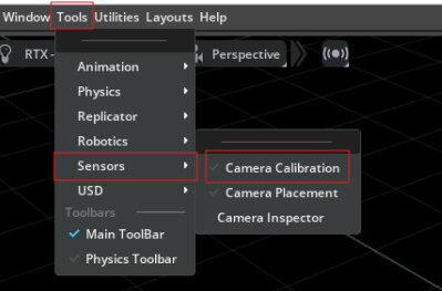
Open Camera Calibration tool by Tools > Sensors > Camera Calibration.
Note
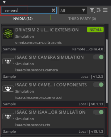
If you cannot find the Camera Calibration tool, please check if the Sensors extension is enabled by Window > Extensions > Search Sensors.
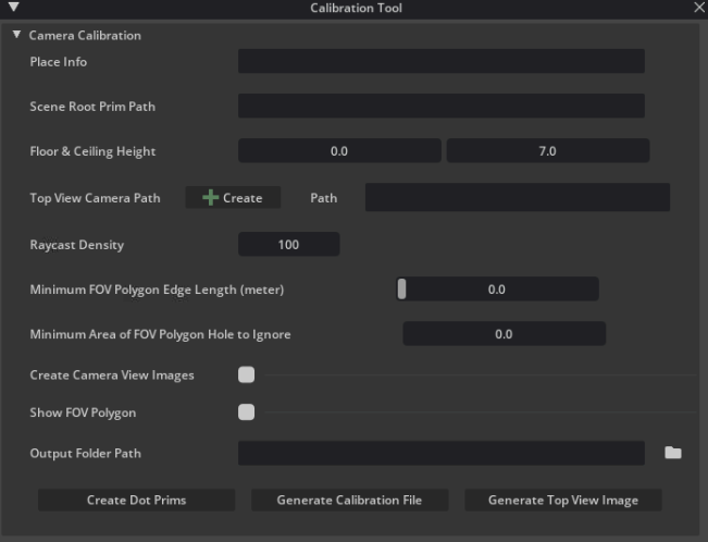
The Camera Calibration panel is shown below.
Quick Start:
Setting:
Scene Loading:
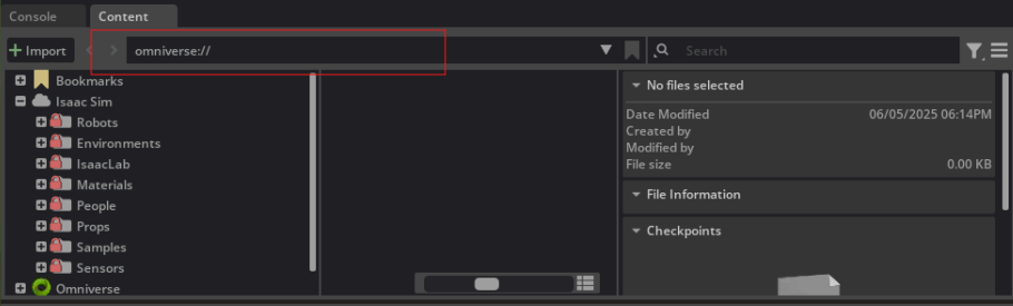
Go to File > Open (Open File window pop up) > Enter your asset path > Click Open File button.
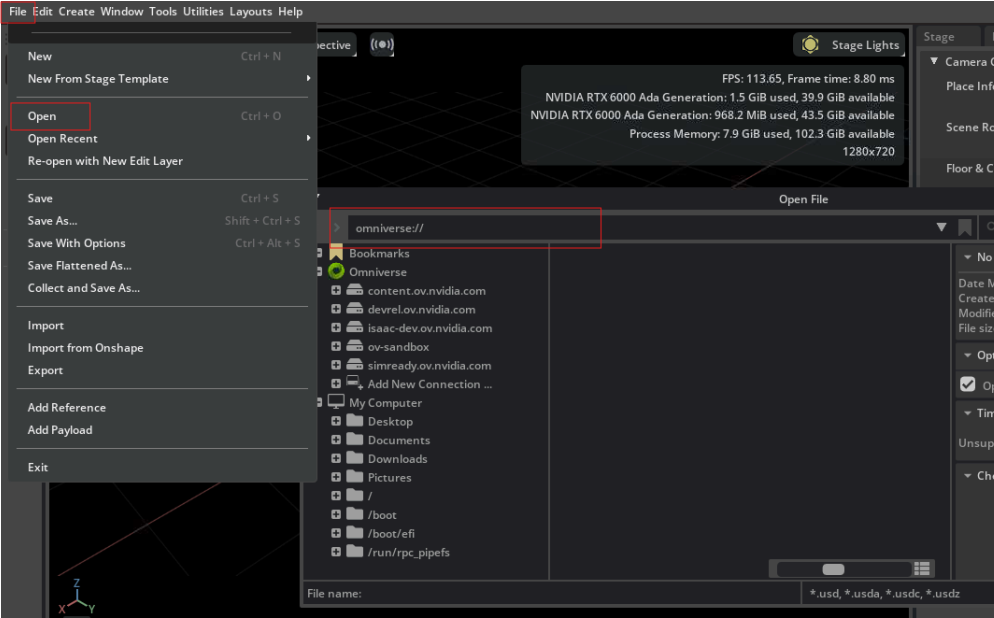
Or go to Content panel at the bottom > Enter your asset path > Press Enter.
Note
Refer to the OMNIVERSE official guidance to learn more about the Content Browser.
NavMesh Enabled: Ensure the NavMesh is set up before starting calibration. In the example asset, NavMesh volumes have already been added.
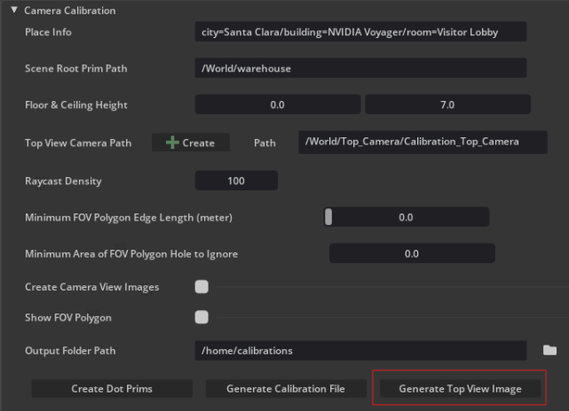
Set the Place Info, Scene Root Prim Path, Floor and Ceiling, Top View Camera Path, and Output Folder Path of the current stage. The Top View Camera Path is generated by clicking the Create button.

Tip
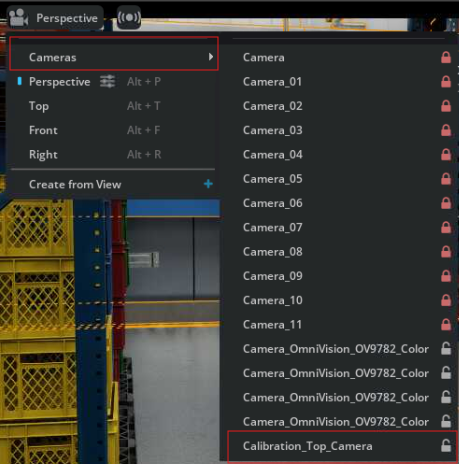
To switch the viewport to the top-view camera, click the Camera icon, then click Cameras > Calibration_Top_Camera.
(optional) Adjustable parameters:
Raycast Density: the density of the raycasts used to visualize the field of view; a higher value means more raycasts and a more accurate field of view visualization.
Minimum FOV Polygon Edge Length: the minimum edge length of the field of view polygon, higher value means more detailed field of view visualization.
Minimum Area of FOV Polygon Hole to Ignore: the minimum area of the holes in the field of view polygon, holes with an area smaller than this value will not be displayed.
Generation:
Generate the calibration file by first clicking the Create Dot Prims button, followed by clicking the Generate Calibration File button.

Generate the top view image by clicking the Generate Top View Image button.
Tip
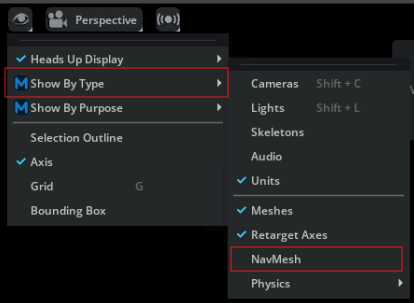
Close NavMesh visualization by the following image when generating the top view image.
Parameter Details:
Place Info: Customize place information for the scene.
Ideally the input field should be an adjustable key + value pair.
Let the key represent the information name, and store the corresponding data in the value field.
Scene Root Prim Path: The root prim path of the target scope to be included in the top-down view.
Top View Camera Path:
A Create button is provided to create a top view camera prim in the scene to cover the target scope.
The top view camera prim will be created at the center of the target scope.
Floor and Ceiling Height: The floor and ceiling height of the scene.
Raycast Density: The density of raycasts used to visualize the field of view; a higher value results in more raycasts and a more accurate field of view visualization.
Minimum FOV Polygon Edge Length: The minimum edge length of the field of view polygon, higher value means more detailed field of view visualization.
Minimum Area of FOV Polygon Hole to Ignore: The minimum area of the holes in the field of view polygon, holes with an area smaller than this value will not be displayed.
Create Camera View Image: Whether the camera view image would be captured and outputted.
Show FOV Polygon: Whether the camera fov would be output. If Show FOV Polygon is enabled, FOV polygon would be rendered in world space with 3d scene UI.
Buttons:
Output Folder Path: The path to the output folder of the generated calibration files (camera view images, calibration info, etc.).
Create Dot Prims: Creates dot prims in the scene for camera calibration. The projection matrix will be estimated via the mapping of 2D coordinates (in the camera view image) to 3D coordinates (in the scene world).
Generate Calibration File: Generates the calibration file for the camera.
Generate Top View Image: Generates the top-view image for the camera. - If Show FOV Polygon is enabled, the FOV polygon of each camera view will be displayed in different copies of the top-view image. - If Create Camera View Images is enabled, the camera view images of each camera will be captured and saved in the output folder.