

EM Solver API
EM Solver API
The EM engine is developed directly by NVIDIA and embedded modularly in the Aerial Omniverse Digital Twin through a specific interface. This makes it possible to integrate different EM engines when needed. This section gives an overview of the key mechanics of that interface.
NVIDIA’s EM engine API provides functions to
- manage the device memory,
- perform EM calculations,
- and copy results to host memory.
All classes, member functions, and variables are defined in the aerial_emsolver_api.h header and use the C++/CUDA primitive data types.
Data types
-
d_complex
Complex-valued data type used in both host code and device code.
-
d_complex4
An array of four
d_complexelements. -
CIRResult
Struct contains:
cir_values: the device buffer storing the CIR values; the size of thecir_valuesper TX isnum_rx * num_samples * num_rx_horz * num_rx_vert * num_rx_pol * num_tx_horz * num_tx_vert * num_tx_pol * num_tapscir_delays: the device buffer storing the CIR delay; the size of thecir_delaysper TX isnum_rx * num_samples * num_rx_horz * num_rx_vert * num_tx_horz * num_tx_vert * num_tapsangles_of_departure: the device buffer storing angle of departure values asfloat2(azimuth, zenith)tuples, in radians, with the same indexing and element count ascir_delays; the angles are defined in the TX panel’s local coordinate systemangles_of_arrival: the device buffer storing angle of arrival values asfloat2(azimuth, zenith)tuples, in radians, with the same indexing and element count ascir_delays; the angles are defined in the RX panel’s local coordinate systemnum_samplesis either 1 or 14, the number of realizations per slot- methods to get index, size, get, and set the CIR values, delays, angles of departure, and angles of arrival for a specific TX/RX antenna pair and tap
-
MultiTimeStepCIRResult
A struct storing batched CIR results for multiple time steps.
All offsets are element offsets, not byte offsets. The
valuesoffsets indexd_complexelements, thedelaysoffsets indexfloatelements, and the angle offsets indexfloat2elements. The angle buffers have the same logical shape and element count as the delay buffer for the correspondingCIRResult.Each contiguous buffer is laid out by concatenating all time steps, then all RUs within each time step:
Use
values_*offsets withd_cir_values_buffer,delays_*offsets withd_cir_delays_buffer,angles_of_departure_*offsets withd_angles_of_departure_buffer, andangles_of_arrival_*offsets withd_angles_of_arrival_buffer.Within each
CIRResultview, use theCIRResultindex helpers for the per-RU tensor layout:cir_value_index()forcir_values,cir_delay_index()forcir_delays, andangle_of_departure_index()/angle_of_arrival_index()for the angle buffers. The angle index helpers use the same layout ascir_delay_index(). Each angle element is afloat2tuple(azimuth, zenith)in radians.angles_of_departureis defined in the TX panel’s local coordinate system, andangles_of_arrivalis defined in the RX panel’s local coordinate system. -
Matrix4x4
A matrix of
floatelements. -
EMMaterial
A struct storing EM material parameters.
The diffuse model can be either Lambertian or Directional, and there are two ways to tune the diffuse scattering pattern:
- using a fixed positive
scattering_coeff(the ER model), which does not depend on the incidence angle of the impinging wave. This coefficient is used to calculate the reflection reduction factor and the fraction of power used for diffuse scattering. In this case, theroughness_rmsparameter is ignored, as the sets of(abcd, scattering_coeff, k_xpol)and(abcd, scattering_coeff, k_xpol, exponent_alpha_R, exponent_alpha_I, lambda_R, thickness_m)are sufficient for Lambertian and Directional diffuse models, respectively. - using
roughness_rmsto characterize the Rayleigh reflection reduction factor [^5], [^6] and the fraction of power for diffuse scattering. In this case, thescattering_coeffparameter is ignored, as the sets of(abcd, roughness_rms, k_xpol)and(abcd, roughness_rms, k_xpol, exponent_alpha_R, exponent_alpha_I, lambda_R, thickness_m)are sufficient for Lambertian and Directional diffuse models, respectively.
By default, for a material with a positive scattering_coeff, the first method is used. Otherwise, if scattering_coeff = 0.0, then the second method is used. For the Directional diffuse model, the formulation [^4] is reciprocal. When lambda_R = 1.0, the Directional diffuse model becomes a single-lobe diffuse (SLD) model, and the forward lobe contains the total diffuse scattering power. Otherwise, the model uses two lobes.
For reflection and transmission coefficients, the single-layer slab model with a single thickness in ITU Recommendation P.2040-3 is used.
-
EMVegetationMaterial_ITUR
A struct storing EM material parameters for vegetation, where
A,B,C,E,Gare the empirical parameters (typefloat) used in modeling the attenuation loss in Equation (3) of ITU-R 388-10 Recommendation [^7]:where is the carrier frequency (in MHz), is the vegetation depth (in meters), and is the path’s elevation angle (in degrees).
Additionally, the following parameters are used to model diffuse scattering power from vegetation and polarization effects.
The current diffuse scattering model assumes isotropic scattering pattern, i.e., same power in all directions over the unit sphere. The following figure illustrates the diffusion (a) and transmission (b) interactions modeling for vegetation.
-
EM_INTERACT_TYPE
An enumeration of EM interaction types per ray.
-
EM_DIFFUSE_TYPE
An enumeration of EM diffuse type.
-
RayPath
A struct storing geometry and EM data of a propagation path.
*The map unit is determined by
Meters Per Unitin the USD file. For example, a map is in meters ifMeters Per Unit = 1and in centimeters ifMeters Per Unit = 0.01.**For the transmission paths that go through each vegetation object, the
vegetation depthis zero atTransmission_Vegetation_Inpoint, and is equal to propagation path length betweenTransmission_Vegetation_InandTransmission_Vegetation_Outpoints at theTransmission_Vegetation_Outpoint. For the diffuse scattering paths from each vegetation object, thevegetation depthis stored at theDiffuse_Vegetationpoint, the first contact point of the ray from the TX on the vegetation object.***
cir_ampl[i*2 + j]is for the UE’s -th polarization and RU’s -th polarization, for and . -
ANTENNA_TYPE
An enumeration for the built-in antenna types currently supported by the EM solver.
-
AntennaPattern
A struct storing a radiation pattern for a given antenna element, for either a built-in or a custom antenna type. The current version only supports patterns at a single frequency.
For built-in antenna types, the radiation fields are analytically calculated by the EM engine, and the
ampls_thetaandampls_phimember variables are ignored. For example, for anInfinitesimal_dipolepattern type, theAntennaPatternobject is: -
AntennaPanel
A struct storing information for a given antenna panel. The number of antenna elements in a panel is
num_loc_antenna_horz*num_loc_antenna_vert*num_polarizations.*For custom antenna patterns, the ranges of thetas and phis need to follow the standard conventions: for thetas and for phis.
-
AntennaInfo
A struct encapsulating information of all antenna panels and antenna radiation patterns.
-
TXInfo
A struct storing RU information.
Note: The antenna locations and the
(i, j)antenna indices in theTXInfoare order-consistent: e.g. the element at location indexed by(i, j)with polarizationp, isantenna_names[i*num_loc_antenna_vert*num_polarizations + j*num_polarizations + p - 1], wherenum_polarizationsis 1 for single-polarized panels and 2 for dual-polarized panels. In addition,(i, j) = (0, 0)indicates the bottom-left antenna location in the antenna array. These conventions are also used forRXInfostruct below. It is worth noticing that, in the graphical interface, the top and the bottom of the array are inverted, i.e., what is at the top in the graphical interface is considered at the bottom in EM solver. -
RXInfo
A struct storing UE information.
-
Mesh
A struct storing information of a triangular mesh in the scene.
Notes: The vertices are grouped in tuples of 3 elements for the building triangles, e.g.,
vertices {[0], [1], [2]}for the first triangle,vertices {[3], [4], [5]}for the second triangles and so on. For each triangle, the vertex winding order is counter-clockwise so that its front face normal points outward for the building meshes and upward for the ground meshes. -
BuildingEdge
A struct storing information about a building edge formed by two connected building faces (triangles).
-
SCATTERER_TYPE
An enumeration for the scatterer type.
-
ScattererInfo
A struct storing information of a scatterer in the scene.
-
VEGETATION_TYPE
An enumeration for the vegetation type.
-
VegetationInfo
A struct storing information of a vegetation in the scene.
-
GeometryInfo
A struct storing information for the geometries in the scene.
-
RTConfig
A struct storing the configuration of the raytracing parameters.
Compute mutual coupling patterns (temporarily not supported)
- compute_mutual_coupling_patterns()
Compute antenna patterns including the effect of mutual coupling.
Supported CUDA architectures
- supported_cuda_architectures()
Returns list of supported cuda architectures based on emsolver library compilation, e.g. [80, 86, 89, 90].
Class AerialEMSolver
-
AerialEMSolver()
Constructor for the AerialEMSolver object.
-
~AerialEMSolver()
Destructor for the AerialEMSolver object.
-
allocateDeviceMemForResults()
Allocation of device (GPU) memory to store the results of the EM engine.
The first overload is the legacy single-time-step API and returns a vector of per-RU
CIRResultviews. The second overload accepts a per-time-step RU/UE configuration and allocates aMultiTimeStepCIRResult. The third overload broadcasts the same RU/UE configuration tonum_time_stepstime steps and delegates to the per-time-step overload.Multi-time-step allocation is supported for CIR results. CFR allocation is supported only for a single time step; when
num_time_steps > 1,write_cfr_resultsmust befalse.All CFR results for the -th RU, i.e.,
d_all_cfr_results_i = d_all_cfr_results[i], are stored in the device memory as a flattened representation of multidimensional array whose indices, in order, are<ue_idx>, <symbol_idx>, <freq_idx>, <ue_ant_idx>, <ue_ant_pol_idx>, <ru_ant_idx>, <ru_ant_pol_idx>.For example, the first 6 elements of
d_all_cfr_results_i, with the -the RU being equipped with dual-polarized antennas and all associated UEs also having dual-polarized antennas, are: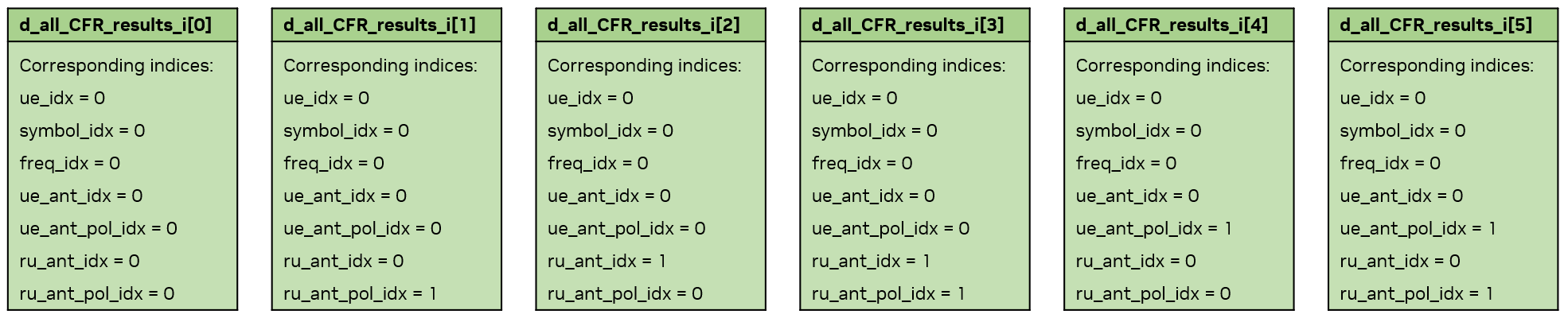
For the minimum delay results, there is one minimum delay for all RU-UE antenna pairs (i.e., one value for one RU-UE pair, and
d_all_tau_mins[i]holds the minimum delays from -th RU to its associated UEs).Similar device memory arrangements are done for
cir_values,cir_delays,angles_of_departure, andangles_of_arrivalin eachCIRResult. In the multi-time-step API, theseCIRResultobjects are stored incir_result.cir_results[time_step][ru_pos]and point into the contiguous buffers owned byMultiTimeStepCIRResult. -
runEMSolver()
Launch the EM engine.
-
copyResultsFromDeviceToHost()
Copy the results of the EM engine from device to host.
-
deAllocateDeviceMemForResults()
Deallocate device memory previously used for the EM engine results.
The first overload is the legacy single-time-step API. The second overload deallocates the contiguous CIR buffers owned by
MultiTimeStepCIRResult. -
getBuildingEdges()
Return all building edges of the scene.
Error handling
The EM engine has built-in error handling. The function where the error or invalid condition occurs is recorded and error messages are propagated to both the local console and the Console tab in the graphical interface.
-
EMLogLevel
An enumeration for the level of logging.
-
EMLogCallback
Callback function prototype.
-
registerLogCallback()
Function to register a callback function (type
EMLogCallback) for error handling. -
deregisterLogCallback()
Function to deregister the currently registered callback function.