

Controllers
Robotic tasks are typically defined in task-space in terms of desired
end-effector trajectory, while control actions are executed in the
joint-space. This naturally leads to joint-space and task-space
(operational-space) control methods. However, successful execution of
interaction tasks using motion control often requires an accurate model
of both the robot manipulator as well as its environment. While a
sufficiently precise manipulator’s model might be known, detailed
description of environment is hard to obtain :citesiciliano2009force.
Planning errors caused by this mismatch can be overcome by introducing a
compliant behavior during interaction.
While compliance is achievable passively through robot’s structure (such as elastic actuators, soft robot arms), we are more interested in controller designs that focus on active interaction control. These are broadly categorized into:
-
impedance control: indirect control method where motion deviations caused during interaction relates to contact force as a mass-spring-damper system with adjustable parameters (stiffness and damping). A specialized case of this is stiffness control where only the static relationship between position error and contact force is considered.
-
hybrid force/motion control: active control method which controls motion and force along unconstrained and constrained task directions respectively. Among the various schemes for hybrid motion control, the provided implementation is based on inverse dynamics control in the operational space :cite
khatib1987osc.
To provide an even broader set of motion generators, we welcome contributions from the community. If you are interested, please open an issue to start a discussion!
Choosing a controller
Basic joint-space control sets joint targets directly on the actuators.
For joint-space impedance control, use JointImpedanceController
(see Joint-space controllers_).
Start with differential IK for reaching or teleoperation with position-controlled actuators. Choose OSC when you need torque commands, task-space compliance, or simultaneous motion and contact force control. For example, wiping a table requires motion along its surface while maintaining a force normal to it.
The IK walkthrough and OSC walkthrough provide complete scenes, state extraction, and runnable demonstrations. Both tutorial scripts use Isaac Sim PhysX and require an Isaac Sim installation.
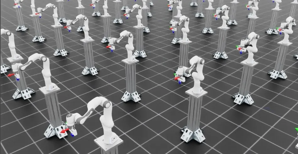
IK: reach a pose. Each arm tracks an end-effector goal through joint position targets. Run the IK demonstration to watch the measured and desired frame markers converge.
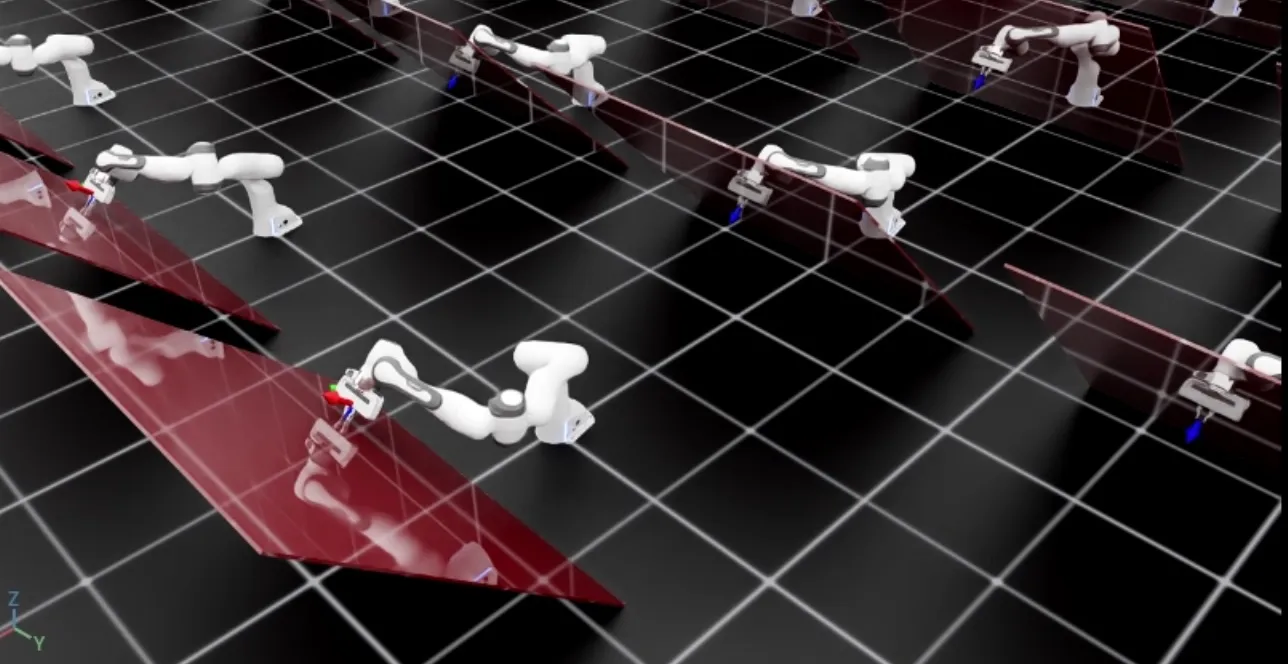
OSC: control motion and contact force. The tilted-wall example commands 10 N along the wall normal while tracking pose in the other directions. Run the OSC demonstration .
The control loop
The IK and OSC instances compute targets from state supplied by the caller;
they do not read the simulation or submit actuator commands.
~DifferentialIKController.set_command stores a goal until it is replaced,
and every control cycle reads fresh state, calls compute(), stages the targets,
and steps the simulation; see Practical API examples for the loop from the
IK walkthrough. IK targets are joint positions that the configured position
actuator tracks. OSC targets are joint efforts, so configure zero actuator
stiffness and damping to keep actuator feedback from adding to them.
Keep the command, end-effector pose, and Jacobian in a consistent coordinate frame.
The tutorials use the suffix _b for the robot base frame and _w for the
world frame; these names do not transform the data.
Absolute poses contain position followed by a quaternion in (x, y, z, w) order.
For OSC, commands and axis selections can use a separate task frame, while state
passed to compute() remains in the base frame.
Joint-space controllers
There is no dedicated configuration class for selecting a joint-space control mode. Instead, the
control mode follows from which targets you set through articulation.actuators: effort targets
for torque control, velocity targets for velocity control, and position targets for position
control. See Runtime API: articulation.actuators for the runtime API.
Torque control
Action dimensions: "n" (number of joints)
In torque control mode, the input actions are directly set as feed-forward joint torque commands, i.e. at every time-step,
Velocity control
Action dimensions: "n" (number of joints)
In velocity control mode, a proportional control law is required to reduce the error between the current and desired joint velocities. Based on input actions, the joint torques commands are computed as:
where are the gains parsed from configuration.
While performing velocity control, in many cases, gravity compensation is required to ensure better tracking of the command. In this case, we suggest disabling gravity for the links in the articulation in simulation.
Position control with fixed impedance
Action dimensions: "n" (number of joints)
In position control mode, a proportional-damping (PD) control law is employed to track the desired joint positions and ensuring the articulation remains still at the desired location (i.e., desired joint velocities are zero). Based on the input actions, the joint torque commands are computed as:
where and are the gains parsed from configuration.
A more complete formulation which considers the dynamics of the articulation would be:
where is the joint-space inertia matrix of size , and is the joint-space
gravity vector. This implementation is available through the JointImpedanceController class by setting the
impedance mode to "fixed". The gains are parsed from the input configuration and
are computed while considering the system as a decoupled point-mass oscillator, i.e.,
where is the damping ratio of the system. Critical damping is achieved for , overcritical damping for and undercritical damping for .
Additionally, it is possible to disable the inertial or gravity compensation in the controller by setting the
flags inertial_compensation and gravity_compensation in the configuration to False,
respectively.
Position control with variable stiffness
Action dimensions: "2n" (number of joints)
In stiffness control, the same formulation as above is employed, however, the gains are part of
the input commands. This implementation is available through the JointImpedanceController class by
setting the impedance mode to "variable_kp".
Position control with variable impedance
Action dimensions: "3n" (number of joints)
In impedance control, the same formulation as above is employed, however, both and
are part of the input commands. This implementation is available through the JointImpedanceController
class by setting the impedance mode to "variable".
Task-space controllers
Differential inverse kinematics (IK)
Action dimensions: "3" (relative/absolute position), "6" (relative pose), or "7" (absolute pose)
Inverse kinematics converts the task-space tracking error to joint-space error. In its most typical implementation, the pose error in the task-space, , is computed as the Cartesian distance between the desired and current task-space positions, and the shortest distance in \mathbb{SO}(3) between the desired and current task-space orientations.
Using the geometric Jacobian J_{eO} \in \mathbb{R}^{6 \times n}, that relates task-space velocity to joint-space velocities, we design the control law to obtain the desired joint positions as:
where is a scaling parameter and J_{eO}^{-} is the pseudo-inverse of the Jacobian.
It is possible to compute the pseudo-inverse of the Jacobian using different formulations:
- Moore-Penrose pseudo-inverse (
"pinv"): A^{-} = A^T(AA^T)^{-1}. - Levenberg-Marquardt pseudo-inverse (damped least-squares,
"dls"): A^{-} = A^T (AA^T + \lambda^2 \mathbb{I})^{-1}. - Transpose pseudo-inverse (
"trans"): A^{-} = A^T. - Adaptive singular-value decomposition (SVD) pseudo-inverse (
"svd") from :citebuss2004ik. - Manipulability-aware damped least-squares (
"adaptive_dls"): the damping increases as the Jacobian approaches a singularity.
These implementations are available through the DifferentialIKController class.
See ../how-to/run_diff_ik for a runnable example.
Impedance controller
It uses task-space pose error and Jacobian to compute joint torques through mass-spring-damper system with a) fixed stiffness, b) variable stiffness (stiffness control), and c) variable stiffness and damping (impedance control).
Operational-space controller
Similar to task-space impedance control but uses the Equation of Motion (EoM) for computing the task-space force. See ../how-to/run_osc for a runnable example.
Closed-loop proportional force controller
It uses a proportional term to track the desired wrench command with respect to current wrench at the end-effector.
Hybrid force-motion controller
It combines closed-loop force control and operational-space motion control to compute the desired wrench at the end-effector. It uses selection matrices that define the unconstrained and constrained task directions.
Practical API examples
Joint targets
These alternative command examples assume an initialized robot and resolved
arm_joint_ids. Each target has shape (num_envs, len(arm_joint_ids)).
Set position or velocity feedback gains in the actuator configuration; for direct
effort control, set actuator stiffness and damping to zero. See
Runtime API: articulation.actuators for the command API and actuators for gains.
Position
Velocity
Effort
These calls stage and submit commands. Advance physics and update the scene on each cycle as shown in The control loop.
Task-space goals
The IK walkthrough resets the robot and changes the goal every 150 steps. On intermediate steps, it reads fresh state and computes joint position targets; every step applies the targets and advances the simulation:
Relative commands also need the measured pose in
DifferentialIKController.set_command to resolve the delta at command time.
An OperationalSpaceController instance osc similarly stores its
motion/force goal with OperationalSpaceController.set_command, but
OperationalSpaceController.compute returns efforts to stage with
set_effort_index. Its required state depends on the configured features.
Use the IK walkthrough and
OSC walkthrough for controller construction, state
extraction, and complete repeated loops.
Reactive planners
Typical task-space controllers do not account for motion constraints such as joint limits, self-collision and environment collision. Instead they rely on high-level planners (such as RRT) to handle these non-Euclidean constraints and give joint/task-space way-points to the controller. However, these methods are often conservative and have undesirable deceleration when close to an object. More recently, different approaches combine the constraints directly into an optimization problem, thereby providing a holistic solution for motion generation and control.
Examples of reactive planners include:
-
RMPFlow (lula): An acceleration-based policy that composes various Reimannian Motion Policies (RMPs) to solve a hierarchy of tasks :cite
cheng2021rmpflow. It is capable of performing dynamic collision avoidance while navigating the end-effector to a target. -
MPC (OCS2): A receding horizon control policy based on sequential linear-quadratic (SLQ) programming. It formulates various constraints into a single optimization problem via soft-penalties and uses automatic differentiation to compute derivatives of the system dynamics, constraints and costs. The MPC formulation for end-effector trajectory tracking in fixed-arm and mobile manipulators described in :cite
mittal2021articulatedconsiders a kinematic system model with joint limits and self-collision avoidance. See the OCS2 documentation for the external toolbox and examples.
limit throughput in large batches. It also needs the Lula library and robot description files; these dependencies are separate from the selected physics backend.