UEFI Platform Vendor Key Feature#
The UEFI platform vendor (PV) key feature allows PVs to deploy UEFI that is signed and encrypted by PV-owned keys without involving the solution providers.
- NVIDIA® Jetson™ devices use a PKC key to verify the signature of boot component during device boot:
The component at stage N verifies the components at stage N+1.
The component at stage N+1 verifies the components at stage N+2, and so on.
With this feature, the UEFI owner, or the PV, can use a PV’s private key to sign UEFI, and can also deliver the public key to the solution provider, who was the owner of the boot components before UEFI. The public key is now built into the component (MB2) that loads in UEFI during boot.
During the secure boot process, the signature of the components before UEFI will be verified/authenticated by solution provider’s fused PKC. For UEFI, MB2 uses the built-in public key to verify PV authenticate key for key verification and signature authentication. As a result, the platform vendor, who does not own the fused PKC, can still independently sign and update the UEFI image.
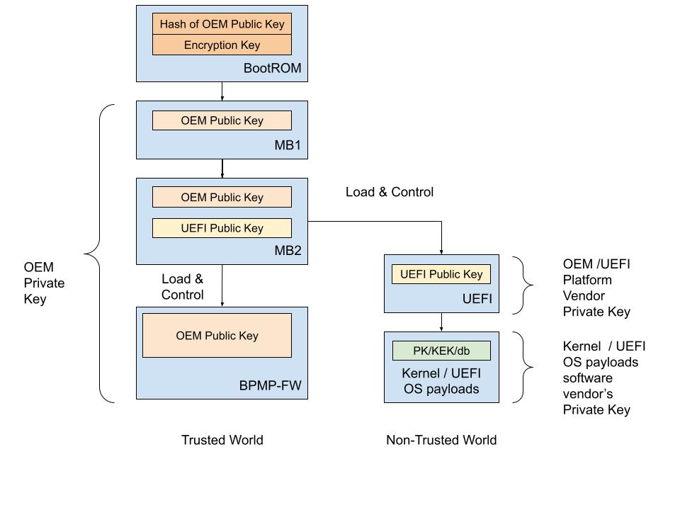
In Jetson devices that use the T234 processor (NVIDIA® Jetson Orin™ NX series and NVIDIA® Jetson AGX Orin™ series) and T264 processor (NVIDIA® Jetson Thor series), the PV key sign/authenticate UEFI is supported when Secure Boot is enabled.
Platform Vendor Key Sign/Authenticate UEFI#
This section describes how to use a tool to sign UEFI by the PV and to authenticate it by the solution provider.
The PV can sign UEFI by the key it owns. Here is a high-level overview of the process:
The PV provides the PV authentication key file to the solution provider.
The solution provider builds boot images with the PV authentication key that is built into MB2.
The solution provider sends the results from step 2 to the PV.
The PV creates the combined boot images and completes one of the following tasks:
Sends the images to the factory floor to build the device.
Sends the images to the OTA server for the update.
Before you enable UEFI PV key sign/authenticate feature, the RSA 3K authentication scheme fuse must be burned.
Note
RSA-3072, ECDSA-P256, ECDSA-P521 are supported for UEFI PV key signing.
The cryptography algorithm of the UEFI PV key should be aligned with the PKC key used for signing low-level boot components.
Platform Vendor Procedure#
Jetson AGX Orin#
To generate the PV authentication key and sign UEFI:
Generate the PV key pair and call it
pv_priv.pem:To generate an ECDSA P-256 key:
$ openssl ecparam -name prime256v1 -genkey -noout -out pv_priv.pem
To generate an ECDSA P-521 key:
$ openssl ecparam -name secp521r1 -genkey -noout -out pv_priv.pem
To generate an RSA-3K key:
$ openssl genrsa -out pv_priv.pem 3072
Create a certificate signing request and call it
pub_key.csr:$ openssl req -key pv_priv.pem -new -out pub_key.csr
Create a self-signed certificate and call it
pv_key.crt:$ openssl x509 -signkey pv_priv.pem -in pub_key.csr -req -days 3650 -out pv_key.crt
Provide the
pv_key.crtfile to the solution provider.Get
bootloader.tar.gzfrom the solution provider as described in the solution provider procedure for Jetson AGX Orin, place it in theLinux_for_Tegra/folder, and untar it:$ tar -xzvf bootloader.tar.gz
Gather the
BOARDID,FAB,BOARDSKU, andBOARDREVenvironment information from the solution provider.Generate the signed UEFI image with the PV private key:
$ sudo BOARDID=<board_id> FAB=<fab> BOARDSKU=<sku_number> BOARDREV=<reversion> ./flash.sh --no-flash -u pv_priv.pem -k A_cpu-bootloader jetson-agx-orin-devkit internal
Flash the device with the following commands:
$ boardctl -t topo recovery
$ cd bootloader/
$ sudo bash ./flashcmd.txt
Jetson AGX Thor#
To generate the PV authentication key and sign UEFI:
Generate the PV key pair and call it
pv_priv.pem:To generate an ECDSA P-256 key:
$ openssl ecparam -name prime256v1 -genkey -noout -out pv_priv.pem
To generate an ECDSA P-521 key:
$ openssl ecparam -name secp521r1 -genkey -noout -out pv_priv.pem
To generate an RSA-3K key:
$ openssl genrsa -out pv_priv.pem 3072
Create a certificate signing request and call it
pub_key.csr:$ openssl req -key pv_priv.pem -new -out pub_key.csr
Create a self-signed certificate and call it
pv_key.crt:$ openssl x509 -signkey pv_priv.pem -in pub_key.csr -req -days 3650 -out pv_key.crt
Provide the
pv_key.crtfile to the solution provider.Gather the
BOARDID,FAB,BOARDSKU,BOARDREV,RAMCODE_ID, andCHIP_SKUenvironment information from the solution provider.Generate the signed UEFI image with a PKC key list XML file such as
t264_pv_key_list.xml. For the format oft264_pv_key_list.xml, refer to Generate a PKC Key List for Jetson Thor:$ sudo UNIFIED_FLASH=0 BOARDID=<board_id> FAB=<fab> BOARDSKU=<sku_number> BOARDREV=<reversion> RAMCODE_ID=<ramcode_id> CHIP_SKU=<chip_sku> ./tools/kernel_flash/l4t_initrd_flash.sh --no-flash -u t264_pv_key_list.xml -k A_cpu-bootloader jetson-agx-thor-devkit internal
Back up the generated UEFI image
bootloader/uefi_t26x_general_with_dtb_aligned_blob_w_bin_sigheader.bin.signedfor later use.Get the package that contains
output/andunified_flash/from the solution provider as described in the solution provider procedure for Jetson AGX Thor, place it in theLinux_for_Tegra/folder, and untar it.Replace
unified_flash/out/bsp_images/flash_workspace/flash-images/uefi_t26x_general_with_dtb_aligned_blob_w_bin_sigheader.bin.signedwith the backed-up UEFI imageuefi_t26x_general_with_dtb_aligned_blob_w_bin_sigheader.bin.signed.Use
md5sumto obtain the MD5 value of the updated UEFI image, and update the MD5 field for the UEFI image entry inoutput/FileToFlash.txt.Flash the device:
$ sudo UNIFIED_FLASH=1 ./l4t_initrd_flash.sh --flash-only
Solution Provider Procedure#
Jetson AGX Orin#
After the solution provider receives the PV authentication key, to enable the PV sign/authenticate UEFI feature, complete the following steps:
Place the
pv_key.crtfile in theLinux_for_Tegra/folder.Generate the signed boot images with the board-fused PKC key file (
pkc.pem) and the PV key certificate (pv_key.crt):$ sudo BOARDID=<board_id> FAB=<fab> BOARDSKU=<sku_number> BOARDREV=<reversion> ./flash.sh --no-flash -u pkc.pem --pv-crt pv_key.crt jetson-agx-orin-devkit internal
Package the
Linux_for_Tegra/bootloader/folder:$ tar -czvf bootloader.tar.gz ./bootloader
Send the
bootloader.tar.gzfile to the PV.
Jetson AGX Thor#
After the solution provider receives the PV authentication key, to enable the PV sign/authenticate UEFI feature, complete the following steps:
Place the
pv_key.crtfile in theLinux_for_Tegra/folder.Generate the signed boot images with a PKC key list XML file such as
t264_key_list.xmland the PV key certificate (pv_key.crt). For the format oft264_key_list.xml, refer to Generate a PKC Key List for Jetson Thor:$ sudo BOARDID=<board_id> FAB=<fab> BOARDSKU=<sku_number> BOARDREV=<reversion> RAMCODE_ID=<ramcode_id> CHIP_SKU=<chip_sku> ./l4t_initrd_flash.sh --no-flash -u t264_key_list.xml --pv-crt <pv_crt> jetson-agx-thor-devkit internal
Package
output/andunified_flash/and send them to the platform vendor.
PV Key Encrypt/Decrypt UEFI (Only for Jetson Orin Series)#
This section describes how to use the tool to encrypt UEFI by using a key owned by the PV and to decrypt it by the solution provider at MB2.
The mechanism is that the key encrypts UEFI is the PV-owned encryption key instead of the default SBK key. The PV will encrypt UEFI with its owned PV encryption key in one of the following ways:
The PV provides a fuse blob so that the PV encryption key can be burned into the fuse.
The PV provides the PV encryption key to the solution provider who can then inject the key into MB2 by using the tool.
Before enabling the UEFI PV key encrypt/decrypt feature, the SBK key and the encryption mode fuse must be burned. Refer to Fuse handling for more information.
Fuse Solution#
To provide a higher level of protection to the PV encryption key, the PV can burn the PV encryption key into the OEM_K2 fuse. Now, MB2 can decrypt PV encrypted UEFI by using OEM_K2 through Security Engine without knowing the actual key, and here are the decryption steps:
The PV generates a fuse blob, which includes the PV encryption key, and that will be burned into OEM_K2 fuse.
The PV encrypts the UEFI image with the PV encryption key.
The solution provider generates its own fuse blob that includes the SBK key fuse and the encryption mode enable fuse.
The solution provider builds the boot images with the SBK key.
The solution provider sends the results from steps 3 and 4 to the PV.
The PV generates UEFI image, combines the boot images generated by the solution provider and the encrypted UEFI image generated by PV, and completes one of the following tasks:
Sends the images to the factory floor to build the device.
Sends the images to the OTA server for the OTA update.
Note
To increase security level, the PV encryption key in this procedure is used to derive a final key for UEFI image encryption and decryption.
Platform Vendor Procedure#
This procedure generates the PV encryption key, generates the signing PV key, and encrypts and signs UEFI:
Generate the AES-256 key and call it
pv_enc.key:$ openssl rand -hex 32 > pv_enc.key
Manually reformat
pv_enc.keyinto eight 32-bit words big-endian hexadecimal.For example, original content of
pv_enc.keyis112233445566778899aabbccddeeff00ffeeddccbbaa99887766554433221100, and after the reformat, it changes to0x11223344 0x55667788 0x99aabbcc 0xddeeff00 0xffeeddcc 0xbbaa9988 0x77665544 0x33221100.Generate the PV private key and its certificate.
Follow the same key generation steps as described in Platform Vendor Procedure (steps 1-4).
Note
If the PV signing key and its certificates have been previously generated, you can skip this step.
Get
bootloader.tar.gzfrom the solution provider, place it in the Linux_for_Tegra/, and untar it:$ tar -xzvf bootloader.tar.gz
Gather the BOARDID, FAB, BOARDSKU, and BOARDREV environment information from the solution provider.
Generate the signed and encrypted UEFI image with the PV private key (
pv_priv.pem) and the PV encryption key (pv_enc.key):$ sudo BOARDID=<board_id> FAB=<fab> BOARDSKU=<sku_number> BOARDREV=<reversion> ./flash.sh --no-flash -u pv_priv.pem --pv-enc pv_enc.key -k A_cpu-bootloader jetson-agx-orin-devkit internal
Get the fuse blob from the solution provider and provide the solution provider’s fuse blob and the PV’s fuse blob to the factory to burn fuses.
Burn the fuse.
Run the following commands to flash the device:
$ boardctl -t topo recovery
$ cd bootloader/
$ sudo bash ./flashcmd.txt
Solution Provider Procedure#
After the solution provider receives the PV authentication key, complete the following steps:
Place the
pv_key.crtfile in the same folder as the flash.sh script.Generate the signed and encrypted boot images by using the PKC key (
pkc.pem), the SBK key, and the PV authentication key certificate (pv_key.crt):$ sudo BOARDID=<board_id> FAB=<fab> BOARDSKU=<sku_number> BOARDREV=<reversion> ./flash.sh --no-flash -u pkc.pem -v <sbk.key> --pv-crt pv_key.crt jetson-agx-orin-devkit internal
Package the Linux_for_Tegra/bootloader/ folder:
$ tar -czvf bootloader.tar.gz ./bootloader
Send the
bootloader.tar.gzfile to the PV.
Fuse handling#
Before you execute the above flashing command, the device fuses must be burned with the fuse blobs that are provided by the PV and the solution provider.
Here is an example of a fuse blob (1) provided by the PV:
<genericfuse MagicId="0x45535546" version="1.0.0">
    <fuse name="PscOdmStatic" size="4" value="0x00000060"/>
    <fuse name="OemK2" size="32" value="0x112233445566778899aabbccddeeff00ffeeddccbbaa99887766554433221100"/>
</genericfuse>
Here is an example of a fuse blob (2) provided by the solution provider:
<genericfuse MagicId="0x45535546" version="1.0.0">
    <fuse name="PscOdmStatic" size="4" value="0x00000060"/>
    <fuse name="OemK1" size="32" value="0xf3bedbff9cea44c05b08124e8242a71ec1871d55ef4841eb4e59a56b5f88fb2b"/>
    <fuse name="PublicKeyHash" size="64" value="0xdc6632e495c7976659a94668a98d6ba7e22a2d9438a555ec64c0c1cc59e533067bfe64f454c1f30c63ad7627fb0cfa2f556aff45818254387016745ccf713081"/>
    <fuse name="SecureBootKey" size="32" value="0x123456789abcdef0fedcba987654321023456789abcdef01edcba9876543210f"/>
    <fuse name="BootSecurityInfo" size="4" value="0x209"/>
    <fuse name="SecurityMode" size="4" value="0x1"/>
</genericfuse>
You must ensure that in the fuse burning sequence, the fuse blob 1 is burned first.
Note
The fuses specified in the PV’s fuse blob and the fuses specified in solution provider cannot be overlapped.
The fuse blob provided by the PV must be burned first because, after the “SecurityMode” that is specified in the solution provider’s fuse blob is burned, fuse burning except ODM fuses is blocked.
The above fuse values in both PV and solution provider’s fuse blobs are for demonstrations only.