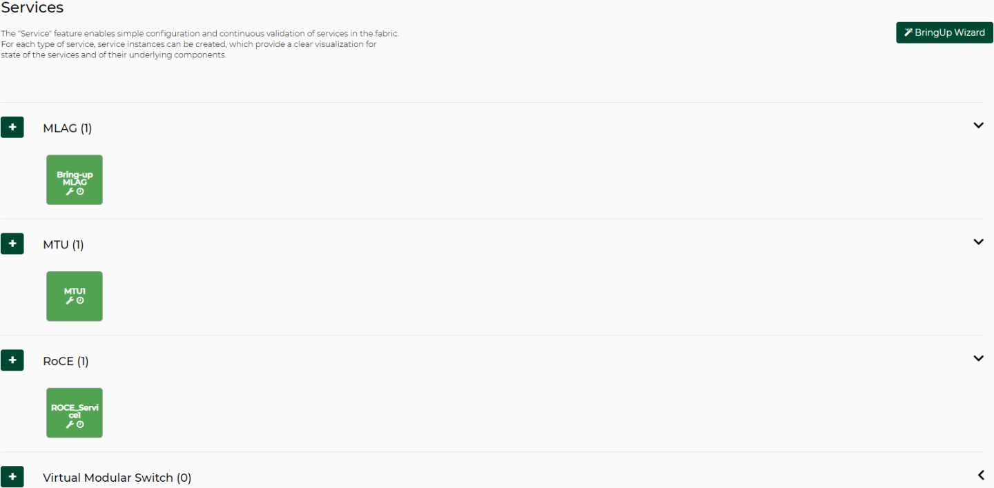
Services
The Services window enables simple configuration and continuous validation of services in the fabric. For each type of service, service instances can be created providing a clear visualization for the state of the services and their underlying components. A bring-up wizard can further simplify the configuration of the network by allowing the user to provide in a few minimal steps all the input required for bringing up the network from scratch.
The five available service types are:
Bring Up
Virtual Modular Switch
VMS
L3 Network Provisioning
MLAG
MTU
RoCE
The service types and configurations are divided in the Service view as seen in the figure above, and an Add button, as well as a help button, are available for each one of them.
The configuration and cleanup commands generated for the services assume that the switches have no prior configuration. Prior configuration may cause some of the commands to fail and lead to inconsistent configuration on the switches.
NEO enables a quick network bring-up that includes all the required configurations in one easy process. The user should only provide minimal input for the type of configurations needed in the bring-up wizard. All configuration steps are optional. Clicking “BringUp Wizard” will open the wizard for user input.
The wizard works on Onyx switch systems.
A configuration snapshot is taken for the devices participating in the bring-up before any configuration is done. This snapshot can be used to revert all the bring-up configuration changes.
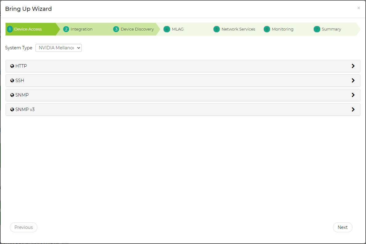
Device Access
In this tab, the user can fill out the Device Access information for the device types participating in the bring-up.
This updates the global credentials for the selected system type.
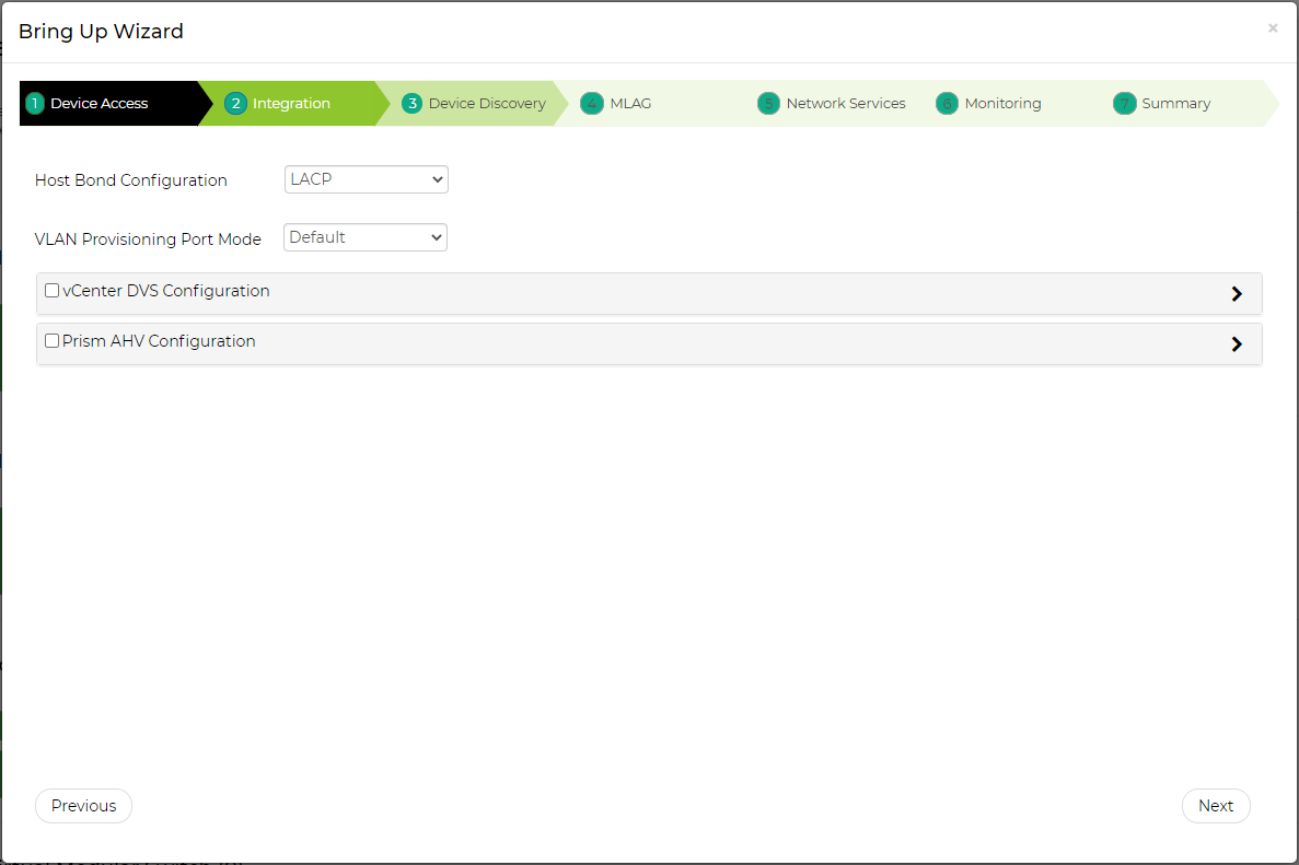
Integration
In this tab, the user can define integration with various hypervisors. This new capability helps NEO acquire information about the VMs running on them and handle VM lifecycle events to properly configure VLAN on the switches.
Host Bond Configuration – the user can select the type of bonds that are being used on the hosts. If LACP bond configuration is used, NEO will suggest to create MPOs (see MLAG Port Channels) according to the links it detected on the switches.
VLAN Provisioning Port Mode – the user can select which port mode to assign to the switch ports or MPOs (according what the user selected in the Host Bond Configuration section mentioned above). The options are hybrid, trunk, or default (which is to let NEO use the current switch port mode configuration). This is used when using NEO to handle VM lifecycle events and change switch VLAN configuration accordingly.
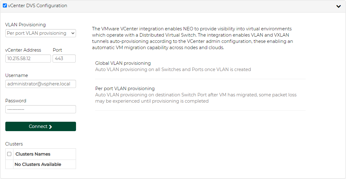
VMware vCenter DVS Configuration
In this section the user can define VMware vCenter connectivity information. NEO uses it to get information from the vCenter regarding VM information and lifecycle events.
The VLAN Provisioning drop down contains the following options:
Disabled – VM lifecycle events will not be handled. NEO will only retrieve VM information from vCenter.
Global VLAN provisioning – NEO will listen to network events. In case of a network change event (e.g. adding or removing a network), NEO will add or remove VLANs to/from all switch ports. VLANs will be removed from the ports but will not be removed from the switch.
WarningThis is the recommended VLAN provisioning mode when working with Live Migration.
In this mode, the VLANs' auto-provisioning is performed upon network creation (before the VM migration event) therefore, it prevents traffic lose.
Per port VLAN provisioning – NEO will listen to VM lifecycle events. In case of a VM change (e.g. VM added, removed or migrated) which required changes in VLANs, NEO will add or remove the VLAN accordingly from the relevant switch ports.
Upon filling the vCenter IP address, port, username and password, the user should click the Connect button to make sure the details are correct and NEO can connect the vCenter. If the connection is successful, a list of clusters managed by the vCenter will be shown in the Clusters table. The user should check the clusters he/she wants NEO to manage.
The Connect button should be clicked after every change so the new information will be processed by NEO.
Nutanix Prism AHV Configuration
In this section the user can define the Nutanix Prism Central and the Prism Element connectivity information. NEO uses it to get information from Prism regarding devices, VM information and lifecycle events. For further information, refer to NEO-Nutanix Prism Plug-in.
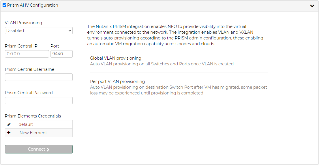
The VLAN Provisioning drop down contains the following options:
Disabled – VM lifecycle events will not be handled. NEO will only retrieve VM information from vCenter.
Global VLAN provisioning – NEO will listen to network events. In case of a network change event (e.g. adding or removing a network), NEO will add or remove VLANs to/from all switch ports. VLANs will be removed from the ports but will not be removed from the switch.
WarningThis is the recommended VLAN provisioning mode when working with Live Migration.
In this mode, the VLANs' auto-provisioning is performed upon network creation (before the VM migration event) therefore, it prevents traffic lose.
Per port VLAN provisioning – NEO will listen to VM lifecycle events. In case of a VM change (e.g. VM added, removed or migrated) which required changes in VLANs, NEO will add or remove the VLAN accordingly from the relevant switch ports.
Prism Central - IP, port, username and password are used to connect to the Prism Central. In case of working without Prism Central, put the Prism Element details instead.
Prism Elements Credentials – here the user should fill the username and passwords of each Prism Element in the network. Use “default” to fill the same credentials to all Prism Elements or specify credentials per Prism Element IP.
Upon filling the Prism Central IP address, port, username and password, and the Prism Element credentials, the user should click the Connect button to make sure the details are correct and NEO can connect the Prism. If the connection is successful, the switches and Nutanix hosts known to Prism will be added to NEO. This might take a couple of minutes.
WarningThe Connect button should be clicked after every change so the new information will be processed by NEO.
When enabling VLAN provisioning, the user can also set some advanced properties that affect the communication with Prism.
Device Discovery
In this tab, the user can fill out the switches needed to be configured. The switches are organized in pairs, so MLAG can be created from each pair. NVIDIA ® NEO ® can automatically detect MLAG switch pairs that fulfill the connectivity prerequisites and move them to the “Selected” table.
MLAG configuration may be skipped by using the "Proceed without MLAG configuration" checkbox, and selected devices can be configured with MTU and ROCE in the Network Services step.
If the switches are not listed, the user can click “Add Device” and add them.
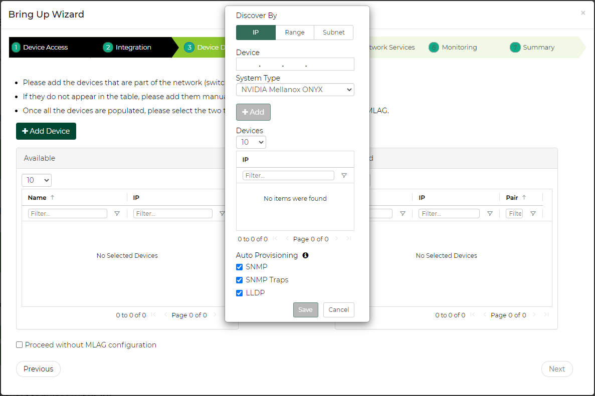
Devices can be added by their management IP address (click the

button to add them to the list). When done, click the “Add Devices” button. In case only one switch is known by NEO, NEO will try to discover switches linked to this switch using LLDP. If you want to use this ability, please make sure that LLDP protocol is enabled on your switches. once LLDP results are retrieved, relevant switch IP will be automatically populated.

Alternatively, the user can specify a range of IPs or subnet IP to scan (see also Discovery Settings) and click the "Save and Scan" button to start scanning.


After adding the devices in any of the above methods, they will undergo a short discovery cycle to get the required data and then will be available for the bring-up.
MLAG
The MLAG tab defines the necessary information for MLAG configuration in the selected switch pair.
The MPO VLAN field allows the user to add VLANs (networks) to all switch pairs in one click.
The MPO switchport mode field sets the default switchport mode that will be used for MPOs defined in each MLAG pair. The user can change specific MPOs to other values if necessary.
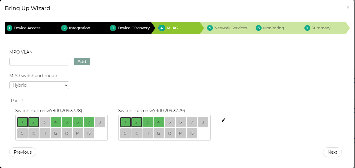
For each pair, the user can select the ports that will be part of the MLAG IPL. The ports that NEO identified as linking the two switches are automatically selected. Clicking the

button will allow the user to set other MLAG related attributes.
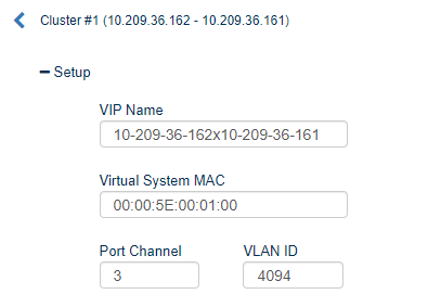
Setup
This section defines MLAG attributes:
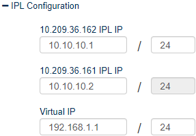
IPL Configuration
This section defines MLAG IPL attributes:
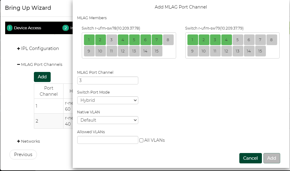
MLAG Port Channels
This section defines MPOs to configure on the switch. If you are using LACP bond mode configuration, NEO will auto-populate the table with any host linked to both switches in the pair.

The user can add or change MPOs according to the required network configuration.
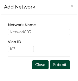
Networks
This section defines layer 2 networks (VLANs) to configure on the switch. A default network with VLAN 1 is automatically added and is the default for MLAG port channel native VLAN definition.
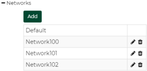
Add a network by clicking the “Add” button and setting its name and VLAN ID:
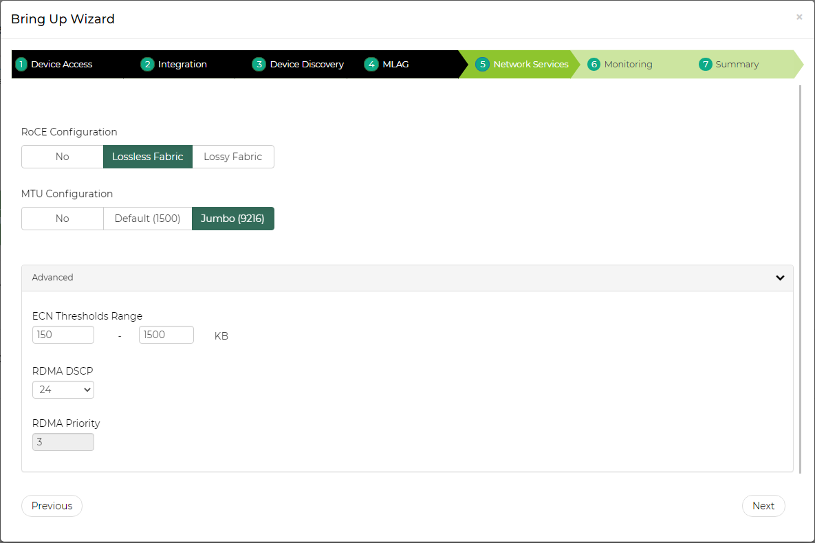
Network Services
In this tab, the user can specify RoCE and MTU definitions. If RoCE is required, the user can define in the advanced section ECN thresholds and the priority to use for RoCE traffic.
Monitoring
In this tab, the user can define the telemetry means for monitoring the network configuration and traffic behavior. In the top section, the user can decide whether or not to deploy the telemetry agent on the switches (top checkbox), and if so, which telemetry sessions to use.
For more information on Telemetry Agent and Sessions see Telemetry Streaming.
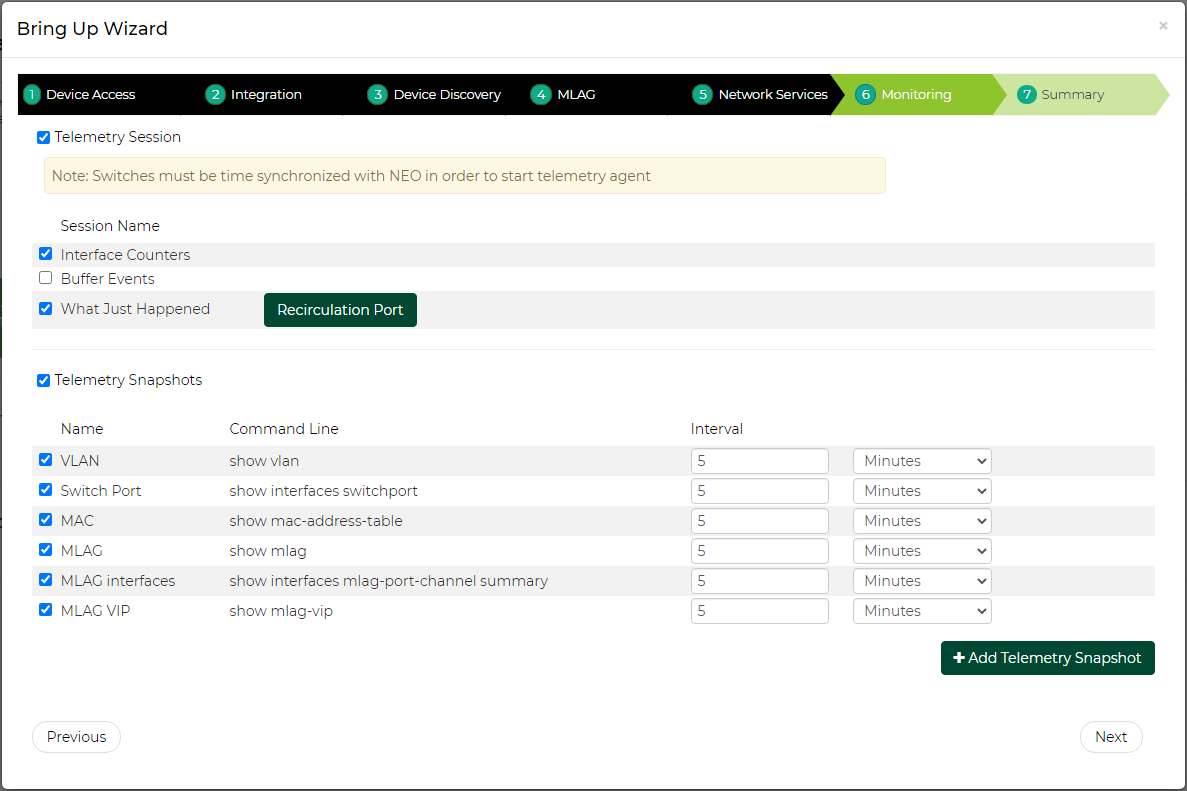
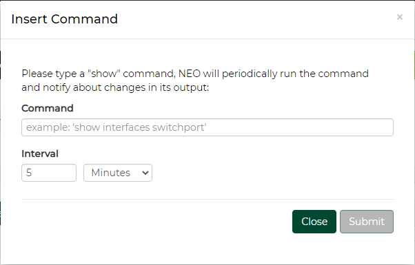
In the bottom section, the user can select which telemetry snapshots to enable. These will run a show command periodically and the user will be notified when the output will change. Clicking “Add Telemetry Snapshot” allows the user to add his own show command:
Summary
In this tab, the user can see a summary of all the definitions that are going to be configured on each switch pair.
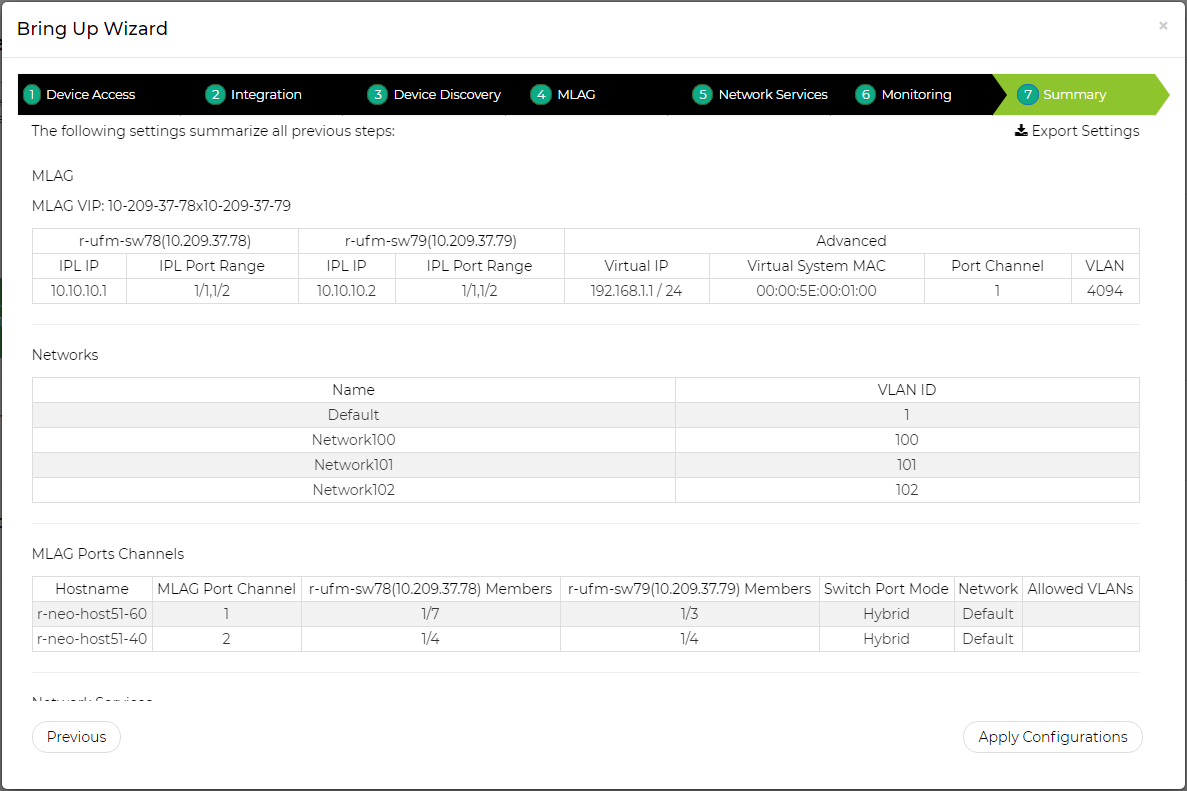
Clicking “Apply configuration” will start the configuration process, which can take a couple of minutes. You can track the progress in the bring-up progress dialog and in the jobs page. For MLAG, RoCE and MTU configurations, service objects will be created and used to apply the required configuration on the switch pairs (see section .Services v2.7.10#Service Elements for more information). Telemetry actions (agent deployment and session configuration) will be done after the services are configured.
In case the MLAG configuration failed, the bring-up will not continue to the next phases. After failures in other phases NEO will try to continue with the bring-up process.
Virtual Modular Switch
A drop-down menu will appear, allowing the user to select two types of services when clicking the "+" button:

VMS
Before setting up VMS using the NEO VMS service, it is highly recommend to review the information and prerequisites found in Virtual Modular Switch™ Reference Guide.
NVIDIA's Virtual Modular Switch (VMS) solution, comprised of NVIDIA10GbE, 40GbE, and 56GbE fixed switches, provides an ideal and optimized approach for a fixed switch aggregation. VMS is energy efficient and scales up to 28.8Tb/s of non-blocking bandwidth and up to 720 nodes of 40GbE and operates at ultra-low latencies. The VMS can be set up in Layer 3 mode (L3-VMS) based on OSPF. VMS configuration and bring-up can be fully automated, from the early planning stages until it is operational, by leveraging the VMS Wizard. The VMS Wizard provides an automation environment to provision the fabric with a centralized application, an application that learns the way the switches interconnect and how they ought to operate in the data center. Once the fabric size is defined and the types of switches in the fabric are selected, the VMS Wizard specifies how to configure the switches. After installation, the wizard verifies the connectivity and applies the configuration to the switches.
In order to configure the VMS solution:
Click the “Add” button on the left side of the VMS row.
Type the service name and description under “General”.

Select the number of tiers (VMS Levels – 2 or 3).WarningFor 2 levels only (Spines and TORs), select 2. For 3 levels (TORs, Leafs and Spines), select 3.
Unlike the 2 levels choice, if you select 3 levels, you will be given more options, as can be seen in the figure below. You will also be requested to fill out the Leafs tab.
Link width from top of rack – The number of cables from each TOR to Leaf
Uplink from top of rack – The number of Leafs connected to each TOR
Link width from Leafs – The number of cables from each Leaf to Spine
WarningFor further information on the VMS topology, you may refer to the VMS Reference Guide at www.mellanox.com, under Products -> Ethernet Switch Systems -> VMS.
Select the switch members of Spines after choosing the number of ports. The available options for this tier are 12 and 36 ports. For further information on these options, please refer to "Supported Switches per Tier".

Supported Switches per Tier
Number of Ports
Switch Family
Supported Tier/s
12 ports
MSN2100
TOR/Leaf/Spine
32 ports
MSN2700, MSN3700
TOR/Leaf/Spine
48+8 ports
MSN2410
TOR
Select the switch members of Leafs after choosing the number of ports. The available options for this tier are 12 and 32 ports. For further information on these options, please refer to .Services v2.7.10#Supported Switches per Tier.

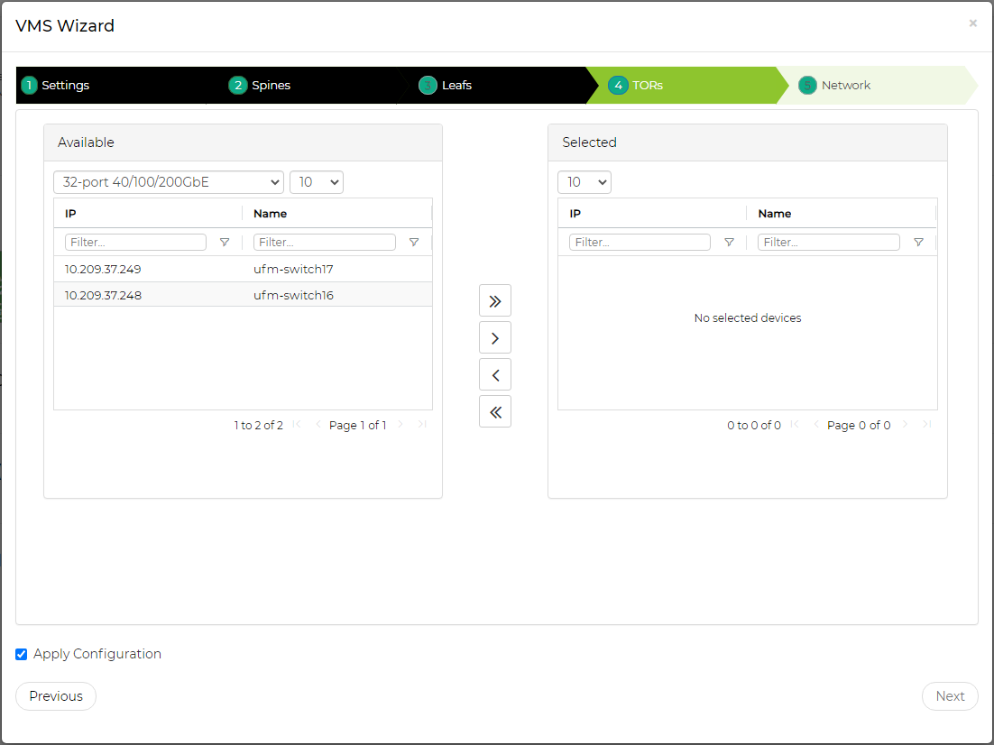
Select the switch members for TORs after choosing the number of ports. The available options for this tier are 12, 32, and 48+12 ports. For further information on these options, please refer to "Supported Switches per Tier".
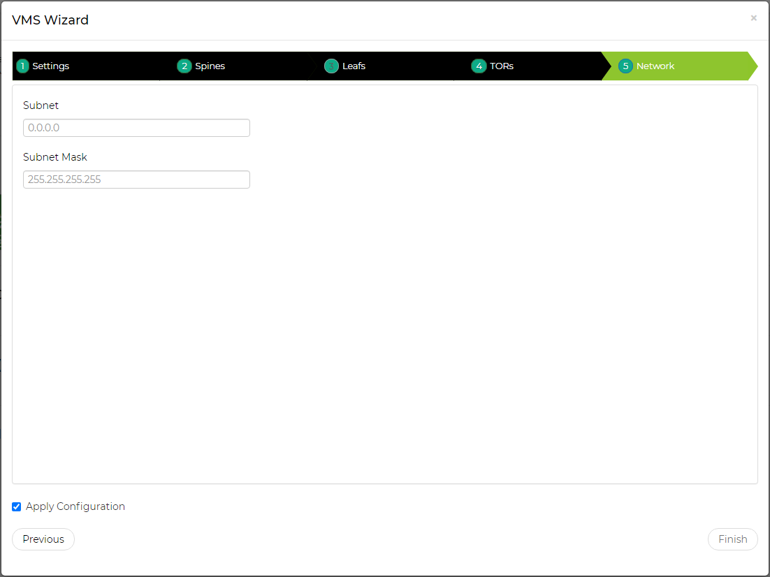
Fill in the “Network” and “Subnet Mask” fields, then click “Finish”.
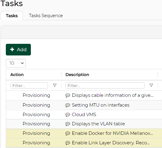
Once clicked “Finish”, a service instance will be created and a service element will appear on the Services main page. A right click on a service element will enable performing different operations. For information on the operations and the service instances in general, please refer to “Service Elements”. A task for the VMS configuration will also be created when clicking “Finish”, as described in the step below.
A task that contains all the VMS configurations to all switches will be created. Right-click the task and select “Run” to configure all the switches that are part of the VMS.
 Warning
If the selected switches are not connected as a fat tree, NEO will not create the task and will send an error message.
In order to delete a configured VMS service:
Right-click your configured VMS icon and click "Delete".
Click OK when prompted by the confirmation message.
L3 Network Provisioning
The L3 network provisioning service provides a simple provisioning capability for configuring the layer 3 network connectivity. This can be done by selecting the NVIDIAswitches and defining their IP subnet for inter-switch connectivity. The service will then discover all links between these switches and will allocate a subnet of the length of 30 for each link pair from the subnet provided by the user.
In order to configure the L3 network provisioning service, follow the steps below:
Click the “Add” button on the left side of the Virtual Modular Switch row.
Fill in the required information and check the desired checkboxes under the General dialog box:
Provide a name and description of the service.
Then in the OSPF Subnet Reservation field, type the subnet used for allocating IP addresses to OSPF areas.
[Optional] When the “Add Auto-Discovered Switches” checkbox is checked, a notification will be generated, notifying the user of a topology change in the newly created topology/service. For further information, refer to “Notifications”.
[Optional] Check the “Release Unused Resources” checkbox for unused links to be deallocated within the timeout interval chosen in minutes (the minimum is 15 minutes).
[Optional] Check the “Auto Configure Switches When Topology Changed” checkbox for auto configuration of devices upon topology changes. When this checkbox is checked, no notification will be generated. Rather, an event will appear under “Events”.

Choose the devices to configure the L3 network provisioning service for, and click “Finish”.

Once clicked “Finish”, a service instance will be created and a service element will appear on the Services main page. A right click on a service element will enable performing different operations. For information on the operations and the service instances in general, please refer to “Service Elements”.
MLAG
The MLAG service allows configuring a pair of NVIDIA ® Onyx ® or Cumulus switches with the following to support multi-chassis LAGs and periodically validates their configuration:
Switch cluster
MAGP router and network
MLAG port channel
Host bond
In order to configure the MLAG service:
Click the “Add” button on the left side of the MLAG row.
In the Cluster tab, select the switch type and IP of the first switch in the cluster. The rest of the fields (including the collapsible Advanced section) will be filled out automatically, with the option to be edited. Note that some fields might not be filled in case there is no appropriate peer switch.
WarningThe information in the Cluster tab is mandatory for the creation of the MLAG service, and cannot be changed once the service is created.

Under Networks tab, you can manage MAGP networks on the MLAG cluster. Click “Add” to add a new network and fill in the required information, or edit/delete a network using the icons in the rightmost column of the network row.
WarningNetworks are not mandatory for the MLAG service creation. They can be added, edited or removed after the service has been created.

Under Servers tab, you can manage the connectivity between the MLAG switches and the Linux hosts the MLAG switches are connected to. This includes both switch side configuration and (optionally) the host side bond creation. When first accessing this tab, it will be initialized with connected servers that NEO has already identified. Click “Add” to add a new server and fill in the required information, or edit/delete a server using the icons in the rightmost column of the server row.
WarningServers are not mandatory for the MLAG service creation. They can be added, edited or removed after the service has been created. However, if you define a server, you also need to define the network it belongs to in the Networks tab.

Once clicked “Finish”, a service instance will be created and a service element will appear on the Services main page. A right click on a service element will enable performing different operations. For information on the operations and the service instances in general, please refer to “Service Elements”.
When NEO discovers an MLAG configured on the switches, it will automatically create a service for it.
MTU
The MTU service allows configuring an interface MTU on specified Onyx switches to a desirable value and periodically validates their configuration.
In order to configure the MLAG service:
Click the “Add” button on the left side of the MTU row.
Fill in the name, description, and MTU fields.

Choose the device to configure the MTU service for, and click “Finish”.

Once clicked “Finish”, a service instance will be created and a service element will appear on the Services main page. A right click on a service element will enable performing different operations. For information on the operations and the service instances in general, please refer to “Service Elements”.
RoCE
RDMA over Converged Ethernet (RoCE) is a network protocol that allows remote direct memory access (RDMA) over an Ethernet network. It is mainly useful for network-intensive applications like networked storage or cluster computing, which require a network infrastructure with high bandwidth and low latency.
RoCE can be configured in the following configuration types: ECN only, ECN with QoS, and ECN with QoS and PFC.
To allow the network to use RoCE, both switches and hosts should be configured appropriately. The service allows one of the following modes to specify the devices to configure:
All host ports - configures all network starting from the hosts’ ports, through their directly linked switch ports, and including ports interconnecting switches.
All switch ports - configures all ports and LAGs on all network switches applicable for RoCE. Does not include host ports.
Custom selection - allows the user to specifically define which devices will be configured. If this option is selected, the wizard will include another step to define the devices. Each device can be defined as:
Host - In this mode you select the specific host interfaces that you wish to configure. These interfaces must be linked to a supported switch. The switch interfaces that are directly connected to the host interfaces will also be configured.
Switch - In this mode you select the specific switch interfaces that you wish to configure. These can also be LAGs or MLAGs.
In both modes you can select the "Configure inter-switch links" option to configure all the switch interfaces that are connected to the selected devices. For example, if you specify the leaf switches and select this option, the interfaces that connect the leaf switches to the spine switches or between different spine switches will also be configured.
For Windows hosts, the interface connectivity is not automatically detected. Therefore, the switch interfaces that are directly connected to the host interfaces will not be implicitly configured, and the "Configure inter-switch links" option is not relevant. You must explicitly create another RoCE service for the switch ports you wish to configure. This is relevant in case you select the "all host ports" option, or define hosts in the "Custom selection" option.
Editing RoCE Service
If you have specified the configured devices explicitly, using the "Custom selection" option, you can edit the RoCE service to add or remove devices and interfaces to/from your configuration. However, you will not be able to change the network configuration type, the configuration parameter values or the device type to be configured (host/switch).
Removing a switch interface does not remove the RoCE configuration that is already assigned to it until the user applies the changes.
Requirements
Before configuring RoCE using NEO, make sure your network fulfills the following requirements:
Host
The host should have a ConnectX-4 or ConnectX-5 NIC installed.
The host should have NEO-Host v1.3 and above installed.
Linux host should have a MLNX_OFED version compatible with NEOHost installed.
For Linux host, the configuration will only run on ports that NEO identifies as links to an applicable switch.
Linux host should have Link Layer Discovery Protocol Agent Daemon (LLDPAD) package installed.
Windows host should have a Windows Server 2016 operating system and WinOF2 v2.0 and above installed.
Switch
The switch should be either an NVIDIA ® Spectrum ® , a Cumulus or a 3232C/3231Q Cisco switch.
NVIDIA switch should have Onyx v3.6.5000 or above installed.
Cumulus switch should have operating system v3.5 and above installed.
The cables should support 100G rate.
The ports speed should be configured to 100G.
Limitations
Host: The configuration is non-persistent. Rebooting a host requires reconfiguring it.
RoCE Configuration
In order to configure RoCE:
Click the “Add” button on the right side of the RoCE row.
Name your service and check/uncheck the QoS and PFC checkboxes, as desired. Select which devices will be configured by this service. In the Advanced section you can also alter the configured value for certain parameters, depending on the RoCE configuration you choose. The "Apply Configuration" checkbox defines whether configuring the devices will start immediately upon clicking the “Finish” button.

If you choose to explicitly define the devices to be configured with the "Custom selection" option, use the Members tab to define the devices and the interfaces that will be configured by the service. You can select either hosts or switches.

Once clicked “Submit”, a service instance will be created and a service element will appear on the Services main page. A right click on a service element will enable performing different operations. For information on the operations and the service instances in general, please refer to “Service Elements”.
In order to delete a configured RoCE service:
Right-click your configured RoCE icon and click "Clean Up".
Click OK when prompted by the confirmation message.
The service elements are colored squares that stand for service instances and appear in the Services main page once a service type is created.
Elements Colors: The color of a service element varies mainly according to the service instance’s last configuration status. However, when the service’s status is “Monitoring”, the color will be determined according to the service instance’s last validation status.
lastConfigurationStatus
Color
Initializing
Blue
Idle
Grey
InitializingFailure
Red
Colors According to the Last Validation Status
lastConfigurationStatus
lastValidationStatus
Color
Monitoring
Unknown
Grey
Completed
Green
Completed With Errors
Red
Colors According to the Last Configuration Status
Element Operations: A right-click on a service element will enable configuring the service by selecting “Apply Configuration”. Other operations may also be available for a service element depending on its status, see details in the table below.
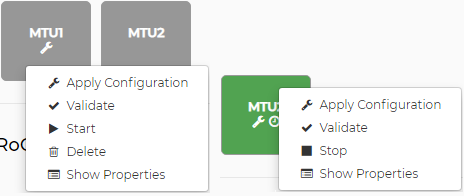
Available Service Element OperationsStatus
Operations Available
Operations Description
Initializing
None
N/A
Idle
Apply Configuration
Configures the service.
Once the configuration is applied, the service status will automatically change to "Monitoring", and start periodic validation.
Only once the configuration is applied, the "Validate" and operation will become available.
Apply Changes
Available if the service has been edited since applying the configuration. Applies only the configuration changes.
Clean-up
Cleans-up the configuration done by the service. Once the configuration is cleaned, the service status will automatically change to "Idle", and stop periodic validation. Previous configuration and validation status will be reset.
WarningClean-up is currently supported for RoCE and MLAG service types on Onyx and Cumulus switches.
WarningMLAG clean-up is only supported for MLAG services created in NEO 2.6 and above.
WarningAfter MLAG clean-up is performed, MPO VLAN, IP routing, IP DHCP relay instance, LACP, and protocol MAGP configuration will remain on Onyx switches. For Cumulus switches, only the MPO's VLAN configuration remains.
Validate
Validates the configuration of the service.
Start
Starts a periodic validation of the service (default interval is 30 minutes). This will change the status to “Monitoring”.
Delete
Deletes the service.
Show Properties/ Edit Service
Shows the information filled when the service was created. Some service types can be edited.
InitializingFailure
Delete
Deletes the service.
Show Properties
Shows the information filled when the service was created.
Monitoring
Stop
Stops a periodic validation of the services. This will change the status to “Idle”.
Show Properties/ Edit Service
Shows the information filled when the service was created. Some service types can be edited.
Device configuration backup: Before configuration changing operations (Apply Configuration, Apply Changes, Clean-up: see table above), a network snapshot will be created for all the devices that are about to be configured. This snapshot can be used to revert to the original device state if the configuration fails, or if it has unwanted implications. If the snapshot creation fails the operation will not run.
Element Icons: Each service element contains the following:
The name of the service
The wrench icon – if the last configuration status of the service was “Unknown”
The clock icon – if the service state is Monitoring
The spinner icon – if the service is going under a validation or configuration process at the moment
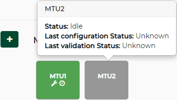
Element Information: When hovering over an element, the following information will be displayed:
The service’s “state”
The service’s “last configuration status”
The service’s “last validation status”
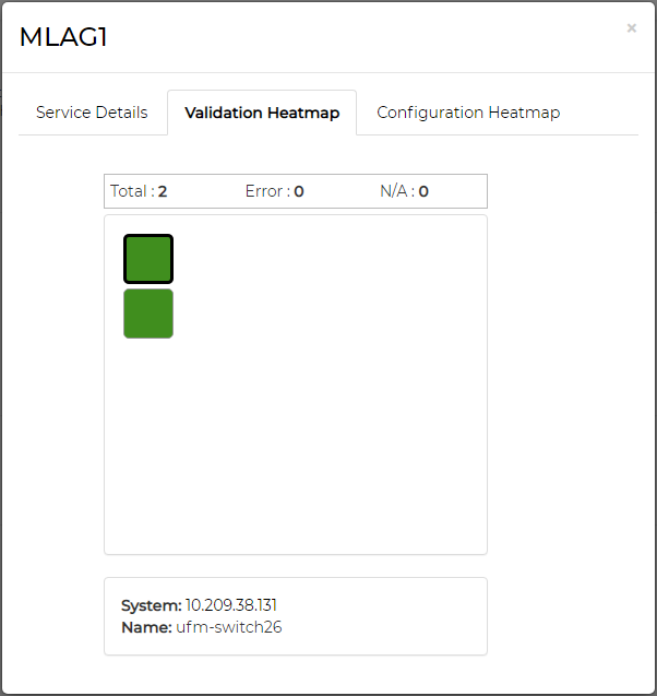
Service Details Modal: When clicking a service element, a modal with more details about the service will appear. The modal consists of three tabs:
“Service Details” tab – lists the service type, the time it was created, the time it was last updated, the last validation status and time, and the last configuration status and time.
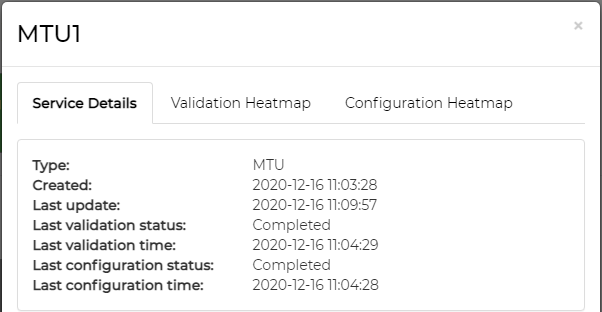
If the service initialization fails, an error message will be added to the bottom of Service Details list.
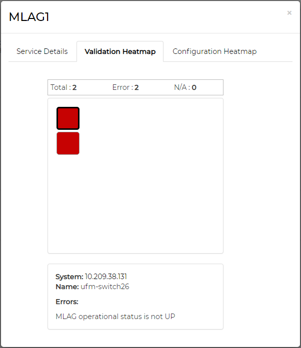
“Validation Heatmap” tab – provides a validation heatmap of the service devices, colored according to their validation job status (Completed – Green, Completed with Errors – Red, Unknown – Grey). When clicked on a device, more details about its IP and name (and the relevant errors if there are any) will be displayed.
“Configuration Heatmap” tab – provides a configuration heatmap of the service devices, colored according to their configuration job status (Completed – Green, Completed with Errors – Red, Unknown – Grey). When clicked on a device, more details about its IP and name (and the relevant errors if there are any) will be displayed.