
AutoMagicCalib#
Overview#
Auto Magic Calib Microservice enables automatic calibration of multi-camera and single-camera systems through a simple, web-based, step-by-step workflow.
It is powered by AutoMagicCalib (AMC), which estimates camera intrinsics and extrinsics to generate accurate projection matrices and lens distortion parameters for 3D and multi-view applications.
Unlike checkerboard-based methods, AMC uses naturally moving objects in the scene. With NVIDIA DeepStream detection and tracking, it follows objects (e.g., people) and derives camera parameters from normal operational footage—no setup, no downtime, and supports calibration from archived videos.
The service supports both a geometry-based approach (AMC) using object trajectories and geometric relationships, and a model-based approach (VGGT) that leverages learned models for higher accuracy and robustness. VGGT is optional, available for multi-camera projects only (two or more cameras), and requires the VGGT model on the backend.
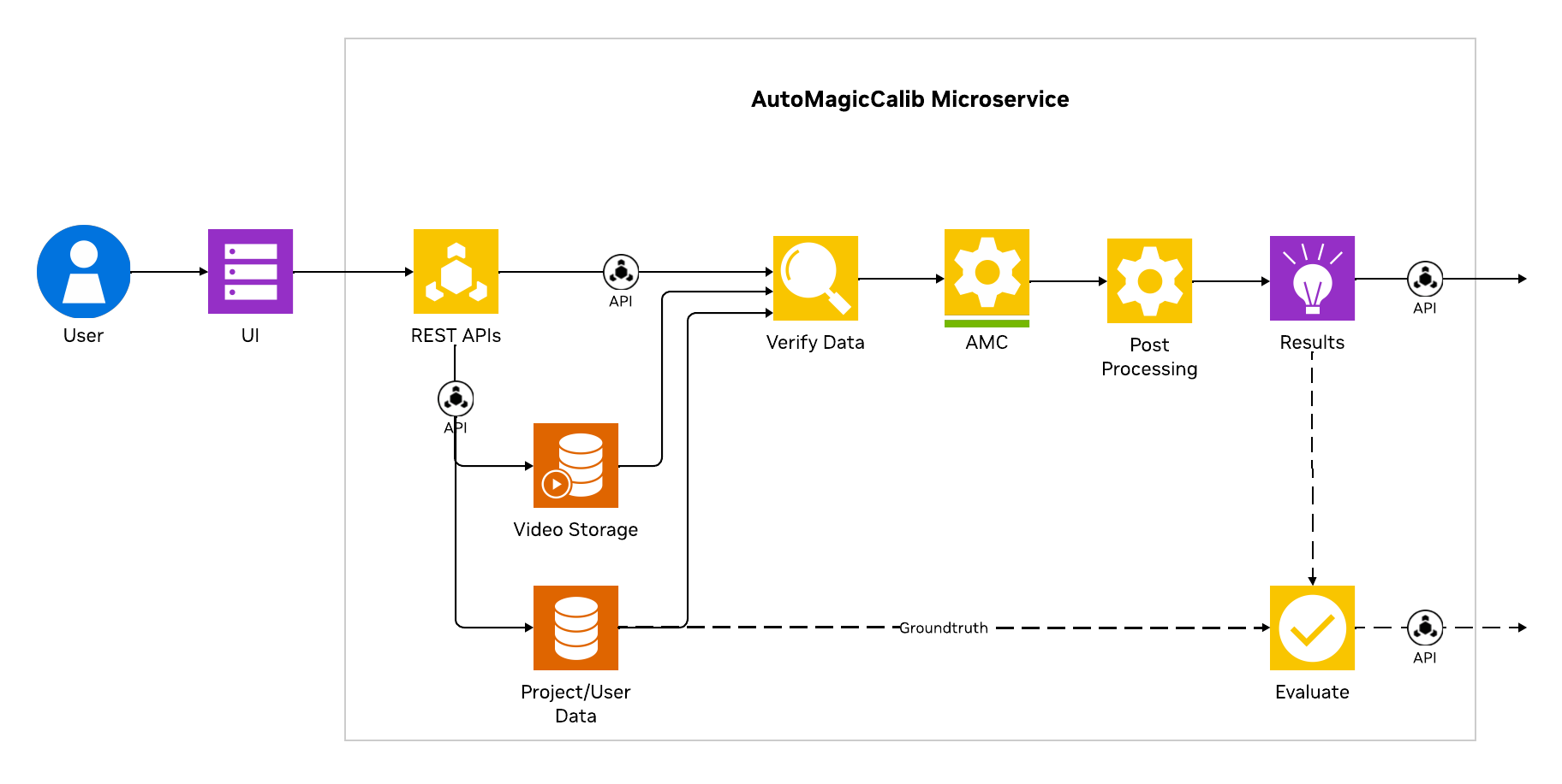
Auto Magic Calib microservice architecture#
Note
This document describes the Auto Magic Calib Microservice and UI. For standalone usage, detailed options, and advanced usage, see the AutoMagicCalib GitHub Repository.
Key Features#
Guided Workflow: 6-step process with progress tracking and real-time validation at each step
Project Management: Create and manage multiple projects; track states (INIT, READY, RUNNING, COMPLETED, ERROR); refresh, delete individual projects, or Delete all; data persistence
Flexible Video Input: Upload MP4 files or time-synchronized RTSP streams (when VIOS is configured on the server); one camera for single-camera calibration, two or more for multi-camera
Interactive Tools: Per-camera and global (layout-map) ROI drawing, tripwire configuration, manual alignment (camera-to-world), real-time preview; Export image-mode JSON for pixel-coordinate ROIs/tripwires without running calibration
Dual Calibration Methods: AMC (primary) and optional VGGT (Vision-Geometry Graph Transformer); VGGT can complete successfully even if AMC failed after rectification (e.g., during multi-view tracklet matching)
Export Options: Full export dialog (AMC or VGGT when both available), MV3DT-compatible ZIP (AMC and VGGT), per-camera parameter export, ROI/tripwire world-coordinate verification on BEV
The calibration process follows: Project Setup → Video Configuration → Parameters → Manual Alignment → Execute → Results. Each step validates inputs before allowing progression to the next.
System Requirements#
x86_64 system
OS Ubuntu 24.04
NVIDIA GPU with hardware encoder (NVENC)
NVIDIA driver 590
NVIDIA container toolkit
Docker (configured to run without sudo privilege)
Required for calibration
Input videos or RTSP streams that meet Input Video Requirements below
Layout/map image (PNG format)
Tracklet-Based Calibration: Input Video Requirements#
AutoMagicCalib (AMC) estimates camera parameters by detecting and tracking people in your footage, then matching those trajectories (tracklets) across camera views. Calibration quality depends heavily on input video content. Review these requirements before you deploy the service or record footage.
Note: These requirements apply to the tracklet-based AMC pipeline (the default calibration path). This is not applicable to the optional VGGT model-based calibration path.
Video content (required for AMC)
Moving people: People must be clearly visible and moving throughout the clip. AMC relies on PeopleNet detection and 3D tracking of people in the scene.
Scene coverage: Trajectories should span as much of each camera’s field of view as possible. More unique walkers and broader coverage produce more usable tracklets.
Recommended headcount: Plan for many moving people in the scene. As a practical guideline, aim for at least 10 unique individuals walking through the monitored area during the recording window (more is better for multi-camera overlap).
Video duration
Recommended: five minutes or longer per camera. There is no strict minimum, but given the size of the space to calibrate and normal walking speed, longer clips let the tracker build stable trajectories across the field of view; short clips often fail during multi-view tracklet matching.
Resolution and format
Resolution: 1920 × 1080
Format (file upload): MP4
Multi-camera specifics
Camera count: Two or more time-synchronized videos or RTSP streams (one stream for single-camera calibration).
Time synchronization: All cameras must cover the same time window. Use clips recorded in sync or post-processed to be in sync.
FOV order: List cameras in order of overlapping field of view (
cam_00overlapscam_01,cam_01overlapscam_02, and so on).FOV overlap: For the best calibration quality, more overlap between consecutive camera pairs is better. Aim for at least 30% FOV overlap; insufficient overlap reduces matched tracklets and often causes multi-view calibration to fail.
Tracklet thresholds (why the above matters)
AMC filters and matches tracklets before multi-view calibration. Default pipeline settings include:
Minimum tracklet length: 90 frames (approximately three seconds at 30 fps)—short or jittery tracks are discarded.
Minimum matched tracklets (multi-camera): six cross-camera tracklet correspondences per camera pair (three in robust two-view fallback).
If your videos lack enough moving people or are too short, calibration may fail at detection, tracking, or tracklet matching. You may need to adjust the configuration parameters through the UI or capture better videos. See Custom Dataset below for capture best practices.
Lens Distortion Output (distortion.yaml)#
AMC can accept videos that contain lens distortion. When rectification is enabled (distortion model set to something other than pinhole in the rectification settings), the pipeline:
Estimates per-camera distortion parameters (primarily k1)
Rectifies video frames internally so that subsequent calibration (tracking, tracklet matching, bundle adjustment) runs on undistorted imagery
Writes estimated parameters to disk for downstream use
Important for downstream applications
Rectified videos (rectified.mp4) are produced under each camera’s single-view output folder on the server, but they are not automatically substituted for your original camera feeds in downstream applications. Exported calibration JSON and MV3DT ZIP files describe cameras in the rectified (undistorted) image space.
To stay consistent with AMC calibration results, downstream applications must either:
Apply the saved
distortion.yamlparameters to undistort live or recorded frames before using AMC projection matrices, orManually replace input videos with the per-camera
rectified.mp4files from the calibration output (not wired automatically by the microservice)
Output location
Per camera (example paths on the calibration server):
<project_output>/single_view_results/cam_00/distortion.yaml
<project_output>/single_view_results/cam_00/geocalib_distortion.yaml   # when GeoCalib estimates distortion
<project_output>/single_view_results/cam_00/rectified.mp4
``distortion.yaml`` format
This is the parameter file AMC rectification writes for application use. It contains the distortion coefficient in AMC/OpenCV pixel-centered convention (focal length treated as 1, origin at image center):
k1: -1.2345678e-06
``geocalib_distortion.yaml`` format (when distortion estimation runs)
GeoCalib writes a richer record that includes the distortion model name and both coordinate conventions:
model: simple_radial        # or radial, simple_divisional (must match rectification config)
k1: -1.2345678e-06          # AMC/OpenCV convention: radial factor = 1 + k1 * r_pixel^2
k1_geocalib: -4.5678901e-03 # GeoCalib internal normalized coordinates
focal_length: 1269.0        # focal length used for k1 conversion
source: geocalib
k2: ...                     # present only when model is radial
Distortion model
AMC rectification uses a Brown–Conrady radial model (inverse mapping for undistortion). For the default simple_radial model, only k1 is non-zero:
Undistorted normalized radius:
r_u = r_d * (1 + k1 * r_d^2 + k2 * r_d^4 + k3 * r_d^6)(iterative inverse solve)Pixel coordinates use the image center as the principal point;
k1indistortion.yamlis already scaled to full-resolution pixel units
Supported model names (set in rectification config, must match between GeoCalib and rectification):
pinhole— no distortion; rectification skippedsimple_radial— single k1 term (most common)radial— k1 and k2 termssimple_divisional— division model variant
Applying distortion correction downstream
Use k1 from distortion.yaml with OpenCV’s undistortion APIs. Example (Python, per frame):
import cv2
import numpy as np
import yaml

with open("distortion.yaml") as f:
    k1 = float(yaml.safe_load(f)["k1"])

h, w = frame.shape[:2]
camera_matrix = np.array([[1, 0, w / 2], [0, 1, h / 2], [0, 0, 1]], dtype=np.float64)
dist_coeffs = np.array([k1, 0, 0, 0], dtype=np.float64)
rectified = cv2.undistort(frame, camera_matrix, dist_coeffs)
Ensure the same image resolution (1920 × 1080) and that you undistort before projecting detections with AMC camera matrices. If rectification was disabled (pinhole / general.skip: true), no distortion.yaml is needed and raw video matches calibration space.
See also Custom Dataset (lens distortion guidance) and the AutoMagicCalib rectification_config.yaml in the source repository for tuning search ranges and model selection.
Optional
Ground truth data (ZIP file) for calibration evaluation
Pre-existing alignment data (JSON file)
Focal length values for cameras
Config parameters for your dataset
VIOS server and
VIOS_BASE_URLconfiguration for RTSP URLs input
Quick Start#
Deploy the UI and backend microservice using Docker Compose.
NGC Setup#
This step is needed to pull AutoMagicCalib docker image.
Visit NGC sign in page, enter your email address and click Next, or Create an Account
Choose your Organization/Team
Generate an API key following the instructions
Log in to the NGC docker registry:
docker login nvcr.io
Username: "$oauthtoken"
Password: "YOUR_NGC_API_KEY"
Project Setup#
Clone the repo to your local directory.
git clone https://github.com/NVIDIA/DeepStream.git
cd DeepStream/tools/auto-magic-calib
Optional VIOS Setup for RTSP Capture#
RTSP support requires VIOS_BASE_URL. If a VIOS server is already reachable from the AMC host, verify it before setting VIOS_BASE_URL in compose/.env. Without VIOS, the rest of the calibration workflow can run, but RTSP support remains disabled.
If VIOS is not deployed yet, use the VIOS deployment assets from the VSS repository. Follow 1click_README.md in that directory. A typical development deployment command is:
sudo python3 oneclick_dc_deployment_for_dev.py --auto
Verify VIOS before enabling it:
curl http://<vios-host>:30888/vst/api/v1/sensor/list
Configure Environment Variables#
Edit the compose/.env file to set the required environment variables.
Variable |
Required |
Default |
Description |
|---|---|---|---|
|
Yes |
— |
IP address of the host machine |
|
No |
|
Port for the microservice API |
|
No |
|
Port for the web UI |
|
No |
|
Path to the projects directory (can be modified to absolute path to your projects directory) |
|
No |
|
Path to the models directory (can be modified to absolute path to your models directory) |
|
No |
— |
VIOS server URL for RTSP capture APIs |
AUTO_MAGIC_CALIB_MS_PORT=8000
AUTO_MAGIC_CALIB_UI_PORT=5000
PROJECT_DIR=../../projects
MODEL_DIR=../../models
HOST_IP="<your_host_ip>"
# VIOS_BASE_URL=http://<VIOS_HOST_IP>:30888  # Uncomment and update this to support RTSP streams
HOST_IP must not be empty. If it is empty, the UI API URL renders as http://:<port>/v1.
Leave VIOS_BASE_URL unset to keep RTSP capture disabled.
Set Directory Permissions#
The projects and models directories must be owned by UID/GID 1000 for the containers to read/write properly.
sudo chown 1000:1000 -R projects
sudo chown 1000:1000 -R models
Launch Services#
Start all services using Docker Compose. Docker images will be pulled automatically on the first run.
cd compose
docker compose up -d
The microservice will be available at http://<HOST_IP>:<AUTO_MAGIC_CALIB_MS_PORT> (default port 8000) and the UI at http://<HOST_IP>:<AUTO_MAGIC_CALIB_UI_PORT> (default port 5000).
Note
To stop: docker compose down.
For VGGT, download the model from HuggingFace (e.g. VGGT-1B-Commercial) and place vggt_1B_commercial.pt in the models directory.
Workflow Steps#
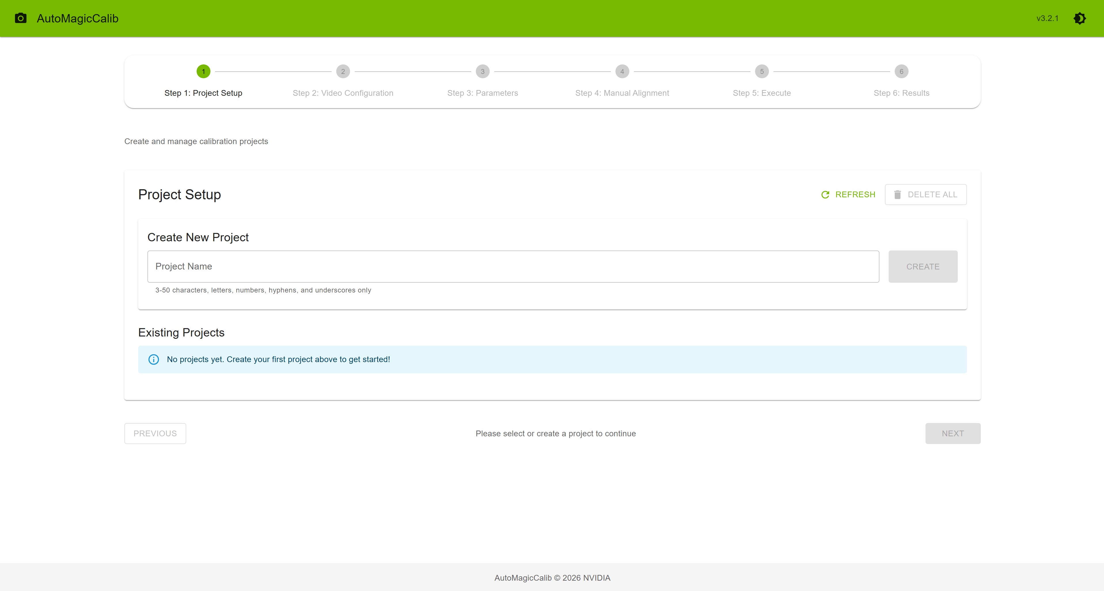
Step 1: Project Setup — Create a project (name 3–50 characters), click “Create”, then “Select”. Project cards show state (INIT, READY, RUNNING, COMPLETED, ERROR), video count, and file status (GT, Layout, Alignment). Refresh, delete individual projects, or use Delete all (projects with calibration running or RTSP capture in progress are skipped).
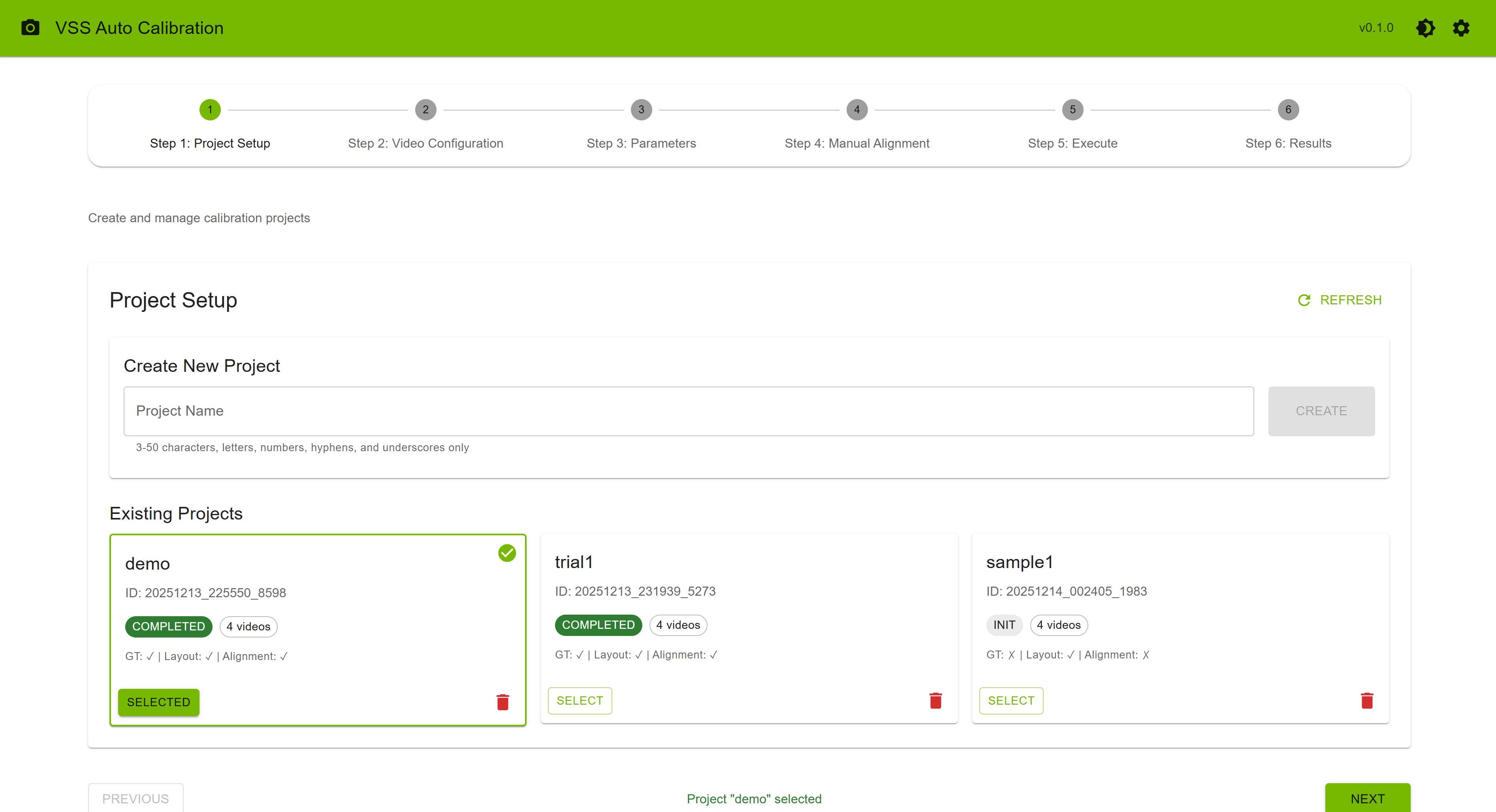
Project Setup Step#
Step 2: Video Configuration — Provide camera inputs using either file upload or RTSP URLs (VIOS; shown only when configured on the server). Minimum one video (MP4, 1920×1080 recommended); two or more for multi-camera. Order videos by overlapping FOV (cam_00, cam_01, …). The UI does not allow mixing an active file-upload queue with RTSP—remove file-uploaded clips before switching to RTSP, and vice versa.
Option A: Upload video files — Select, reorder by drag-and-drop, then upload.
Option B: RTSP URLs (VIOS is Configured) — Set duration (minimum 60 seconds). Enter all RTSP URLs under Streams before a single Start capture (one session for every camera). Do not add streams later or run staggered captures—time synchronization requires one combined capture. Optionally Stop early after 60 seconds of recording; when COMPLETED or CANCELLED, click Ingest to project. For VIOS pre-registered streams, use the source URL (e.g., NVStreamer URL), not the VIOS-proxied URL.
Also upload a required layout image (PNG) and optional ground truth (ZIP) or alignment (JSON).
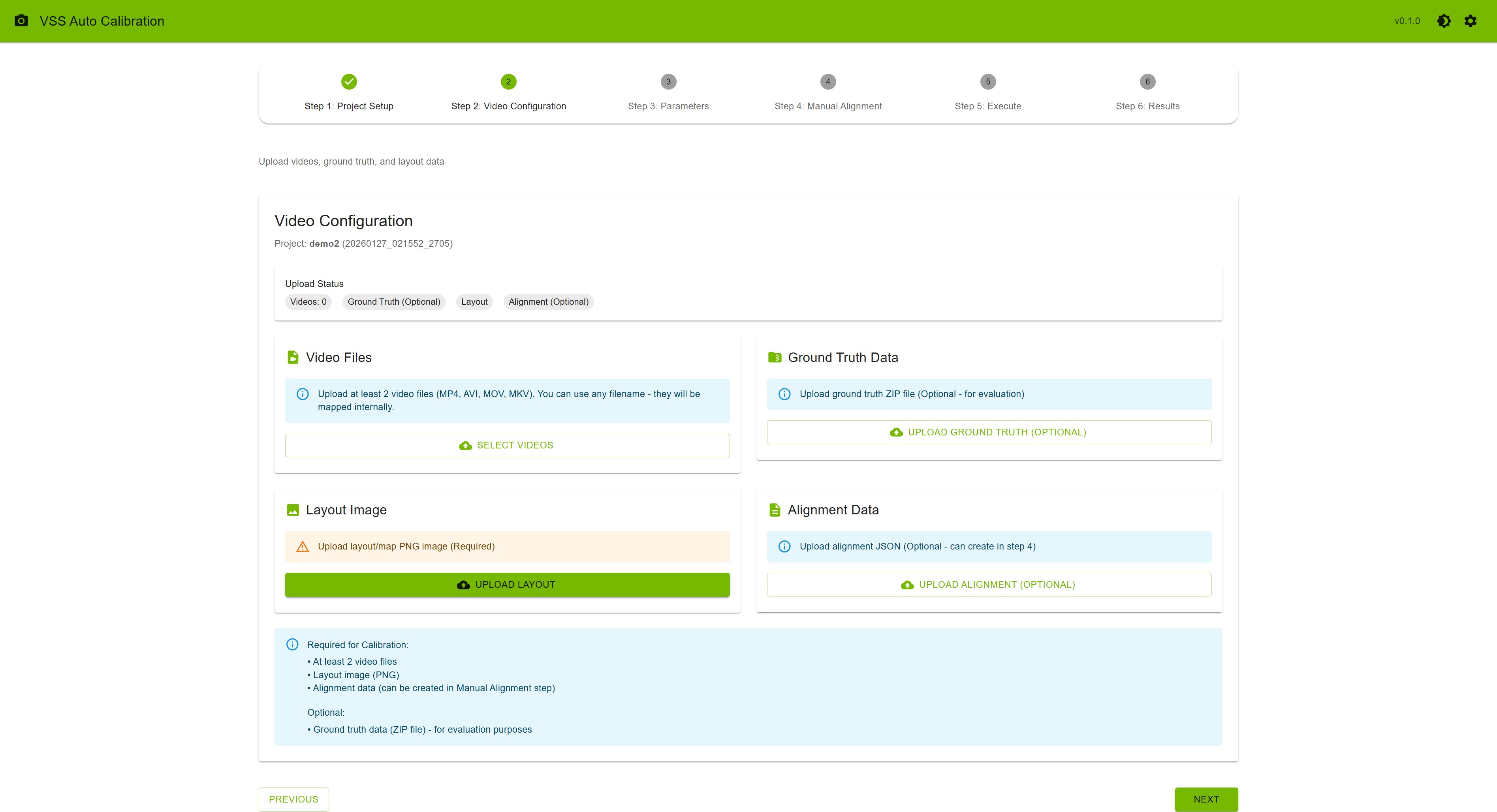
Video Configuration Step#
Step 3: Parameters — Under Annotation target, choose Camera (per-stream ROIs/tripwires on video frames) or Global ROIs / tripwires (draw on the layout map; requires layout from Step 2). Use Draw ROI (polygon, min 3 points; press F or right-click to finish), Draw Tripwire, and Tripwire Direction; Show/Hide and Reset per target. Annotations auto-save.
Optional: Export image-mode JSON (pixel coordinates, calibrationType: image, no calibration required); focal lengths (comma-separated, one per camera); settings icon on this step only—upload config, adjust manually, download, Reset to Defaults, Save Settings (do not change settings while AMC is running).
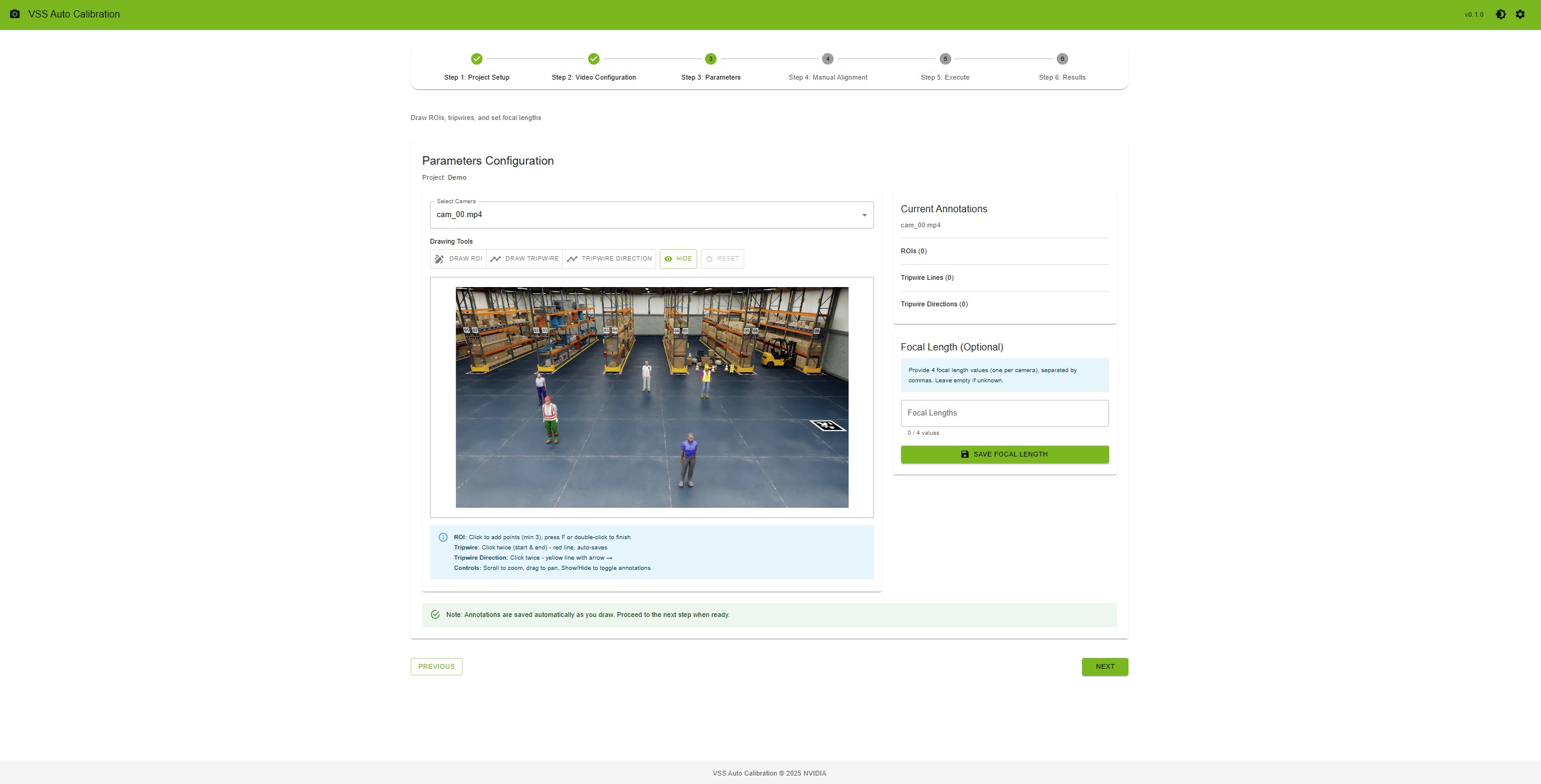
Parameters Step#
Step 4: Manual Alignment — Upload alignment_data.json (Option A) or open the alignment tool (Option B).
Multi-camera (2+ videos): Click the same physical point on Camera 0, Camera 1, and the layout map for each of at least 4 point sets (3 clicks per set); then “Save Alignment”.
Single-camera (1 video): Click the same physical point on the camera and layout map for each of at least 4 point sets (2 clicks per set); then “Save Alignment”.
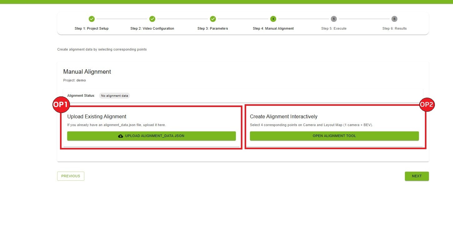
Manual Alignment Step#
If you want to create the alignment data interactively, you can use the alignment tool.
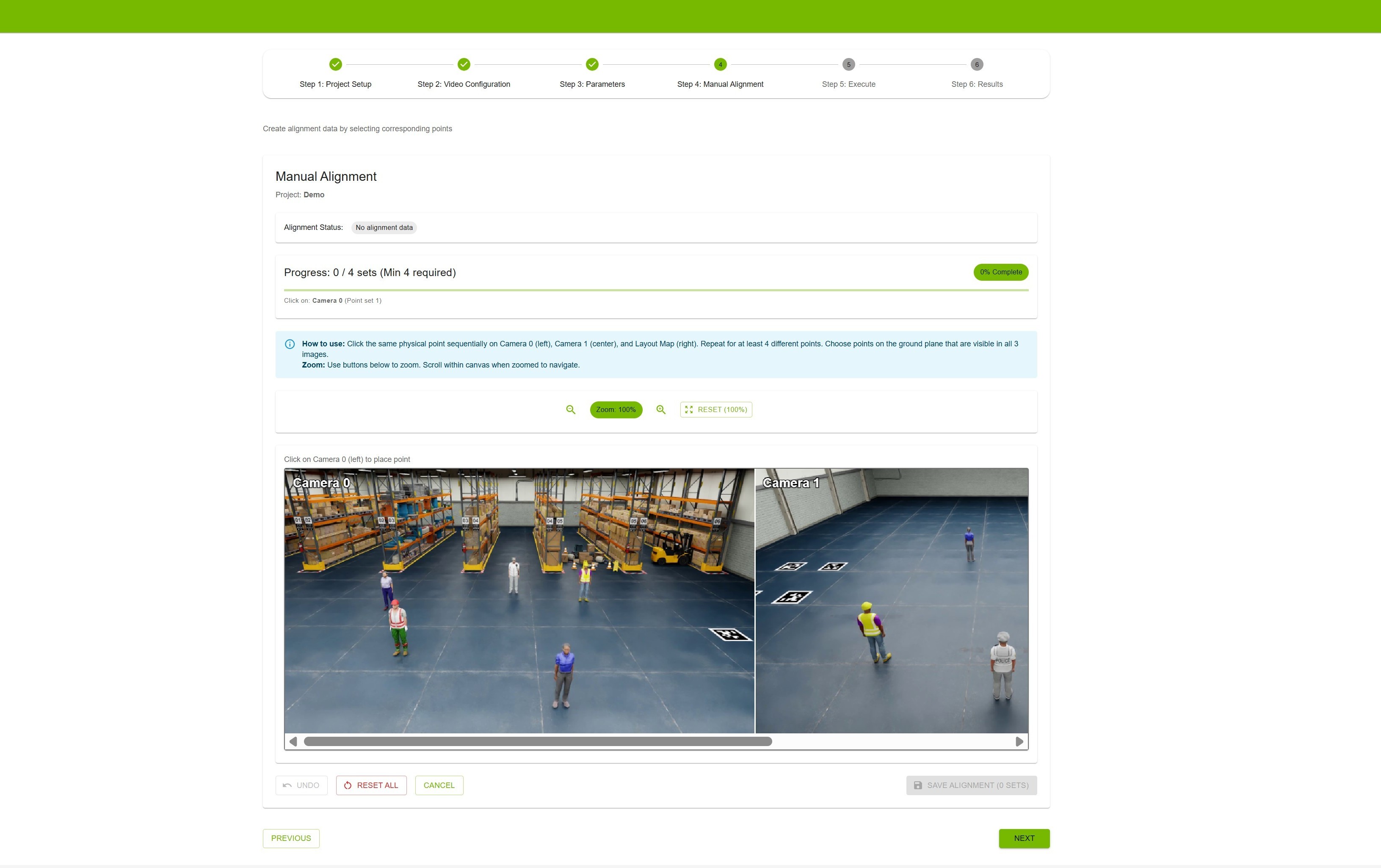
Manual Alignment Tool#
Step 5: Execute — Ensure requirements are met (videos, layout, alignment with 4+ point sets), click “Verify Project”, then “Start Calibration”. Monitor AMC progress (status updates every ~3 seconds; live logs). On failure, use “Relaunch Calibration” or “Reset Project”.
VGGT (optional, multi-camera only): After AMC has produced on-disk outputs (typically after rectification), Run VGGT Calibration when VGGT state is READY—AMC does not need to show COMPLETED. A successful VGGT run sets project state to COMPLETED even if AMC failed (e.g., at tracklet matching). VGGT is not offered for single-camera projects.
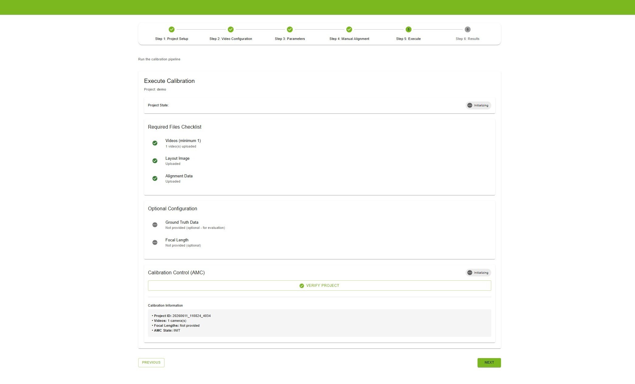
Execute Calibration#
Step 6: Results — Available when AMC or VGGT completed successfully. View overlay image (AMC/VGGT tabs), evaluation metrics (L2 distance if ground truth uploaded), and per-camera parameters (YAML; AMC/VGGT tabs).
Export via Full Export (dialog to choose AMC or VGGT when both exist; optional metadata and JSON editor), MV3DT ZIP AMC, or MV3DT ZIP VGGT (when available). Use Delete Results to re-run calibration.
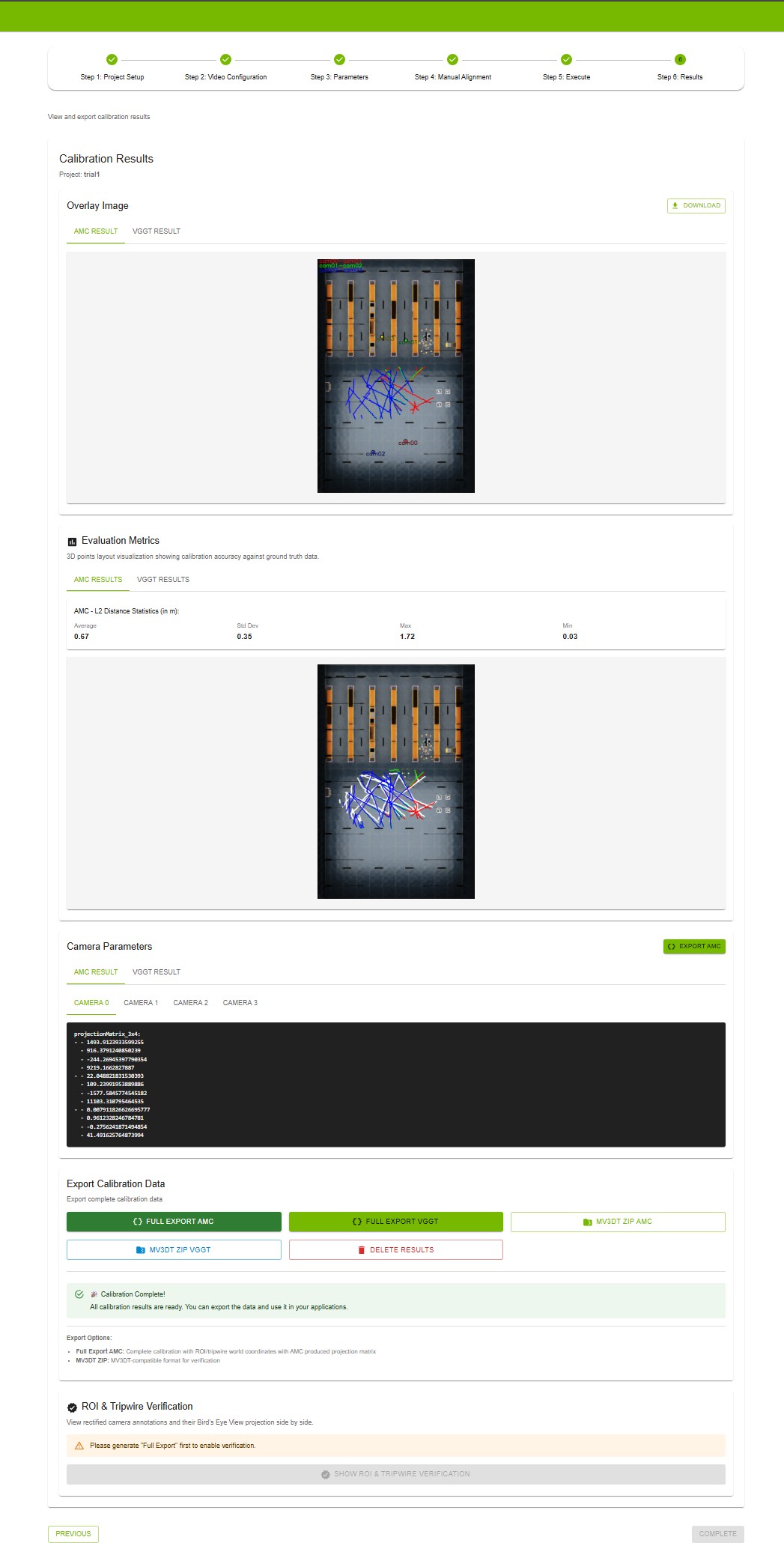
Results Step#
Click Show ROI & Tripwire Verification
Choose Camera or Global ROIs / tripwires in the annotation target toggle
Camera target: pick a stream from Select Camera; review the left rectified frame and the right world map; use AMC / VGGT tabs on the world map as needed
Global target: left panel shows global shapes on layout.png (pixel coordinates); right panel shows their world-map projection in purple
Under the camera view, use checkboxes labeled Global ROI: / Global tripwire: to include or exclude that camera in each ROIs/Tripwires
sensorslist (only global items projected to that camera are listed)Use world-map zoom controls for detail; click Close when finished

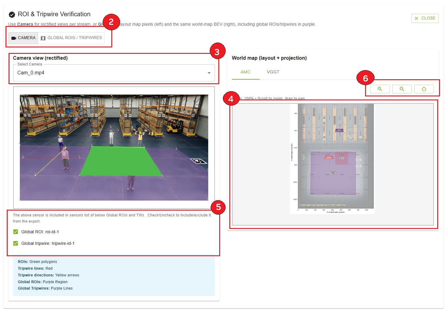
Custom Dataset#
Prepare:
Input videos — One or more camera video files (or time-synchronized RTSP URLs); upload/capture order defines camera pairing and FOV overlap chain; consecutive cameras should have overlapping FOV for multi-camera setups.
Floor map — Layout/map image of the surveillance area (PNG).
Ground truth (optional) — For evaluation, a ZIP containing
calibration.jsonandground_truth.json.
calibration.json — Sensors array; each has id, intrinsicMatrix (3x3), extrinsicMatrix (3x4), cameraMatrix (3x4), attributes (e.g. frameWidth, frameHeight). Matrices follow OpenCV-style definitions.
ground_truth.json — Frame index as key; each value is an array of objects with object id, object type, object name, 3d location [x,y,z], and 2d bounding box visible (camera id → [x_min, y_min, x_max, y_max]).
Guidelines for Input Videos to Achieve Optimal Calibration Results#
To ensure the most accurate camera calibration, careful consideration should be given to how the input videos are captured. The following points detail how to maximize the quality of the calibration outcome.
1. Minimizing Lens Distortion
The current calibration methodology performs best when input videos are “linear,” meaning they exhibit no lens distortion. While the tool can handle minor distortion, optimal results are achieved when lens distortion is zero.
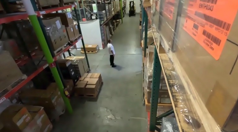
Example of linear video with minimal lens distortion#
2. Maximizing Camera Overlap
Accurate calibration requires a significant degree of overlap between the fields of view of the different cameras. It is essential to maximize the overlap between cameras as much as possible.
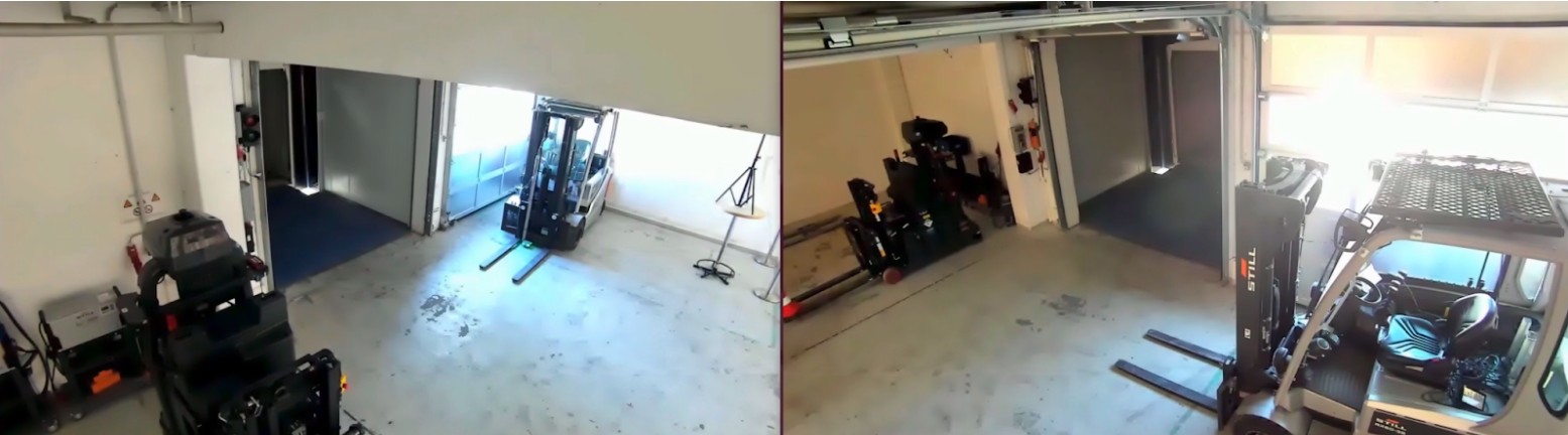
Example of strong overlap between camera fields of view#
3. Leveraging Unique Scene Features
The presence of diverse and unique objects in the input videos contributes significantly to calibration accuracy. The automatic calibration tool specifically utilizes people moving within the field of view, so videos with many moving people are ideal. The trajectories of these moving subjects should cover the Field of View (FOV) as broadly as possible.
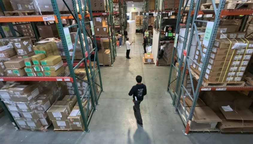
Diverse, unique objects and moving people improve calibration accuracy#
Additionally, large, unique objects can enhance accuracy. For instance, in a setting like a warehouse with multiple cameras, views can become challenging due to repetitive elements (e.g., similar racks). In such environments, large, distinct objects, such as forklifts, are beneficial for better calibration accuracy.
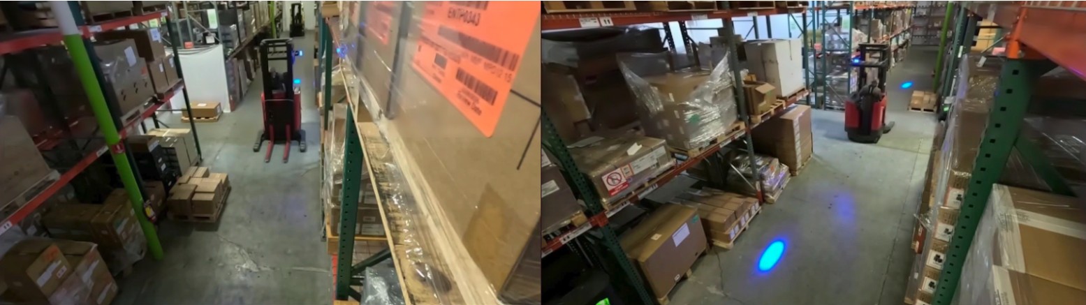
Large distinct objects (e.g., forklifts) in warehouse views aid calibration#
Calibration Output#
After calibration, the UI provides overlay images (AMC and/or VGGT tabs), evaluation metrics (e.g. L2 distance average, std dev, min/max when ground truth is provided), and per-camera parameters (projection matrix, intrinsics/extrinsics in YAML).
With ground truth: Compare L2 distance statistics and overlay trajectories (colored reconstructed paths vs. white ground truth lines) between AMC and VGGT to select the better result.
Without ground truth: Compare overlay images qualitatively—camera positions, object trajectories, and FOV boundaries against the floor map.
Export options include:
Full Export — Complete calibration JSON with ROI/tripwire world coordinates; choose AMC or VGGT in the dialog when both completed (
{project_name}_exported.jsonor{project_name}_exported_vggt.json)Export image-mode JSON (Parameters step) — ROIs/tripwires in pixel coordinates without running bundle adjustment
MV3DT ZIP AMC / MV3DT ZIP VGGT — MV3DT-compatible archives for verification
Integration with MV3DT#
Export calibration in MV3DT-compatible form from the Results step: use MV3DT ZIP AMC or MV3DT ZIP VGGT. The generated ZIP can be used with Multi-View 3D Tracking (MV3DT) verification tools.
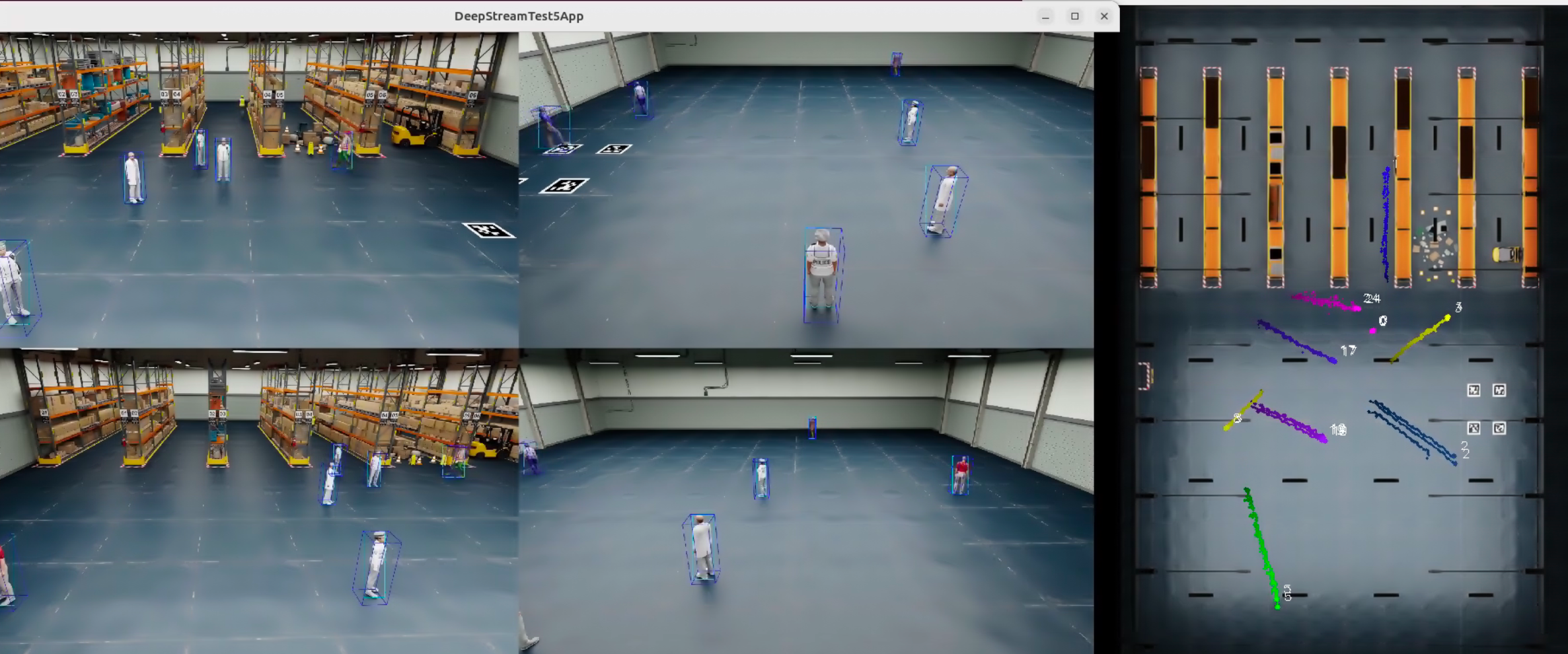
MV3DT real-time multi-view tracking with AMC-generated calibration parameters#
Troubleshooting#
Cannot access UI — Confirm backend and UI are running (e.g. docker ps). Check URL/port, firewall, and connectivity (e.g. ping, telnet <ip> <port>).
Port already in use — Change AUTO_MAGIC_CALIB_MS_PORT and AUTO_MAGIC_CALIB_UI_PORT in compose/.env and restart; or stop the process using the port (e.g. sudo lsof -i :5000).
API_URL_NOT_PROVIDED — Set HOST_IP in compose/.env and restart: docker compose down then docker compose up.
Verification fails — Ensure videos (min 1), layout, and alignment (4+ point sets). Check alignment JSON and video integrity; re-upload if needed.
Calibration fails or takes too long — Check input files and alignment (ground plane, visible in all views/cameras). Typical AMC run 5–15 minutes; VGGT typically 2–3 minutes. If AMC fails after rectification, try Run VGGT Calibration when VGGT state is READY. Reset project and retry if needed.
RTSP URLs as Input issues — Ensure VIOS is configured; use source URLs (not VIOS-proxied) for pre-registered streams; configure all streams before one Start capture; minimum 60 s duration; remove file-uploaded clips before RTSP and vice versa.
VGGT not available — Install VGGT model on backend; VGGT requires multi-camera (2+ videos). Single-camera projects do not support VGGT.
Export or ROI verification issues — Ensure at least one calibration path (AMC or VGGT) completed. Use Show ROI & Tripwire Verification after calibration; for full world-coordinate export, use Full Export and choose AMC or VGGT as needed.
Additional Resources#
GitHub Repository: AutoMagicCalib for standalone AMC and sample data.
VGGT model: Optional; download from HuggingFace (e.g. VGGT-1B-Commercial) and place in the models directory for VGGT refinement.