DOCA HBN Service
NVIDIA DOCA HBN Service Guide
This document provides instructions on how to use the DOCA HBN Service container on top of NVIDIA® BlueField® DPU.
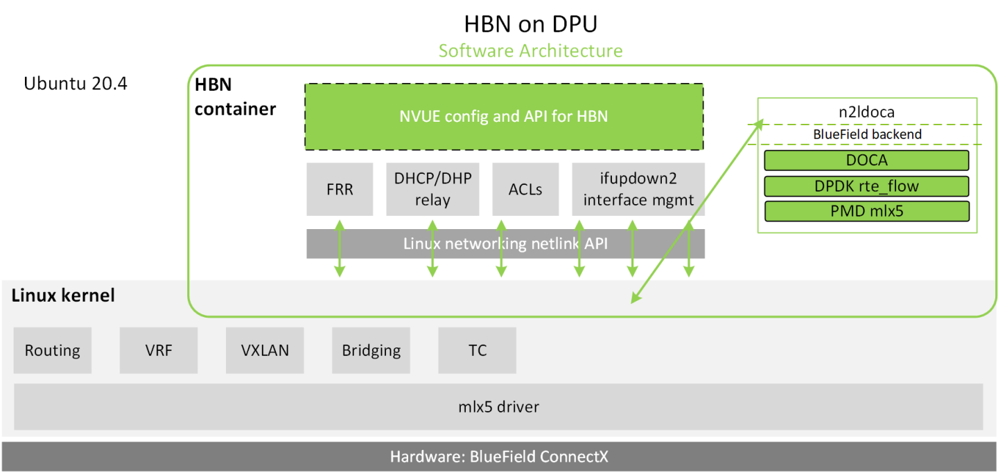
Host-based networking (HBN) is a DOCA service that enables the network architect to design a network purely on L3 protocols, enabling routing to run on the server-side of the network by using the DPU as a BGP router. The EVPN extension of BGP, supported by HBN, extends the L3 underlay network to multi-tenant environments with overlay L2 and L3 isolated networks.
The HBN solution packages a set of network functions inside a container which, itself, is packaged as a service pod to be run on the DPU. At the core of HBN is the Linux networking DPU acceleration driver. Netlink to DOCA daemon, or nl2docad, implements the DPU acceleration driver. nl2docad seamlessly accelerates Linux networking using DPU hardware programming APIs.
The driver mirrors the Linux kernel routing and bridging tables into the DPU hardware by discovering the configured Linux networking objects using the Linux Netlink API. Dynamic network flows, as learned by the Linux kernel networking stack, are also programmed by the driver into DPU hardware by listening to Linux kernel networking events.
The following diagram captures an overview of HBN and the interactions between various components of HBN.
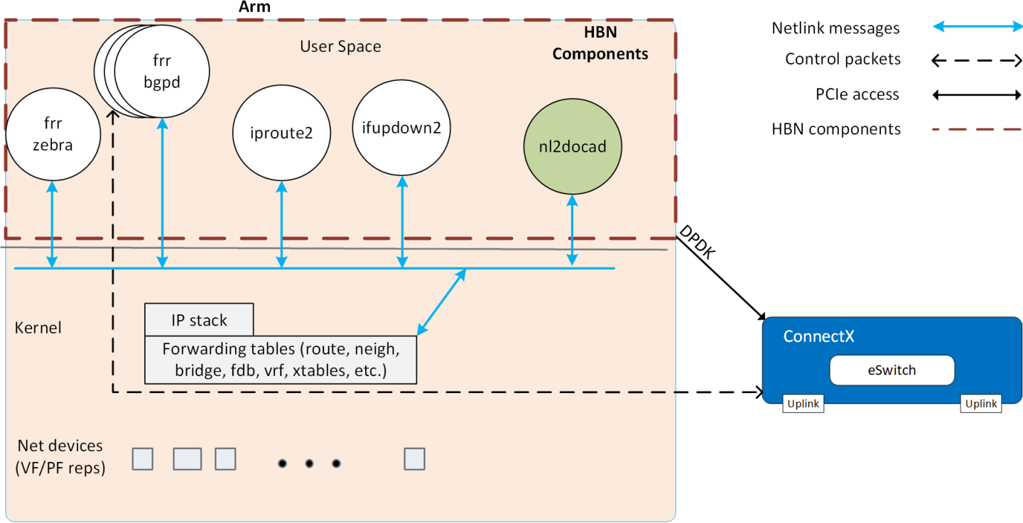
- ifupdown2 is the interface manager which pushes all the interface related states to kernel
- The routing stack is implemented in FRR and pushes all the control states (EVPN MACs and routes) to kernel via netlink
- Kernel maintains the whole network state and relays the information using netlink. The kernel is also involved in the punt path and handling traffic that does not match any rules in the eSwitch.
- nl2docad listens for the network state via netlink and invokes the DOCA interface to accelerate the flows in the DPU HW tables. nl2docad also offloads these flows to eSwitch.
The Arm Linux system on the DPU comes with a set of four interfaces or netdevices:
- Two uplinks (
p0,p1) - Two port representors (
pf0hpf,pf1hpf)
As shown in the following image, the port representatives are each linked with the corresponding host representatives on the host server (usually named ens1f0 and ens1f1 depending on udev rules and PCIe slot numbers).
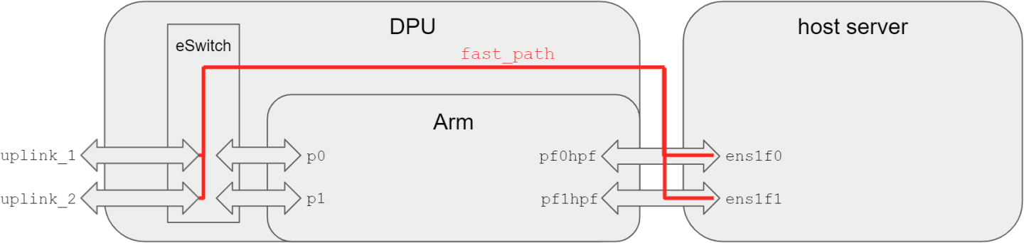
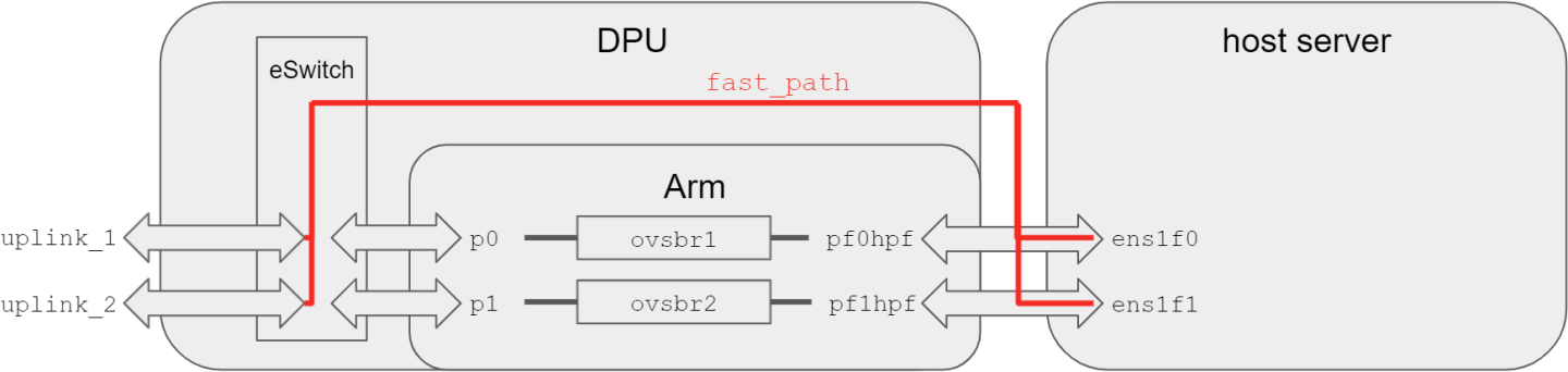
After a fresh DOCA BFB installation, the DPU comes with OVS installed and a default OVS configuration already applied.
As shown in the figure below, the default configuration has two bridges:
ovsbr1(bridgep0andpf0hpf)ovsbr2(bridgep1andpf1hpf)
With this configuration, any packets coming to uplink_1/p0 reaches the host server on ens1f0. Similarly, packets coming to uplink_2 will reach ens1f1. The same is true for the transmit direction.
As seen in the following figure, the default configuration for HBN is different: There is only one bridge, and the bridge is only connected to the port representative pf0hpf. The second port representors pf1hpf is not used.
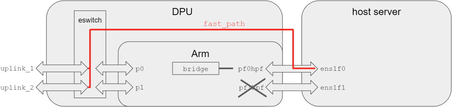
However, on the host server, the host representative ens1f1 is still visible. To hide it from the user, you must run the following command and power cycle (reboot) the server:
mlxconfig -d /dev/mst/mt41686_pciconf0 s HIDE_PORT2_PF=True
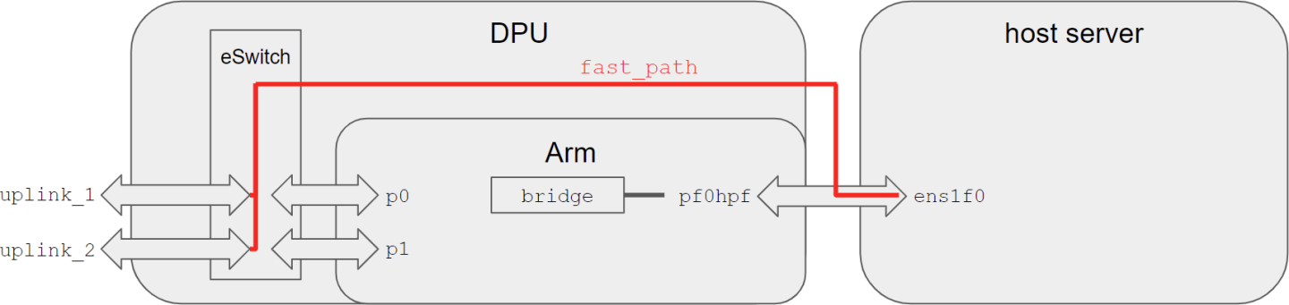
After applying the mlxconfig command (on host server or the DPU) and rebooting the host server, the following diagram represents the default HBN configuration:
The diagram above shows the following:
- Host OS sees the DPU as the default gateway
- Host maintains per-tenant VLAN mapping
- DPU is unaware of the tenants
- DPU has tenant VLAN-VNI mapping
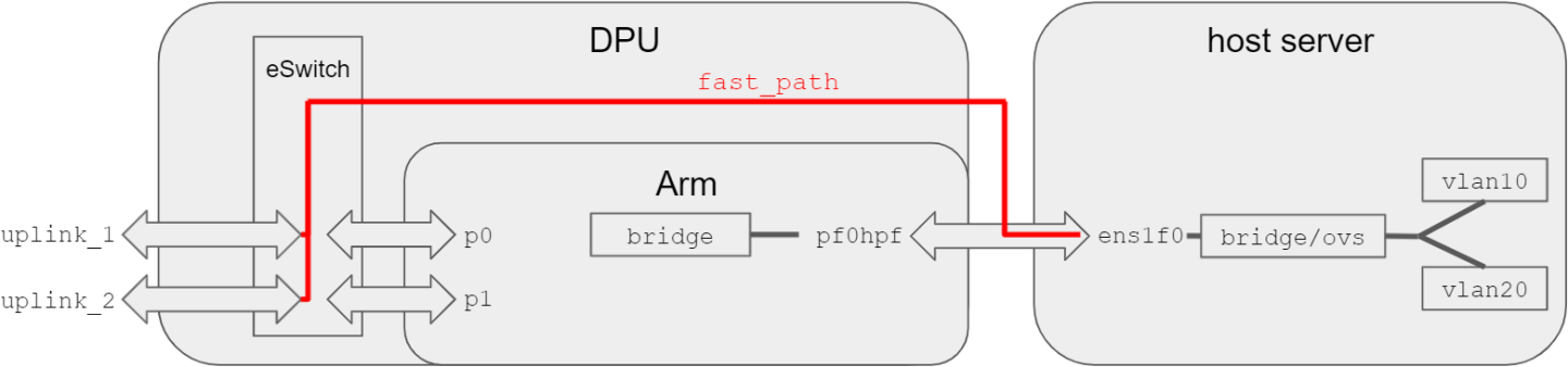
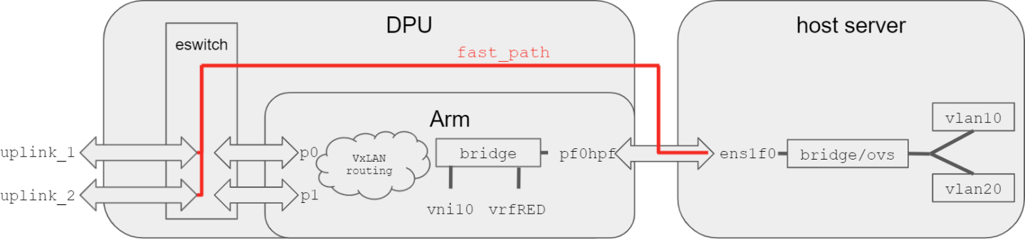
When, for example, a VXLAN configuration is applied to the DPU, p0/p1 reaches the bridge and thus the host server, via routing, as depicted in the following figure.
For information about the deployment of DOCA containers on top of the BlueField DPU, refer to NVIDIA DOCA Container Deployment Guide.
HBN service is available on NGC, NVIDIA's container catalog. Service-specific configuration steps and deployment instructions can be found under the service's container page.
Make sure to follow the instructions in the NGC page to verify that the container is running.
Add network interfaces and FRR configuration files on the DPU to achieve the desired configuration:
/etc/network/interfacesNote:Refer to NVIDIA® Cumulus® Linux documentation for more information.
Note:Virtual functions (VFs) can also be used in /etc/network/interfaces in place of PFs. After creating/removing VFs from the host server, restart the
rc-bf2-localservice using the following command:systemctl restart rc-bf2-local
/etc/frr/frr.confNote:Refer to NVIDIA® Cumulus® Linux documentation for more information.
/etc/frr/daemons
5.1. Traffic Does Not Reach DPU from Host Server
Check that the uplink corresponding to the port representor is connected and in the UP state.
For example, if the p0 uplink is not cabled and is thus in NO-CARRIER, then pf0hpf will not receive any traffic from the host server. In this case, pf1hpf must be used instead for HBN configuration.
5.2. HBN Container Does Not Start
If the container is not starting and is not appearing in crictl ps output, check Kubelet logs with the following:
journalctl _SYSTEMD_UNIT=kubelet.service
If the following message appears in the logs, try rebooting the DPU to free up the huge pages resources:
"Failed to admit pod, unexpected error while attempting to recover from admission failure" pod="default/doca-app-hbn-hbn-01-00" err="preemption: error finding a set of pods to preempt: no set of running pods found to reclaim resources: [(res: hugepages-2Mi, q: 1073741824), ]"
The following subsections contain instructions on different BlueField configuration files as shown in different configuration modes related to the HBN DOCA service.
6.1. Sample EVPN Configuration
6.1.1. ECMP Configuration
ECMP is implemented any time routes have multiple paths over uplinks. For example:
            10.0.1.1 proto bgp metric 20
        nexthop via 169.254.0.1 dev p1 weight 1 onlink <<<<<via uplink p1
        nexthop via 169.254.0.1 dev p0 weight 1 onlink <<<<<via uplink p0
The following is a sample config which has 3 VRFs for EVPN symmetric routing, as well as corresponding L3-VNIs (vx-4001, vx-4002, vx-4003) and L2-VNIs (vx-1000, vx-1002, vx-1004, vx-1006) for EVPN bridging.
6.1.1.1. Sample Interface Configuration
This file is located at /etc/network/interface.
            auto lo
iface lo inet loopback
    address 10.10.10.200/32
    vxlan-local-tunnelip 10.10.10.200

auto vrf1
iface vrf1
  vrf-table auto

auto vrf2
iface vrf2
  vrf-table auto

auto vrf3
iface vrf3
  vrf-table auto

auto p0
iface p0

auto p1
iface p1

auto vx-1000
iface vx-1000
    vxlan-id 1000
    bridge-access 1000
    mtu 9152

auto vx-1002
iface vx-1002
    vxlan-id 1002
    bridge-access 1002
    mtu 9152

auto vx-1004
iface vx-1004
    vxlan-id 1004
    bridge-access 1004
    mtu 9152

auto vx-1006
iface vx-1006
    vxlan-id 1006
    bridge-access 1006
    mtu 9152

auto vx-1008
iface vx-1008
    vxlan-id 1008
    bridge-access 1008
    mtu 9152

auto vx-4001
iface vx-4001
    vxlan-id 4001
    bridge-access 4001
    mtu 9152

auto vx-4002
iface vx-4002
    vxlan-id 4002
    bridge-access 4002
    mtu 9152

auto vx-4003
iface vx-4003
    vxlan-id 4003
    bridge-access 4003
    mtu 9152

auto vlan1000
iface vlan1000
    address 172.16.0.2/24
    address-virtual 00:00:5e:00:01:01 172.16.0.1/24
    vlan-id 1000
    vlan-raw-device bridge
    vrf vrf1

auto vlan1002
iface vlan1002
    address 172.16.2.2/24
    address-virtual 00:00:5e:00:01:01 172.16.2.1/24
    vlan-id 1002
    vlan-raw-device bridge
    vrf vrf1

auto vlan1004
iface vlan1004
    address 172.16.4.2/24
    address-virtual 00:00:5e:00:01:01 172.16.4.1/24
    vlan-id 1004
    vlan-raw-device bridge
    vrf vrf2

auto vlan1006
iface vlan1006
    address 172.16.6.2/24
    address-virtual 00:00:5e:00:01:01 172.16.6.1/24
    vlan-id 1006
    vlan-raw-device bridge
    vrf vrf2

auto vlan1008
iface vlan1008
    address 172.16.8.2/24
    address-virtual 00:00:5e:00:01:01 172.16.8.1/24
    vlan-id 1008
    vlan-raw-device bridge
    vrf vrf3


auto vlan4001
iface vlan4001
    vrf vrf1
    vlan-raw-device bridge
    vlan-id 4001

auto vlan4002
iface vlan4002
    vrf vrf2
    vlan-raw-device bridge
    vlan-id 4002

auto vlan4003
iface vlan4003
    vrf vrf3
    vlan-raw-device bridge
    vlan-id 4003

auto bridge
iface bridge
    bridge-vlan-aware yes
    bridge-ports vx-1000 vx-1002 vx-1004 vx-1006 vx-1008 vx-4001 vx-4002 vx-4003 pf0hpf pf1hpf
    bridge-vids 1000 1002 1004 1006 1008
    bridge-pvid 1

auto pf0hpf
iface pf0hpf
    bridge-pvid 1000
6.1.1.2. Sample FRR Daemons File
This file is located at /etc/frr/daemons.
            zebra=yes
bgpd=yes
ospfd=no
6.1.1.3. Sample FRR Configuration
This file is located at /etc/frr/frr.conf.
            !
log syslog informational
no zebra nexthop kernel enable
service integrated-vtysh-config
!
vrf vrf1
vni 4001
exit-vrf
!
vrf vrf2
vni 4002
exit-vrf
!
vrf vrf3
vni 4003
exit-vrf
!
router bgp 65535
bgp router-id 10.10.10.200
bgp bestpath as-path multipath-relax
neighbor underlay peer-group
neighbor underlay remote-as external
neighbor p0 interface peer-group underlay
neighbor p1 interface peer-group underlay
!
address-family ipv4 unicast
  redistribute connected
  neighbor underlay activate
exit-address-family
!
address-family ipv6 unicast
  redistribute connected
exit-address-family
!
address-family l2vpn evpn
  advertise-all-vni
  neighbor underlay activate
exit-address-family
!
line vty
exec-timeout 0 0
!
6.2. LAG Configuration
To configure the DPU and HBN for LAG mode, the hbn-dpu-setup.sh script must be run with the --bond argument:
./hnb-dpu-setup.sh --bond
In LAG mode, the second PF on the host will be unused. After rebooting the host server, the second PF is hidden. This step is optional but, if rebooting the host server is not performed, then the second PF must not be used.
To create LAG on the DPU, the host server must unbind the host driver and rebind after the LAG has been setup by the HBN container.
- Unbind the host driver from the host server:
            echo 0000:02:00.0 > /sys/module/mlx5_core/drivers/pci\:mlx5_core/unbind
echo 0000:02:00.1 > /sys/module/mlx5_core/drivers/pci\:mlx5_core/unbind
Where
0000:02:00.0and0000:02:00.1are the PCIe addresses of the BlueField uplinks. You can obtain such addresses fromlspci,mst status, ordevlink dev showcommands. - The HBN container can be started:
cp doca-app-hbn.yaml /etc/kubelet.d
- Once the HBN container is running, the host server must rebind the host driver:
            echo 0000:02:00.0 > /sys/module/mlx5_core/drivers/pci\:mlx5_core/bind
echo 0000:02:00.1 > /sys/module/mlx5_core/drivers/pci\:mlx5_core/bind
You can verify that the bond mode came up properly if the following message appears in dmesg output without errors:
            $ dmesg

[   31.083529] mlx5_core 0000:03:00.0: lag map port 1:2 port 2:2 shared_fdb(1)
[   31.200877] mlx5_core 0000:03:00.0: Operation mode is single FDB
[   31.229390] mlx5_core 0000:03:00.0: modify lag map port 1:1 port 2:1
[   33.264621] mlx5_core 0000:03:00.0: modify lag map port 1:2 port 2:2
[   33.370314] mlx5_core 0000:03:00.0: modify lag map port 1:1 port 2:2
6.2.1. Sample Interface Configuration
This file is located at /etc/network/interface.
            auto lo
iface lo inet loopback
    address 10.10.10.200/32
    vxlan-local-tunnelip 10.10.10.200

auto vrf1
iface vrf1
  vrf-table auto

auto vrf2
iface vrf2
  vrf-table auto

auto vrf3
iface vrf3
  vrf-table auto

auto p0
iface p0

auto p1
iface p1

auto uplink
iface uplink
    bond-slaves p0 p1
    bond-mode 802.3ad
    bond-xmit-hash-policy layer3+4
    bond-min-links 1
    bond-lacp-rate 1
    mtu  9202

auto vx-1000
iface vx-1000
    vxlan-id 1000
    bridge-access 1000
    mtu 9152

auto vx-1002
iface vx-1002
    vxlan-id 1002
    bridge-access 1002
    mtu 9152

auto vx-1004
iface vx-1004
    vxlan-id 1004
    bridge-access 1004
    mtu 9152

auto vx-1006
iface vx-1006
    vxlan-id 1006
    bridge-access 1006
    mtu 9152

auto vx-1008
iface vx-1008
    vxlan-id 1008
    bridge-access 1008
    mtu 9152

auto vx-4001
iface vx-4001
    vxlan-id 4001
    bridge-access 4001
    mtu 9152

auto vx-4002
iface vx-4002
    vxlan-id 4002
    bridge-access 4002
    mtu 9152

auto vx-4003
iface vx-4003
    vxlan-id 4003
    bridge-access 4003
    mtu 9152

auto vlan1000
iface vlan1000
    address 172.16.0.2/24
    address-virtual 00:00:5e:00:01:01 172.16.0.1/24
    vlan-id 1000
    vlan-raw-device bridge
    vrf vrf1

auto vlan1002
iface vlan1002
    address 172.16.2.2/24
    address-virtual 00:00:5e:00:01:01 172.16.2.1/24
    vlan-id 1002
    vlan-raw-device bridge
    vrf vrf1

auto vlan1004
iface vlan1004
    address 172.16.4.2/24
    address-virtual 00:00:5e:00:01:01 172.16.4.1/24
    vlan-id 1004
    vlan-raw-device bridge
    vrf vrf2

auto vlan1006
iface vlan1006
    address 172.16.6.2/24
    address-virtual 00:00:5e:00:01:01 172.16.6.1/24
    vlan-id 1006
    vlan-raw-device bridge
    vrf vrf2

auto vlan1008
iface vlan1008
    address 172.16.8.2/24
    address-virtual 00:00:5e:00:01:01 172.16.8.1/24
    vlan-id 1008
    vlan-raw-device bridge
    vrf vrf3


auto vlan4001
iface vlan4001
    vrf vrf1
    vlan-raw-device bridge
    vlan-id 4001

auto vlan4002
iface vlan4002
    vrf vrf2
    vlan-raw-device bridge
    vlan-id 4002

auto vlan4003
iface vlan4003
    vrf vrf3
    vlan-raw-device bridge
    vlan-id 4003
auto bridge
iface bridge
    bridge-vlan-aware yes
    bridge-ports vx-1000 vx-1002 vx-1004 vx-1006 vx-1008 vx-4001 vx-4002 vx-4003 pf0hpf
    bridge-vids 1000 1002 1004 1006 1008
    bridge-pvid 1

auto pf0hpf
iface pf0hpf
    bridge-pvid 1000
6.2.2. Sample FRR Daemons File
This file is located at /etc/frr/daemons.
            zebra=yes
bgpd=yes
ospfd=no
6.2.3. Sample FRR Configuration
This file is located at /etc/frr/frr.conf.
            !
log syslog informational
no zebra nexthop kernel enable
service integrated-vtysh-config
!
vrf vrf1
vni 4001
exit-vrf
!
vrf vrf2
vni 4002
exit-vrf
!
vrf vrf3
vni 4003
exit-vrf
!
router bgp 65535
bgp router-id 10.10.10.200
bgp bestpath as-path multipath-relax
neighbor underlay peer-group
neighbor underlay remote-as external
neighbor uplink interface peer-group underlay
!
address-family ipv4 unicast
  redistribute connected
exit-address-family
!
address-family ipv6 unicast
  redistribute connected
exit-address-family
!
address-family l2vpn evpn
  advertise-all-vni
neighbor uplink activate
exit-address-family
!
line vty
exec-timeout 0 0
!
6.3. Single VXLAN Device
With a single VXLAN device, a set of VNIs represents a single device model. The single VXLAN device has a set of attributes that belong to the VXLAN construct. Individual VNIs include VLAN-to-VNI mapping which allows users to specify which VLANs are associated with which VNIs. A single VXLAN device simplifies the configuration and reduces the overhead by replacing multiple traditional VXLAN devices with a single VXLAN device.
Users may configure a single VXLAN device automatically with NVUE, or manually by editing the /etc/network/interfaces file. When users configure a single VXLAN device with NVUE, NVUE creates a unique name for the device in the following format using the bridge name as the hash key: vxlan<id>.
This example configuration performs the following steps:
- Creates a single VXLAN device (vxlan21).
- Maps VLAN 10 to VNI 10 and VLAN 20 to VNI 20.
- Adds the VXLAN device to the default bridge.
            cumulus@leaf01:~$ nv set bridge domain bridge vlan 10 vni 10
cumulus@leaf01:~$ nv set bridge domain bridge vlan 20 vni 20
cumulus@leaf01:~$ nv set nve vxlan source address 10.10.10.1
cumulus@leaf01:~$ nv config apply
Alternately, users may edit the file /etc/network/interfaces as follows, then run the ifreload -a command to apply the SVD configuration.
            auto lo
iface lo inet loopback
    vxlan-local-tunnelip 10.10.10.1

auto vxlan21
iface vxlan21
    bridge-vlan-vni-map 10=10 20=20
    bridge-learning off

auto bridge
iface bridge
    bridge-vlan-aware yes
    bridge-ports pf0vf0 vxlan21 pf0hpf pf1hpf
    bridge-vids 10 20
    bridge-pvid 1
Users may not use a combination of single and traditional VXLAN devices.
The following subsections detail the stateless ACL applications and features supported by DOCA HBN Service.
7.1. EBTables
Only ingress ACLs—that is, bind point to ingress ports (before forwarding lookup) of FILTER|FORWARD chain—are supported.
Only legacy application is supported.
7.1.1. Table and Chains
- Only FILTER tables with FORWARD chain are supported (offloaded) in DPU
7.1.2. Match
- Source and destination MAC match with mask support
- Protocol: Ethertype
- Interface (
--in-interface) - VLAN match – VID and ethertype
7.1.3. Binding
- Only binding to physical ports is supported. That is, the
--in-interfaceflag must only have physical ports (no logical interfaces). - In the DPU, only one table is maintained for INGRESS of FILTER|FORWARD chain
-
If an explicit input interface (
--in-interface) is set in the FORWARD chain rule, the rule would be bound to the INGRESS table of the port. In the absence of any explicit interface configuration in the ebtables rules, the rule would be bound to all the ingress ports.
7.1.4. Actions
- Accept and drop
7.2. IPTables/IP6Tables
Only legacy iptables applications are supported.
Only ingress ACLs—that is, bind point to ingress ports (before forwarding lookup) of FILTER|FORWARD chain—are supported.
7.2.1. Table and Chains
- Only FILTER tables with FORWARD chain are supported (offloaded) in the DPU
7.2.2. Matching
- Source and destination IPv4/IPv6 match with mask support
- Protocol
- Interface (
--in-interface) - TCP/UDP source and destination port (
--sportand--dport)
7.2.3. Binding
- Only binding to physical ports is supported. That is, the
--in-interfaceflag must only have physical ports (no logical interfaces). - In the DPU, only one table is maintained for INGRESS of FILTER|FORWARD chain
- If an explicit input interface (
--in-interface) is set in the FORWARD chain rule, the rule would be bound to the INGRESS table of the port. In absence of any explicit mention of an interface config in the iptables/ip6tables rules, the rule is bound to all the ingress ports.
7.2.4. Actions
- Accept and drop
7.3. DPDK Limitations
DPDK has limitations regarding the maintenance of the order of rules as configured by the user as illustrated in the following example.
From the Linux ACL user's perspective (ebtables/iptables/ip6tables), the ACL rules are perceived as the rules that would be hit in the same order as entered in the policy.rules file.
For example, assuming the following rules are entered in the policy.rules file in the following order.
            -sa 10.10.10.2/32 -da 20.20.20.2/32 -sp 10 -dp 20 -p udp  --- R1
-sa 10.10.10.3/32 -da 20.20.20.3/32 -sp 20 -dp 30 -p udp  --- R2
-sa 10.10.10.4/32                   -sp 30 -dp 40 -p udp  --- R3
-sa 10.10.10.5/32 -da 20.20.20.5/32 -sp 40 -dp 50 -p udp  --- R4
Where:
- sa – source IP address
- da – destination IP address
- sp – source L4 port
- dp – destination L4 port
Here, the DPDK does not honour the exact ordering of these rules.
This chapter assumes familiarity with NVIDIA user experience (NVUE) Cumulus Linux documentation. The following subsections, only expand on DPU-specific aspects of NVUE.
8.1. NVUE Service
HBN installs NVUE by default and enables NVUE service at boot.
8.2. NVUE REST API
HBN enables REST API by default.
Users may run the cURL commands from the command line. Use the HBN username nvidia and password nvidia. The password of the nvidia user may be changed using the Linux passwd utility.
REST API example:
            curl -u 'nvidia:nvidia' --insecure https://10.188.108.58:8765/nvue_v1/interface/p0
{
  "ip": {
    "address": {
      "30.0.0.1/24": {}
    }
  },
  "link": {
    "auto-negotiate": "on",
    "duplex": "full",
    "fec": "auto",
    "mac": "b8:ce:f6:a8:83:9a",
    "mtu": 9216,
    "speed": "100G",
    "state": {
      "up": {}
    },
    "stats": {
      "carrier-transitions": 13,
      "in-bytes": 0,
      "in-drops": 0,
      "in-errors": 0,
      "in-pkts": 0,
      "out-bytes": 14111,
      "out-drops": 0,
      "out-errors": 0,
      "out-pkts": 161
    }
  },
  "pluggable": {
    "identifier": "QSFP28",
    "vendor-name": "Mellanox",
    "vendor-pn": "MCP1600-C00AE30N",
    "vendor-rev": "A4",
    "vendor-sn": "MT2105VB02844"
  },
  "type": "swp"
}
For information about using the NVUE REST API, refer to the NVUE API documentation.
8.3. NVUE CLI
For information about using the NVUE CLI, refer to the NVUE CLI documentation.
8.4. NVUE Startup Configuration File
When the network configuration is saved using NVUE, Cumulus Linux writes the configuration to the /etc/nvue.d/startup.yaml file.
Startup configuration is applied by following the supervisor daemon at boot time. nvued-startup will appear in EXITED state after applying the startup configuration.
            # supervisorctl status nvued-startup
nvued-startup                    EXITED    Apr 17 10:04 AM
nv config apply startup applies the startup configuration.
nv config save saves the running configuration to startup.yaml.
8.5. NVUE Troubleshooting on HBN
To check the status of the NVUE daemon, run:
supervisorctl status nvued
To restart the NVUE daemon, run:
supervisorctl restart nvued
8.6. NVUE Limitations
- Only commands related to
/etc/network/interfacesor/etc/frr/are supported - DHCP relay and stateless ACL configurations are not supported by NVUE
8.7. NVUE Interface Classification
| Interface | Interface Type | NVUE Type | Comment |
|---|---|---|---|
| p0 | Uplink representor | swp | Use type swp |
| p1 | Uplink representor | swp | Use type swp |
| lo | Loopback | loopback | Tested with NVUE |
| tmfifo_net0 | N/A | N/A | Managed by DPU. NVUE does not manage this. |
| oob_net0 | N/A | N/A | Managed by DPU. NVUE does not manage this. |
| pf0hpf | Host representor | swp | Use type swp |
| pf1hpf | Host representor | swp | Use type swp |
| pf0vfx (where x is 0 to 255) | VF representor | swp | Use type swp |
| pf1vfx (where x is 0 to 255) | VF representor | swp | Use type swp |
| en3f0pf0sf0 | SF representor | N/A | Not supported in HBN |
| enp3s0f0s0 | SF representor | N/A | Not supported in HBN |
| en3f1pf1sf0 | SF representor | N/A | Not supported in HBN |
| enp3s0f1s0 | SF representor | N/A | Not supported in HBN |
DHCP is a client server protocol that automatically provides IP hosts with IP addresses and other related configuration information. A DHCP relay (agent) is a host that forwards DHCP packets between clients and servers. DHCP relays forward requests and replies between clients and servers that are not on the same physical subnet.
HBN does not have any management entity for managing dhcrelay. Dhcrelay configuration and process must be managed by the user.
9.1. Configuration
HBN is a non-systemd based container. Therefore, the DHCP relay must be configured as explained in the following subsections.
9.1.1. Supervisord Configuration
The HBN initialization script installs default configuration files on the DPU in /var/lib/hbn/etc/supervisor/conf.d/. The DPU directory is mounted to /etc/supervisor/conf.d which achieves configuration persistence.
By default, DHCP relay is disabled. Default configuration applies to one instance of DHCPv4 relay and DHCPv6 relay.
9.1.2. DHCPv4 Configuration
            [program: dhcrelay]
command = /usr/sbin/dhcrelay --nl -d -U 30.0.0.1%%p0 -i p1 1.1.1.1
autostart = true
autorestart = unexpected
startsecs = 10
startretries = 3
exitcodes = 0
stopsignal = TERM
stopwaitsecs = 10
Where:
| Option | Description |
|---|---|
| -i | Network interface to listen on for requests and replies |
| -iu | Upstream network interface |
| -il | Downstream network interface |
| -U [address]%%ifname |
Gateway IP address interface. Use %% for IP%%ifname. % is used as an escape character. |
| --loglevel-debug | Debug logging. Location: /var/log/syslog. |
9.1.3. DHCPv6 Configuration
            [program: dhcrelay6]
command = /usr/sbin/dhcrelay --nl -d -6 -l p0 -u p1
autostart = true
autorestart = unexpected
startsecs = 10
startretries = 3
exitcodes = 0
stopsignal = TERM
stopwaitsecs = 10
Where:
| Option | Description |
|---|---|
| -l [address]%%ifname[#index] | Downstream interface. Use %% for IP%%ifname. % is used as escape character. |
| -u [address]%%ifname | Upstream interface. Use %% for IP%%ifname. % is used as escape character. |
| -6 | IPv6 |
| --loglevel-debug | Debug logging. Location: /var/log/syslog. |
9.2. VRF Considerations
DHCP relay can be spawned inside a VRF context to handle the DHCP requests in that VRF. To achieve that, the user can follow these guidelines:
- DHCPv4 on default VRF:
/usr/sbin/dhcrelay --nl -i <interface> -U [address]%%<interface> <server_ip>
- DHCPv4 on VRF:
/usr/sbin/ip vrf exec <vrf> /usr/sbin/dhcrelay –-nl -i <interface> -U [address]%%<interface> <server_ip>
- DHCPv6 on default VRF:
/usr/sbin/dhcrelay --nl -6 -l <interface> -u <interface>
- DHCPv6 on VRF:
/usr/sbin/ip vrf exec <vrf> /usr/sbin/dhcrelay --nl -6 -l p0 -u p1
9.3. Configuration Persistence
DPU directory /var/lib/hbn/etc/supervisor/conf.d is mounted on HBN container /etc/supervisor/conf.d/ using ea-doca-hbn/hbn/config.
This directory is sourced by supervisord to load services. Therefore, any further service configuration files are saved on the DPU, so they remain persistent.
Sample configuration files for DHCP relay and DHCPv6 relay are also copied to the DPU location using doca-app-hbn.yaml. Users must follow the guidelines to create a supervisor daemon.
9.4. NVUE Support
NVUE is not currently supported.
9.5. NVUE Troubleshooting
Supervisord has a supervisorctl utility which is an interface to the supervisord. Using this utility, users may start stop and create new daemons.
To get the supervisorctl status, run:
supervisorctl status
To restart daemon, run:
supervisorctl restart <daemon-name>
To update supervisord after a new daemon configuration file is added or any change to the existing conf file is to be sourced, run:
supervisorctl update
Notice
This document is provided for information purposes only and shall not be regarded as a warranty of a certain functionality, condition, or quality of a product. NVIDIA Corporation nor any of its direct or indirect subsidiaries and affiliates (collectively: “NVIDIA”) make no representations or warranties, expressed or implied, as to the accuracy or completeness of the information contained in this document and assume no responsibility for any errors contained herein. NVIDIA shall have no liability for the consequences or use of such information or for any infringement of patents or other rights of third parties that may result from its use. This document is not a commitment to develop, release, or deliver any Material (defined below), code, or functionality.
NVIDIA reserves the right to make corrections, modifications, enhancements, improvements, and any other changes to this document, at any time without notice.
Customer should obtain the latest relevant information before placing orders and should verify that such information is current and complete.
NVIDIA products are sold subject to the NVIDIA standard terms and conditions of sale supplied at the time of order acknowledgement, unless otherwise agreed in an individual sales agreement signed by authorized representatives of NVIDIA and customer (“Terms of Sale”). NVIDIA hereby expressly objects to applying any customer general terms and conditions with regards to the purchase of the NVIDIA product referenced in this document. No contractual obligations are formed either directly or indirectly by this document.
NVIDIA products are not designed, authorized, or warranted to be suitable for use in medical, military, aircraft, space, or life support equipment, nor in applications where failure or malfunction of the NVIDIA product can reasonably be expected to result in personal injury, death, or property or environmental damage. NVIDIA accepts no liability for inclusion and/or use of NVIDIA products in such equipment or applications and therefore such inclusion and/or use is at customer’s own risk.
NVIDIA makes no representation or warranty that products based on this document will be suitable for any specified use. Testing of all parameters of each product is not necessarily performed by NVIDIA. It is customer’s sole responsibility to evaluate and determine the applicability of any information contained in this document, ensure the product is suitable and fit for the application planned by customer, and perform the necessary testing for the application in order to avoid a default of the application or the product. Weaknesses in customer’s product designs may affect the quality and reliability of the NVIDIA product and may result in additional or different conditions and/or requirements beyond those contained in this document. NVIDIA accepts no liability related to any default, damage, costs, or problem which may be based on or attributable to: (i) the use of the NVIDIA product in any manner that is contrary to this document or (ii) customer product designs.
No license, either expressed or implied, is granted under any NVIDIA patent right, copyright, or other NVIDIA intellectual property right under this document. Information published by NVIDIA regarding third-party products or services does not constitute a license from NVIDIA to use such products or services or a warranty or endorsement thereof. Use of such information may require a license from a third party under the patents or other intellectual property rights of the third party, or a license from NVIDIA under the patents or other intellectual property rights of NVIDIA.
Reproduction of information in this document is permissible only if approved in advance by NVIDIA in writing, reproduced without alteration and in full compliance with all applicable export laws and regulations, and accompanied by all associated conditions, limitations, and notices.
THIS DOCUMENT AND ALL NVIDIA DESIGN SPECIFICATIONS, REFERENCE BOARDS, FILES, DRAWINGS, DIAGNOSTICS, LISTS, AND OTHER DOCUMENTS (TOGETHER AND SEPARATELY, “MATERIALS”) ARE BEING PROVIDED “AS IS.” NVIDIA MAKES NO WARRANTIES, EXPRESSED, IMPLIED, STATUTORY, OR OTHERWISE WITH RESPECT TO THE MATERIALS, AND EXPRESSLY DISCLAIMS ALL IMPLIED WARRANTIES OF NONINFRINGEMENT, MERCHANTABILITY, AND FITNESS FOR A PARTICULAR PURPOSE. TO THE EXTENT NOT PROHIBITED BY LAW, IN NO EVENT WILL NVIDIA BE LIABLE FOR ANY DAMAGES, INCLUDING WITHOUT LIMITATION ANY DIRECT, INDIRECT, SPECIAL, INCIDENTAL, PUNITIVE, OR CONSEQUENTIAL DAMAGES, HOWEVER CAUSED AND REGARDLESS OF THE THEORY OF LIABILITY, ARISING OUT OF ANY USE OF THIS DOCUMENT, EVEN IF NVIDIA HAS BEEN ADVISED OF THE POSSIBILITY OF SUCH DAMAGES. Notwithstanding any damages that customer might incur for any reason whatsoever, NVIDIA’s aggregate and cumulative liability towards customer for the products described herein shall be limited in accordance with the Terms of Sale for the product.
Trademarks
NVIDIA, the NVIDIA logo, and Mellanox are trademarks and/or registered trademarks of Mellanox Technologies Ltd. and/or NVIDIA Corporation in the U.S. and in other countries. The registered trademark Linux® is used pursuant to a sublicense from the Linux Foundation, the exclusive licensee of Linus Torvalds, owner of the mark on a world¬wide basis. Other company and product names may be trademarks of the respective companies with which they are associated.
Copyright
© 2022 NVIDIA Corporation & affiliates. All rights reserved.