DOCA HBN Service
NVIDIA DOCA HBN Service Guide
This document provides instructions on how to use the DOCA HBN Service container on top of NVIDIA® BlueField® DPU.
The following subsections list the changes and new features, known limitations, and bugs for HBN 1.3.0.
For DOCA known limitations and features, please refer to NVIDIA DOCA Release Notes.
1.1. Changes and New Features in Latest HBN Version
HBN 1.3.0 contains the following added features and updates:
- Added support for BGP peering with the host
- Moved HBN to a separate network namespace
- Added support for a management VRF for HBN running in a separate namespace
- Added built-in DHCP server to HBN to directly reply to requests from the host
1.2. Known Issues
The following table lists the known issues and limitations for this release of HBN.
| Reference | Description |
|---|---|
| 3339304 | Description: Statistics for hardware-offloaded traffic are not reflected on SFs inside an HBN container. |
Workaround: Look up the stats using ip -s link show on PFs outside of the HBN container. PFs would show Tx/Rx stats for traffic that is hardware-accelerated in the HBN container. |
|
| Keyword: Statistics; container | |
| Reported in HBN version: 1.3.0 | |
| 3284607 | Description: When an ACL is configured for IPv4 and L4 parameters (protocol tcp/udp, source, and destination ports) match, the ACL also matches IPv6 traffic with the specified L4 parameters. |
| Workaround: To match on L4 parameters only for IPv4 and not IPv6, add a higher priority ACL explicitly matching IPv6 traffic with the same L4 parameters (as in the ACL matching IPv4 traffic) to permit/deny traffic as required. | |
| Keyword: ACL; IP | |
| Reported in HBN version: 1.3.0 | |
| 3352003 | Description: NVUE show, config, and apply commands malfunction if the nvued and nvued-startup services are not in the RUNNING and EXITED states respectively. |
| Workaround: N/A | |
| Keyword: NVUE commands | |
| Reported in HBN version: 1.3.0 | |
| 3354029 | Description: If interfaces on which BGP unnumbered peering is configured are not defined in the /etc/network/interfaces configuration file, BGP peering does not get established on them. |
| Workaround: N/A | |
| Keyword: BGP | |
| Reported in HBN version: 1.3.0 | |
| 3282113 | Description: Some DPUs experience an issue with the clock settings after installing a BlueField OS in an HBN setting in which the date reverts back to "Thu Sep 8, 2022". |
Workaround: Issue the following commands to enable NTP and sync the clock:
|
|
| Keyword: Time; NTP | |
| Reported in HBN version: 1.2.1 | |
| 3168683 | Description: If many interfaces are participating in EVPN/routing, it is possible for the routing process to run out of memory. |
| Workaround: Have a maximum of 8 VF interfaces participating in routing/VXLAN. | |
| Keyword: Routing; memory | |
| Reported in HBN version: 1.2.0 | |
| 3219539 | Description: TC rules are programmed by OVS to map uplink and host representor ports to HBN service. These rules are ageable and can result in packets needing to get software forwarded periodically to refresh the rules. |
| Workaround: The timeout value can be adjusted by changing the OVS parameter other_config : max-idle as documented here. The shipped default value is 10000ms (10s). | |
| Keyword: SFC; aging | |
| Reported in HBN version: 1.2.0 | |
| 3184745 | Description: The command nv show interface <intf> acl does not show correct information if there are multiple ACLs bound to the interface. |
| Workaround: Use the command nv show interface <intf> to view the ACLs bound to an interface. | |
| Keyword: ACLs | |
| Reported in HBN version: 1.2.0 | |
| 3158934 | Description: Deleting an NVUE user by removing their password file and restarting the decrypt-user-add service on the HBN container does not work. |
| Workaround: Either respawn the container after deleting the file, or delete the password file corresponding to the user by running userdel -r username. | |
| Keyword: User deletion | |
| Reported in HBN version: 1.2.0 | |
| 3191433 | Description: ECMP selection for the underlay path uses the ingress port and identifies uplink ports via round robin. This may not result in uniform spread of the traffic. |
| Workaround: N/A | |
| Keyword: ECMP | |
| Reported in HBN version: 1.2.0 | |
| 3185003 | Description: When a packet is encapsulated with a VXLAN header, it adds extra bytes which may cause the packet to exceed the MTU of link. Typically, the packet would be fragmented but its silently dropped and no fragmentation happens. |
| Workaround: Make sure that the MTU on the uplink port is always 50 bytes more than host ports so that even after adding VXLAN headers, ingress packets do not exceed the MTU. | |
| Keyword: MTU; VXLAN | |
| Reported in HBN version: 1.2.0 | |
| 3184905 | Description: On VXLAN encapsulation, the DF flag is not propagated to the outer header. Such a packet may be truncated when forwarded in the kernel, and it may be dropped when hardware offloaded. |
| Workaround: Make sure that the MTU on the uplink port is always 50 bytes more than host ports so that even after adding VXLAN headers, ingress packets do not exceed the MTU. | |
| Keyword: VXLAN | |
| Reported in HBN version: 1.2.0 | |
| 3188688 | Description: When stopping the container using the command crictl stop an error may be reported because the command uses a timeout of 0 which is not enough to stop all the processes in the HBN container. |
Workaround: Pass a timeout value when stopping the HBN container by running:
|
|
| Keyword: Timeout | |
| Reported in HBN version: 1.2.0 | |
| 3129749 | Description: The same ACL rule cannot be applied in both the inbound and outbound direction on a port. |
| Workaround: N/A | |
| Keyword: ACLs | |
| Reported in HBN version: 1.2.0 | |
| 3126560 | Description: The system's time zone cannot be modified using NVUE in the HBN container. |
Workaround: The timezone can be manually changed by symlinking the /etc/localtime file to a binary time zone's identifier in the /usr/share/zoneinfo directory. For example:
|
|
| Keyword: Time zone; NVUE | |
| Reported in HBN version: 1.2.0 | |
| 3118204 | Description: Auto-BGP functionality (where the ASN does not need to be configured but is dynamically inferred by the system based on the system's role as a leaf or spine device) is not supported on HBN. |
| Workaround: If BGP is configured and used on HBN, the BGP ASN must be manually configured. | |
| Keyword: BGP | |
| Reported in HBN version: 1.2.0 | |
| 3233088 | Description: Since checksum calculation is offloaded to the hardware (not done by the kernel), it is expected to see an incorrect checksum in the tcpdump for locally generated, outgoing packets. BGP keepalives and updates are some of the packets that show such incorrect checksum in tcpdump. |
| Workaround: N/A | |
| Keyword: BGP | |
| Reported in HBN version: 1.2.0 | |
| 3049879 | Description: When reloading (ifreload) an empty /etc/network/interfaces file, the previously created interfaces are not deleted. |
Workaround: To delete all previously created interfaces, at least one interface must be present in /etc/network/interfaces. The following configuration can be used as a safe "empty" file to delete all other virtual devices:
|
|
| Keyword: Configuration file | |
| Reported in HBN version: 1.3.0 | |
| 3017202 | Description: Due to disabled backend foundation units, some NVUE commands return 500 INTERNAL SERVER ERROR/404 NOT FOUND. These commands are related to features or subsystems which are not supported on HBN. |
| Workaround: N/A | |
| Keyword: Unsupported NVUE commands | |
| Reported in HBN version: 1.3.0 | |
| 2821785 | Description: MAC addresses are not learned in the hardware but only in software. This may affect performance in pure L2 unicast traffic. This should not affect performance of IPv4/IPv6 traffic or L2 control traffic (i.e., STP, LLDP). |
| Workaround: N/A | |
| Keyword: MAC; L2 | |
| Reported in HBN version: 1.3.0 | |
| 2828838 | Description: NetworkManager and other services not directly related to HBN may display the following message in syslog:
|
| Workaround: N/A | |
| Keyword: Error | |
| Reported in HBN version: 1.3.0 |
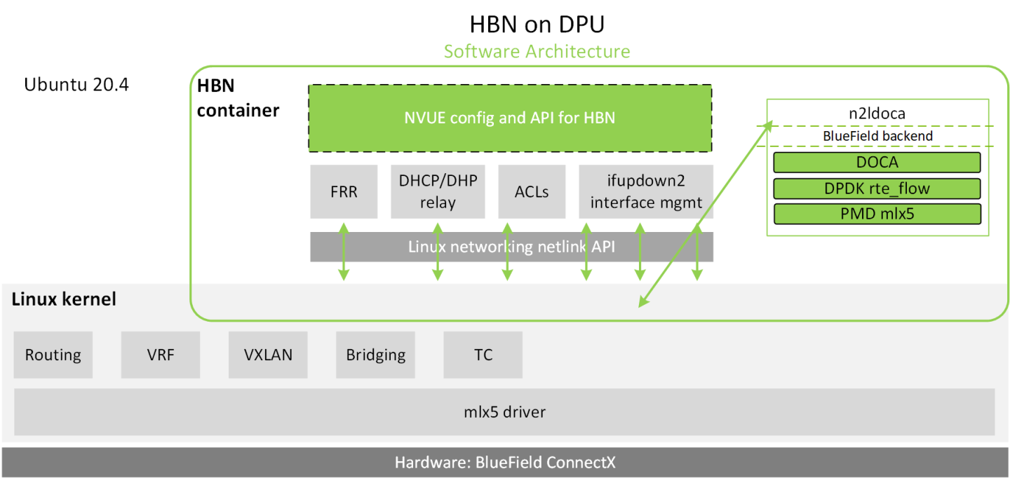
Host-based networking (HBN) is a DOCA service that enables the network architect to design a network purely on L3 protocols, enabling routing to run on the server-side of the network by using the DPU as a BGP router. The EVPN extension of BGP, supported by HBN, extends the L3 underlay network to multi-tenant environments with overlay L2 and L3 isolated networks.
The HBN solution packages a set of network functions inside a container which, itself, is packaged as a service pod to be run on the DPU. At the core of HBN is the Linux networking DPU acceleration driver. Netlink to DOCA daemon, or nl2docad, implements the DPU acceleration driver. nl2docad seamlessly accelerates Linux networking using DPU hardware programming APIs.
The driver mirrors the Linux kernel routing and bridging tables into the DPU hardware by discovering the configured Linux networking objects using the Linux Netlink API. Dynamic network flows, as learned by the Linux kernel networking stack, are also programmed by the driver into DPU hardware by listening to Linux kernel networking events.
The following diagram captures an overview of HBN and the interactions between various components of HBN.
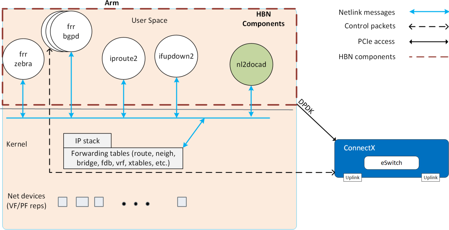
- ifupdown2 is the interface manager which pushes all the interface related states to kernel
- The routing stack is implemented in FRR and pushes all the control states (EVPN MACs and routes) to kernel via netlink
- Kernel maintains the whole network state and relays the information using netlink. The kernel is also involved in the punt path and handling traffic that does not match any rules in the eSwitch.
- nl2docad listens for the network state via netlink and invokes the DOCA interface to accelerate the flows in the DPU HW tables. nl2docad also offloads these flows to eSwitch.
3.1. Preparing DPU for HBN Deployment
HBN requires service function chaining (SFC) to be activated on the DPU before running the HBN service container. SFC allows for additional services/containers to be chained to HBN and provides additional data manipulation capabilities.
The following subsections provide additional information about SFC and instructions on enabling it during DPU BFB installation.
3.1.1. Service Function Chaining
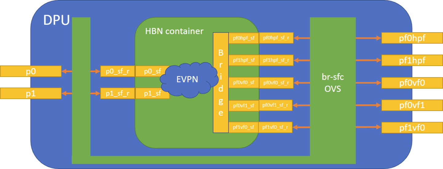
The diagram below shows the fully detailed default configuration for HBN with service function chaining (SFC). In this setup, the HBN container is configured to use sub-function ports (SFs) instead of the actual uplinks, PFs and VFs. To illustrate, for example:
- Uplinks – use
p0_sfinstead ofp0 - PF – use
pf0hpf_sfinstead ofpf0hpf - VF – use
pf0vf0_sfinstead ofpf0vf0
The indirection layer between the SF and the actual ports is managed via a br-sfc OVS bridge automatically configured when the BFB image is installed on the DPU with HBN enabled. This indirection layer allows other services to be chained to existing SFs and provide additional functionality to transit traffic.
3.1.2. Enabling SFC for HBN Deployment
3.1.2.1. Deployment from BFB
To enable HBN SFC during BFB deployment, add the following parameters to the bf.cfg configuration file:
            ENABLE_SFC_HBN=yes
NUM_SFs_ECPF0=16   # Default value for the number of VFs on PF0
NUM_SFs_ECPF1=4    # Default value for the number of VFs on PF1
Then run:
# bfb-install -c bf.cfg -r rshim0 -b <BFB-image>
3.1.2.2. Deployment from PXE
To enable HBN SFC using a PXE installation environment with BFB content, use the following configuration for PXE:
            bfnet=<IFNAME>:<IPADDR>:<NETMASK> or <IFNAME>:dhcp
bfks=<URL of the kickstart script>
The kickstart script (bash) should include the following lines:
            cat >> /etc/bf.cfg << EOF
ENABLE_SFC_HBN=yes
NUM_SFs_ECPF0=<num-of-SFs-to-prepare-for-VFs-opened-by-x86-on-PF0>
NUM_SFs_ECPF1=<num-of-SFs-to-prepare-for-VFs-opened-by-x86-on-PF1>
EOF
/etc/bf.cfg will be sourced by the BFB install.sh script.
It is recommended to verify the accuracy of the DPU's clock post-installation. This can be done using the following command:
$ date
Please refer to the known issues listed in the NVIDIA DOCA Release Notes for more information.
3.2. HBN Service Container Deployment
HBN service is available on NGC, NVIDIA's container catalog. Service-specific configuration steps and deployment instructions can be found under the service's container page. Make sure to follow the instructions in the NGC page to verify that the container is running properly.
For information about the deployment of DOCA containers on top of the BlueField DPU, refer to NVIDIA DOCA Container Deployment Guide.
3.3. HBN Default Deployment Configuration
DOCA HBN Service comes with four types of configurable interfaces:
- Two uplinks (
p0_sf,p1_sf) - Two PF port representors (
pf0hpf_sf,pf1hpf_sf) - User-defined number of VFs (i.e.,
pf0vf0_sf,pf0vf1_sf, …,pf1vf0_sf,pf1vf1_sf, …) - One interface to connect to services running on the DPU, outside of the HBN container (
dpu1_sf)
The *_sf suffix indicates that these are sub-functions and are different from the physical uplinks (i.e., PFs, VFs). They can be viewed as virtual interfaces from a virtualized DPU.
Each of these interfaces is connected outside the HBN container to the corresponding physical interface, see section Service Function Chaining (SFC) for more details.
The HBN container runs as an isolated namespace and does not see any interfaces outside the container (oob_net0, real uplinks and PFs, *_sf_r representors).
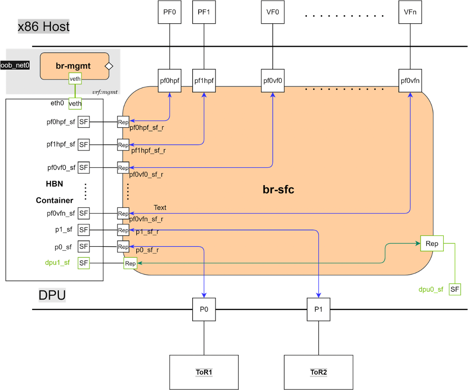
dpu1_sf is a special interface for HBN to connect to services running on the DPU. Its counterpart dpu0_sf is located outside the HBN container. See Connecting to Services on DPU for deployment considerations when using the dpu1_sf interface in HBN.
eth0 is equivalent to the oob_net0 interface in the HBN container. It is part of the management VRF of the container. It is not configurable via NVUE and does not need any configuration from the user. See TBD for more details on this interface and the management VRF.
3.4. HBN Deployment Considerations
3.4.1. SF Interface State Tracking
When HBN is deployed with SFC, the interface state of the following network devices is propagated to their corresponding SFs:
- Uplinks –
p0,p1 - PFs –
pf0hpf,pf1hpf - VFs –
pf0vfX,pf1vfXwhereXis the VF number
For example, if the p0 uplink cable gets disconnected:
p0transitions to DOWN state withNO-CARRIER(default behavior on Linux); andp0state is propagated top0_sfwhose state also becomes DOWN with NO-CARRIER
After p0 connection is reestablished:
p0transitions to UP state; andp0state is propagated top0_sfwhose state becomes UP
Interface state propagation only happens in the uplink/PF/VF-to-SF direction.
A daemon called sfc-state-propagation runs on the DPU, outside of the HBN container, to sync the state. The daemon listens to netlink notifications for interfaces and transfers the state to SFs.
3.4.2. SF Interface MTU
In the HBN container, the MTUs of all interfaces are set to 9216 by default. The MTU of specific interfaces can be overridden using flat-files configuration or NVUE.
On the DPU side (i.e., outside of the HBN container), the MTU of the uplinks, PFs, and VFs interfaces are also set to 9216. This can be changed by modifying /etc/systemd/network/30-hbn-mtu.network or by adding a new configuration file in the /etc/systemd/network for specific directories.
To reload this configuration, execute systemctl restart systemd-networkd.
3.4.3. Connecting to Services on DPU
dpu1_sf can be used by HBN to connect to services running on the DPU. Its counterpart, dpu0_sf, is located outside the HBN container.
Traffic between the DPU and the outside world is not hardware-accelerated in the HBN container when using a native L3 connection over dpu0_sf/dpu1_sf. To get hardware-acceleration, configure dpu1_sf in the HBN container with bridge-access over a switch virtual interface (SVI).
3.4.4. Disabling DPU Uplinks
The uplink ports must be always kept administratively up for proper operation of HBN. Otherwise, the NVIDIA® ConnectX® firmware would bring down the corresponding representor port which would cause data forwarding to stop.
Change in operational status of uplink (e.g., carrier down) would result in traffic being switched to the other uplink.
When using ECMP failover on the two uplink SFs, locally disabling one uplink does not result in traffic switching to the second uplink. Disabling local link in this case means to set one uplink admin DOWN directly on the DPU.
To test ECMP failover scenarios correctly, the uplink must be disabled from its remote counterpart (i.e., execute admin DOWN on the remote system's link which is connected to the uplink).
4.1. General Network Configuration
4.1.1. Flat Files Configuration
Add network interfaces and FRR configuration files on the DPU to achieve the desired configuration:
/etc/network/interfacesNote:Refer to NVIDIA® Cumulus® Linux documentation for more information.
/etc/frr/frr.conf;/etc/frr/daemonsNote:Refer to NVIDIA® Cumulus® Linux documentation for more information.
4.2. NVUE Configuration
This chapter assumes familiarity with NVIDIA user experience (NVUE) Cumulus Linux documentation. The following subsections, only expand on DPU-specific aspects of NVUE.
4.2.1. NVUE Service
HBN installs NVUE by default and enables NVUE service at boot.
4.2.2. NVUE REST API
HBN enables REST API by default.
Users may run the cURL commands from the command line. Use the default HBN username nvidia and password nvidia.
To change the default password of the nvidia user or add additional users for NVUE access, refer to NVUE User Credentials. REST API example:
            curl -u 'nvidia:nvidia' --insecure https://10.188.108.58:8765/nvue_v1/interface/p0
{
  "ip": {
    "address": {
      "30.0.0.1/24": {}
    }
  },
  "link": {
    "auto-negotiate": "on",
    "duplex": "full",
    "fec": "auto",
    "mac": "b8:ce:f6:a8:83:9a",
    "mtu": 9216,
    "speed": "100G",
    "state": {
      "up": {}
    },
    "stats": {
      "carrier-transitions": 13,
      "in-bytes": 0,
      "in-drops": 0,
      "in-errors": 0,
      "in-pkts": 0,
      "out-bytes": 14111,
      "out-drops": 0,
      "out-errors": 0,
      "out-pkts": 161
    }
  },
  "pluggable": {
    "identifier": "QSFP28",
    "vendor-name": "Mellanox",
    "vendor-pn": "MCP1600-C00AE30N",
    "vendor-rev": "A4",
    "vendor-sn": "MT2105VB02844"
  },
  "type": "swp"
}
For information about using the NVUE REST API, refer to the NVUE API documentation.
4.2.3. NVUE CLI
For information about using the NVUE CLI, refer to the NVUE CLI documentation.
4.2.4. NVUE Startup Configuration File
When the network configuration is saved using NVUE, HBN writes the configuration to the /etc/nvue.d/startup.yaml file.
Startup configuration is applied by following the supervisor daemon at boot time. nvued-startup will appear in EXITED state after applying the startup configuration.
            # supervisorctl status nvued-startup
nvued-startup                    EXITED    Apr 17 10:04 AM
nv config apply startup applies the yaml configuration saved at /etc/nvue.d/.
nv config save saves the running configuration to /etc/nvue.d/startup.yaml.
4.2.5. NVUE User Credentials
NVUE user credentials can be added post installation. This functionality is enabled by the HBN startup script by using the –-username and –-password script switches. For example:
./hbn-dpu-setup.sh -u newuser -p newpassword
After executing this script, respawn the container or start the decrypt-user-add script:
            supervisorctl start decrypt-user-add
decrypt-user-add: started
The script creates a user on the HBN container:
            cat /etc/passwd | grep newuser
newuser:x:1001:1001::/home/newuser:/bin/bash
4.2.6. NVUE Interface Classification
| Interface | Interface Type | NVUE Type | Comment |
|---|---|---|---|
| p0_sf | Uplink representor | swp | Use type swp |
| p1_sf | Uplink representor | swp | Use type swp |
| lo | Loopback | loopback | Tested with NVUE |
| pf0hpf_sf | Host representor | swp | Use type swp |
| pf1hpf_sf | Host representor | swp | Use type swp |
| pf0vfx_sf (where x is 0 to 255) | VF representor | swp | Use type swp |
| pf1vfx_sf (where x is 0 to 255) | VF representor | swp | Use type swp |
4.3. Configuration Persistence
The following directories are mounted from the host DPU to the HBN container and are persistent across HBN restarts and DPU reboots:
| Host DPU Mount Point | HBN Container Mount Point |
|---|---|
| Configuration Files Mount Pints | |
| /var/lib/hbn/etc/network/ | /etc/network/ |
| /var/lib/hbn/etc/frr/ | /etc/frr/ |
| /var/lib/hbn/etc/nvue.d/ | /etc/nvue.d/ |
| /var/lib/hbn/etc/supervisor/conf.d/ | /etc/supervisor/conf.d/ |
| /var/lib/hbn/var/lib/nvue/ | /var/lib/nvue/ |
| Support and Log Files Mount Points | |
| /var/lib/hbn/var/support/ | /var/support/ |
| /var/log/doca/hbn/ | /var/log/hbn/ |
4.4. SR-IOV Support
4.4.1. Creating VFs on Host Server
The first step to use SR-IOV is to create VFs on the host server. VFs can be created using the following command:
echo N > /sys/class/net/<host-rep>/device/sriov_numvfs
Where:
<host-rep>is one of the two host representors (e.g.,ens1f0orens1f1)- 0≤
N≤16 is the desired total number of VFs- Set
N=0 to delete all the VFs on 0≤N≤16 N=16 is the maximum number of VFs supported on HBN across all representors
- Set
4.4.2. Automatic Creation of VF Representors on DPU
VFs created on the host must have corresponding SF representors on the DPU side. For example:
ens1f0vf0is the first VF from the first host representor; this interface is created on the host serverpf0vf0is the corresponding VF representor toens1f0vf0; this interface is on the DPU and automatically created at the same time asen1sf0vf0is createdpf0vf0_sfis the corresponding SF forpf0vf0which is used by HBN
The creation of the SF representor for VFs is done ahead of time when installing the BFB, see section Enabling SFC for HBN DeploymentService Deployment to see how to select how many SFs to create ahead of time.
The SF representors for VFs (i.e., pfXvfY) are pre-mapped to work with the corresponding VF representors when these are created with the command from section Creating VFs on Host Server.
4.5. Management VRF
Two management VRFs are setup for HBN with SFC:
- The first management VRF is outside the HBN container on the DPU. This VRF provides separation between out-of-band (OOB) traffic (via
oob_net0ortmfifo_net0) and data-plane traffic via uplinks and PFs. - The second management VRF is inside the HBN container and provides similar separation. The OOB traffic (via
eth0) is isolated from the traffic via the*_sfinterfaces.
4.5.1. MGMT VRF on Host DPU
The management (mgmt) VRF is enabled by default when the DPU is deployed with SFC (see Enabling SFC for HBN Deployment). The mgmt VRF provides separation between the out-of-band management network and the in-band data plane network.
The uplinks and PFs/SFs/VFs use the default routing table while the oob_net0 (out-of-band Ethernet port) and the tmifo_net0 netdevices use the mgmt VRF to route their packets.
When logging in either via SSH or the console, the shell is by default in mgmt VRF context. This is indicated by a mgmtadded to the shell prompt:
root@bf2:mgmt:/home/ubuntu#
When logging into the HBN container with crictl, the HBN shell will be in the default VRF. Users must switch to mgmt VRF manually if out-of-band access is required. Use ip vrf exec to do so.
root@bf2:mgmt:/home/ubuntu# ip vrf exec mgmt bash
The user must run ip vrf exec mgmt to perform other operations (e.g., apt-get update).
Network devices belonging to the mgmt VRF can be listed with the vrf utility:
            root@bf2:mgmt:/home/ubuntu# vrf link list

VRF: mgmt
--------------------
tmfifo_net0      UP             00:1a:ca:ff:ff:03 <BROADCAST,MULTICAST,UP,LOWER_UP>
oob_net0         UP             08:c0:eb:c0:5a:32 <BROADCAST,MULTICAST,UP,LOWER_UP>

root@bf2:mgmt:/home/ubuntu# vrf help
vrf <OPTS>

VRF domains:
    vrf list

Links associated with VRF domains:
    vrf link list [<vrf-name>]

Tasks and VRF domain asociation:
    vrf task exec <vrf-name> <command>
    vrf task list [<vrf-name>]
    vrf task identify <pid>

    NOTE: This command affects only AF_INET and AF_INET6 sockets opened by the
          command that gets exec'ed. Specifically, it has *no* impact on netlink          sockets (e.g., ip command).
To show the routing table for the default VRF, run:
root@bf2:mgmt:/home/ubuntu# ip route show
To show the routing table for the mgmt VRF, run:
root@bf2:mgmt:/home/ubuntu# ip route show vrf mgmt
4.5.2. MGMT VRF in HBN Container
Inside the HBN container, a separate mgmt VRF is present. Similar commands as those listed under MGMT VRF on Host DPU can be used to query management routes.
The *_sf interfaces use the default routing table while the eth0 (OOB) uses the mgmt VRF to route out-of-band packets out of the container. The OOB traffic gets NATed through the DPU oob_net0 interface, ultimately using the DPU OOB's IP address.
When logging into the HBN container via crictl, the shell enters the default VRF context by default. Switching to the mgmt VRF can be done using the command ip vrf exec mgmt <cmd>.
4.5.3. Existing Services in MGMT VRF on Host DPU
On the host DPU, outside the HBN container, a set of existing services run in the mgmt VRF context as they need OOB network access:
- containerd
- kubelet
- ssh
- docker
These services can be restarted and queried for their status using the command systemctl while adding @mgmt to the original service name. For example:
- To restart containerd:
root@bf2:mgmt:/home/ubuntu# systemctl restart containerd@mgmt
- To query containerd status:
root@bf2:mgmt:/home/ubuntu# systemctl status containerd@mgmt
4.5.4. Running New Service in MGMT VRF
If a service needs OOB access to run, it can be added to the set of services running in mgmt VRF context. Adding such a service is only possible on the host DPU (i.e., outside the HBN container). To add a service to the set of MGMT VRF services:
- Add it to
/etc/vrf/systemd.conf(if it is not present already). For example, NTP is already listed in this file. - Run the following:
root@bf2:mgmt:/home/ubuntu# systemctl daemon-reload
- Stop and disable to the non-VRF version of the service to be able to start the mgmt VRF one:
            root@bf2:mgmt:/home/ubuntu# systemctl stop ntp
root@bf2:mgmt:/home/ubuntu# systemctl disable ntp
root@bf2:mgmt:/home/ubuntu# systemctl enable ntp@mgmt
root@bf2:mgmt:/home/ubuntu# systemctl start ntp@mgmt
4.6. HBN Configuration Examples
4.6.1. HBN Default Configuration
After a fresh HBN installation, the default /etc/network/interfaces file would contain only the declaration of the two uplink SFs and a default bridge to which interfaces can be added manually or via NVUE.
            auto p0_sf
iface p0_sf

auto p1_sf
iface p1_sf

auto br_default
iface br_default
    bridge-vlan-aware yes
FRR configuration files would also be present under /etc/frr/ but no configuration would be enabled.
4.6.2. Native Routing with BGP and ECMP
HBN supports unicast routing with BGP and ECMP for IPv4 and IPv6 traffic. ECMP is achieved by distributing traffic per destination prefix in a round-robin fashion.
4.6.2.1. ECMP Configuration
ECMP is implemented any time routes have multiple paths over uplinks. For example:
            20.20.20.0/24 proto bgp metric 20
	nexthop via 169.254.0.1 dev p0_sf weight 1 onlink <<<<< via uplink p0_sf
	nexthop via 169.254.0.1 dev p1_sf weight 1 onlink <<<<< via uplink p1_sf
4.6.2.1.1. Sample NVUE Configuration
            nv set interface lo ip address 10.10.10.1/32
nv set interface lo ip address 2010:10:10::1/128
nv set interface vlan100 type svi
nv set interface vlan100 vlan 100
nv set interface vlan100 base-interface br_default
nv set interface vlan100 ip address 2030:30:30::1/64
nv set interface vlan100 ip address 30.30.30.1/24
nv set bridge domain br_default vlan 100
nv set interface pf0hpf_sf,pf1hpf_sf bridge domain br_default
nv set vrf default router bgp router-id 10.10.10.1
nv set vrf default router bgp autonomous-system 65501
nv set vrf default router bgp path-selection multipath aspath-ignore on
nv set vrf default router bgp address-family ipv4-unicast enable on
nv set vrf default router bgp address-family ipv4-unicast redistribute connected enable on
nv set vrf default router bgp address-family ipv6-unicast enable on
nv set vrf default router bgp address-family ipv6-unicast redistribute connected enable on
nv set vrf default router bgp neighbor p0_sf remote-as external
nv set vrf default router bgp neighbor p0_sf type unnumbered
nv set vrf default router bgp neighbor p0_sf address-family ipv4-unicast enable on
nv set vrf default router bgp neighbor p0_sf address-family ipv6-unicast enable on
nv set vrf default router bgp neighbor p1_sf remote-as external
nv set vrf default router bgp neighbor p1_sf type unnumbered
nv set vrf default router bgp neighbor p1_sf address-family ipv4-unicast enable on
nv set vrf default router bgp neighbor p1_sf address-family ipv6-unicast enable on
4.6.2.1.2. Sample Flat Files Configuration
Example /etc/network/interfaces configuration:
            auto lo
iface lo inet loopback
    address 10.10.10.1/32
    address 2010:10:10::1/128

auto p0_sf
iface p0_sf

auto p1_sf
iface p1_sf

auto pf0hpf_sf
iface pf0hpf_sf

auto pf1hpf_sf
iface pf1hpf_sf

auto vlan100
iface vlan100
    address 2030:30:30::1/64
    address 30.30.30.1/24
    vlan-raw-device br_default
    vlan-id 100

auto br_default
iface br_default
    bridge-ports pf0hpf_sf pf1hpf_sf
    bridge-vlan-aware yes
    bridge-vids 100
    bridge-pvid 1
Example /etc/frr/daemons configuration:
            bgpd=yes
vtysh_enable=yes


FRR Config file @ /etc/frr/frr.conf -
!
frr version 7.5+cl5.3.0u0
frr defaults datacenter
hostname BLUEFIELD2
log syslog informational
no zebra nexthop kernel enable
!
router bgp 65501
 bgp router-id 10.10.10.1
 bgp bestpath as-path multipath-relax
 neighbor p0_sf interface remote-as external
 neighbor p0_sf advertisement-interval 0
 neighbor p0_sf timers 3 9
 neighbor p0_sf timers connect 10
 neighbor p1_sf interface remote-as external
 neighbor p1_sf advertisement-interval 0
 neighbor p1_sf timers 3 9
 neighbor p1_sf timers connect 10
 !
 address-family ipv4 unicast
  redistribute connected
  maximum-paths 64
  maximum-paths ibgp 64
 exit-address-family
 !
 address-family ipv6 unicast
  redistribute connected
  neighbor p0_sf activate
  neighbor p1_sf activate
  maximum-paths 64
  maximum-paths ibgp 64
 exit-address-family
!
line vty
!
end
4.6.2.2. BGP Peering with Host
HBN supports the ability to establish a BGP session between the host and DPU and allow the host to announce arbitrary route prefixes through the DPU into the underlay fabric. The host can use any standard BGP protocol stack implementation to establish BGP peering with HBN.
It is possible to apply route filtering for these prefixes to limit the potential security impact in this configuration.
4.6.2.2.1. Sample NVUE Configuration
The following code block shows configuration to peer to host at 45.3.0.4 and 2001:cafe:1ead::4. The BGP session can be established using IPv4 or IPv6 address.
NVUE configuration for peering with host:
            nv set vrf default router bgp autonomous-system 63642
nv set vrf default router bgp enable on
nv set vrf default router bgp neighbor 45.3.0.4 nexthop-connected-check off
nv set vrf default router bgp neighbor 45.3.0.4 peer-group dpu_host
nv set vrf default router bgp neighbor 45.3.0.4 type numbered
nv set vrf default router bgp neighbor 2001:cafe:1ead::4 nexthop-connected-check off
nv set vrf default router bgp neighbor 2001:cafe:1ead::4 peer-group dpu_host
nv set vrf default router bgp neighbor 2001:cafe:1ead::4 type numbered
nv set vrf default router bgp peer-group dpu_host address-family ipv4-unicast enable on
nv set vrf default router bgp peer-group dpu_host address-family ipv6-unicast enable on
nv set vrf default router bgp peer-group dpu_host remote-as external
4.6.2.2.2. Sample Flat Files Configuration
The following block shows configuration to peer to host at 45.3.0.4 and 2001:cafe:1ead::4. The BGP session can be established using IPv4 or IPv6 address.
frr.conf file:
            router bgp 63642
 bgp router-id 27.0.0.4
 bgp bestpath as-path multipath-relax
 neighbor dpu_host peer-group
 neighbor dpu_host remote-as external
 neighbor dpu_host bfd 3 1000 1000
 neighbor dpu_host advertisement-interval 0
 neighbor dpu_host timers 3 9
 neighbor dpu_host timers connect 10
 neighbor fabric peer-group
 neighbor fabric remote-as external
 neighbor fabric bfd 3 1000 1000
 neighbor fabric advertisement-interval 0
 neighbor fabric timers 3 9
 neighbor fabric timers connect 10
 neighbor 45.3.0.4 peer-group dpu_host
 neighbor 45.3.0.4 disable-connected-check
 neighbor 45.3.0.4 advertisement-interval 0
 neighbor 45.3.0.4 timers 3 9
 neighbor 45.3.0.4 timers connect 10
 neighbor 2001:cafe:1ead::4 peer-group dpu_host
 neighbor 2001:cafe:1ead::4 disable-connected-check
 neighbor 2001:cafe:1ead::4 advertisement-interval 0
 neighbor 2001:cafe:1ead::4 timers 3 9
 neighbor 2001:cafe:1ead::4 timers connect 10
 neighbor p0_sf interface peer-group fabric
 neighbor p0_sf advertisement-interval 0
 neighbor p0_sf timers 3 9
 neighbor p0_sf timers connect 10
 neighbor p1_sf interface peer-group fabric
 neighbor p1_sf advertisement-interval 0
 neighbor p1_sf timers 3 9
 neighbor p1_sf timers connect 10
 !
 address-family ipv4 unicast
neighbor dpu_host activate
!
 address-family ipv6 unicast
neighbor dpu_host activate
4.6.2.2.3. Sample Configuration on Host Running FRR
Any BGP implementation can be used on the host to peer to HBN and advertise endpoints. The following is an example using FRR BGP.
- Sample FRR configuration on the host:
            bf2-s12# sh run
Building configuration...

Current configuration:
!
frr version 7.2.1
frr defaults traditional
hostname bf2-s12
no ip forwarding
no ipv6 forwarding
!
router bgp 1000008
!
router bgp 1000008 vrf v_200_2000
 neighbor 45.3.0.2 remote-as external
 neighbor 2001:cafe:1ead::2 remote-as external
 !
 address-family ipv4 unicast
  redistribute connected
 exit-address-family
 !
 address-family ipv6 unicast
  redistribute connected
  neighbor 45.3.0.2 activate
  neighbor 2001:cafe:1ead::2 activate
 exit-address-family
!
line vty
!
end
- Sample FRR configuration on host:
            bf2-s12# sh run
Building configuration...

Current configuration:
!
frr version 7.2.1
frr defaults traditional
hostname bf2-s12
no ip forwarding
no ipv6 forwarding
!
router bgp 1000008
!
router bgp 1000008 vrf v_200_2000
 neighbor 45.3.0.2 remote-as external
 neighbor 2001:cafe:1ead::2 remote-as external
 !
 address-family ipv4 unicast
  redistribute connected
 exit-address-family
 !
 address-family ipv6 unicast
  redistribute connected
  neighbor 45.3.0.2 activate
  neighbor 2001:cafe:1ead::2 activate
 exit-address-family
!
line vty
!
end
- Sample interface configuration on the host:
            root@bf2-s12:/home/cumulus# ifquery -a
auto lo
iface lo inet loopback
	address 27.0.0.7/32
	address 2001:c15c:d06:f00d::7/128
auto v_200_2000
iface v_200_2000
	address 60.1.0.1
	address 60.1.0.2
	address 60.1.0.3
    address 2001:60:1::1
	address 2001:60:1::2
	address 2001:60:1::3
    vrf-table auto
auto ens1f0np0
iface ens1f0np0
	address 45.3.0.4/24
	address 2001:cafe:1ead::4/64
	gateway 45.3.0.1
	gateway 2001:cafe:1ead::1
	vrf v_200_2000
	hwaddress 00:03:00:08:00:12
	mtu 9162
4.6.3. L2 EVPN with BGP and ECMP
HBN supports VXLAN with EVPN control plane for intra-subnet bridging (L2) services for IPv4 and IPv6 traffic in the overlay.
For the underlay, only IPv4 or BGP unnumbered configuration is supported.
The following is a sample config which has L2-VNIs (vx-2000, vx-2001) for EVPN bridging.
4.6.3.1. Single VXLAN Device
With a single VXLAN device, a set of VNIs represents a single device model. The single VXLAN device has a set of attributes that belong to the VXLAN construct. Individual VNIs include VLAN-to-VNI mapping which allows users to specify which VLANs are associated with which VNIs. A single VXLAN device simplifies the configuration and reduces the overhead by replacing multiple traditional VXLAN devices with a single VXLAN device.
Users may configure a single VXLAN device automatically with NVUE, or manually by editing the /etc/network/interfaces file. When users configure a single VXLAN device with NVUE, NVUE creates a unique name for the device in the following format using the bridge name as the hash key: vxlan<id>.
This example configuration performs the following steps:
- Creates a single VXLAN device (vxlan21).
- Maps VLAN 10 to VNI 10 and VLAN 20 to VNI 20.
- Adds the VXLAN device to the default bridge.
            cumulus@leaf01:~$ nv set bridge domain bridge vlan 10 vni 10
cumulus@leaf01:~$ nv set bridge domain bridge vlan 20 vni 20
cumulus@leaf01:~$ nv set nve vxlan source address 10.10.10.1
cumulus@leaf01:~$ nv config apply
Alternately, users may edit the file /etc/network/interfaces as follows, then run the ifreload -a command to apply the SVD configuration.
            auto lo
iface lo inet loopback
    vxlan-local-tunnelip 10.10.10.1

auto vxlan21
iface vxlan21
    bridge-vlan-vni-map 10=10 20=20
    bridge-learning off

auto bridge
iface bridge
    bridge-vlan-aware yes
    bridge-ports vxlan21 pf0hpf_sf pf1hpf_sf
    bridge-vids 10 20
    bridge-pvid 1
Users may not use a combination of single and traditional VXLAN devices.
4.6.3.2. Sample NVUE Configuration
            nv set bridge domain br_default encap 802.1Q
nv set bridge domain br_default type vlan-aware
nv set bridge domain br_default vlan 200 vni 2000 flooding enable auto
nv set bridge domain br_default vlan 200 vni 2000 mac-learning off
nv set bridge domain br_default vlan 201 vni 2001 flooding enable auto
nv set bridge domain br_default vlan 201 vni 2001 mac-learning off

nv set evpn enable on
nv set nve vxlan arp-nd-suppress on
nv set nve vxlan enable on
nv set nve vxlan mac-learning off
nv set nve vxlan source address 27.0.0.4
nv set platform
nv set router bgp enable on
nv set system global anycast-mac 44:38:39:42:42:07
nv set vrf default router bgp address-family ipv4-unicast enable on
nv set vrf default router bgp address-family ipv4-unicast redistribute connected enable on

nv set vrf default router bgp address-family l2vpn-evpn enable on
nv set vrf default router bgp autonomous-system 63642
nv set vrf default router bgp enable on
nv set vrf default router bgp neighbor p0_sf peer-group fabric
nv set vrf default router bgp neighbor p0_sf type unnumbered
nv set vrf default router bgp neighbor p1_sf peer-group fabric
nv set vrf default router bgp neighbor p1_sf type unnumbered
nv set vrf default router bgp path-selection multipath aspath-ignore on
nv set vrf default router bgp peer-group fabric address-family ipv4-unicast enable on
nv set vrf default router bgp peer-group fabric address-family ipv4-unicast policy outbound route-map MY_ORIGIN_ASPATH_ONLY
nv set vrf default router bgp peer-group fabric address-family ipv6-unicast enable on
nv set vrf default router bgp peer-group fabric address-family ipv6-unicast policy outbound route-map MY_ORIGIN_ASPATH_ONLY
nv set vrf default router bgp peer-group fabric address-family l2vpn-evpn add-path-tx off
nv set vrf default router bgp peer-group fabric address-family l2vpn-evpn enable on
nv set vrf default router bgp peer-group fabric remote-as external
nv set vrf default router bgp router-id 27.0.0.4

nv set interface lo ip address 2001:c15c:d06:f00d::4/128
nv set interface lo ip address 27.0.0.4/32
nv set interface lo type loopback
nv set interface p0_sf,p1_sf,pf0hpf_sf,pf0vf0__sf,pf1hpf_sf type swp
nv set interface pf0hpf_sf bridge domain br_default access 200
nv set interface pf0vf0_sf bridge domain br_default access 201

nv set interface vlan200-217 base-interface br_default
nv set interface vlan200-217 ip ipv4 forward on
nv set interface vlan200-217 ip ipv6 forward on
nv set interface vlan200-217 ip vrr enable on
nv set interface vlan200-217 ip vrr state up
nv set interface vlan200-217 link mtu 9050
nv set interface vlan200-217 type svi
nv set interface vlan200 ip address 2001:cafe:1ead::3/64
nv set interface vlan200 ip address 45.3.0.2/24
nv set interface vlan200 ip vrr address 2001:cafe:1ead::1/64
nv set interface vlan200 ip vrr address 45.3.0.1/24
nv set interface vlan200 vlan 200
nv set interface vlan201 ip address 2001:cafe:1ead:1::3/64
nv set interface vlan201 ip address 45.3.1.2/24
nv set interface vlan201 ip vrr address 2001:cafe:1ead:1::1/64
nv set interface vlan201 ip vrr address 45.3.1.1/24
nv set interface vlan201 vlan 201
4.6.3.3. Sample Flat Files Configuration
This file is located at /etc/network/interfaces:
            auto lo
iface lo inet loopback
    address 2001:c15c:d06:f00d::4/128
    address 27.0.0.4/32
    vxlan-local-tunnelip 27.0.0.4

auto p0_sf
iface p0_sf

auto p1_sf
iface p1_sf

auto pf0hpf_sf
iface pf0hpf_sf
    bridge-access 200

auto pf0vf0_sf
iface pf0vf0_sf
    bridge-access 201

auto pf1hpf_sf
iface pf1hpf_sf
    bridge-access 217

auto vlan200
iface vlan200
    address 2001:cafe:1ead::3/64
    address 45.3.0.2/24
    mtu 9050
    address-virtual 00:00:5e:00:01:01 2001:cafe:1ead::1/64 45.3.0.1/24
    vlan-raw-device br_default
    vlan-id 200

auto vlan201
iface vlan201
    address 2001:cafe:1ead:1::3/64
    address 45.3.1.2/24
    mtu 9050
    address-virtual 00:00:5e:00:01:01 2001:cafe:1ead:1::1/64 45.3.1.1/24
    vlan-raw-device br_default
    vlan-id 201

auto vxlan48
iface vxlan48
    bridge-vlan-vni-map 200=2000 201=2001
217=2017
    bridge-learning off

auto br_default
iface br_default
    bridge-ports pf0hpf_sf pf0vf0_sf
hpf_sf vxlan48
    bridge-vlan-aware yes
    bridge-vids 200 201 202 203 204 205 206 207 208 209 210 211 212 213 214 215 216 217
    bridge-pvid 1
This file, which tells the frr package which daemon to start, is located at /etc/frr/daemons:
            bgpd=yes
ospfd=no
ospf6d=no
isisd=no
pimd=no
ldpd=no
pbrd=no
vrrpd=no
fabricd=no
nhrpd=no
eigrpd=no
babeld=no
sharpd=no
fabricd=no
ripngd=no
ripd=no

vtysh_enable=yes
zebra_options="  -M cumulus_mlag -M snmp -A 127.0.0.1 -s 90000000"
bgpd_options="   -M snmp -A 127.0.0.1"
ospfd_options="  -M snmp -A 127.0.0.1"
ospf6d_options=" -M snmp -A ::1"
ripd_options="   -A 127.0.0.1"
ripngd_options=" -A ::1"
isisd_options="  -A 127.0.0.1"
pimd_options="   -A 127.0.0.1"
ldpd_options="   -A 127.0.0.1"
nhrpd_options="  -A 127.0.0.1"
eigrpd_options=" -A 127.0.0.1"
babeld_options=" -A 127.0.0.1"
sharpd_options=" -A 127.0.0.1"
pbrd_options="   -A 127.0.0.1"
staticd_options="-A 127.0.0.1"
fabricd_options="-A 127.0.0.1"
vrrpd_options="  -A 127.0.0.1"

frr_profile="datacenter"
This file is located at /etc/frr/frr.conf:
            !---- Cumulus Defaults ----
frr defaults datacenter
log syslog informational
no zebra nexthop kernel enable
vrf default
outer bgp 63642 vrf default
bgp router-id 27.0.0.4
bgp bestpath as-path multipath-relax
timers bgp 3 9
bgp deterministic-med
! Neighbors
neighbor fabric peer-group
neighbor fabric remote-as external
neighbor fabric timers 3 9
neighbor fabric timers connect 10
neighbor fabric advertisement-interval 0
no neighbor fabric capability extended-nexthop
neighbor p0_sf interface peer-group fabric
neighbor p0_sf timers 3 9
neighbor p0_sf timers connect 10
neighbor p0_sf advertisement-interval 0
neighbor p0_sf capability extended-nexthop
neighbor p0_sf bfd
neighbor p1_sf interface peer-group fabric
neighbor p1_sf timers 3 9
neighbor p1_sf timers connect 10
neighbor p1_sf advertisement-interval 0
neighbor p1_sf capability extended-nexthop
maximum-paths ibgp 64
maximum-paths 64
distance bgp 20 200 200
neighbor fabric activate
neighbor p0_sf activate
neighbor p1_sf activate
exit-address-family
address-family ipv6 unicast
maximum-paths ibgp 64
maximum-paths 64
distance bgp 20 200 200
neighbor fabric activate
neighbor p0_sf activate
neighbor p1_sf activate
exit-address-family
address-family l2vpn evpn
advertise-all-vni
neighbor fabric activate
neighbor p0_sf activate
neighbor p1_sf activate
exit-address-family
4.6.4. Access Control Lists
4.6.4.1. Stateless ACLs
The following tools administer filtering rules:
- IPTABLES – filtering rules for IPv4 packets
- EBTABLES – filtering rules for Ethernet frames
- IP6TABLES – filtering rules for IPv6 packets
4.6.4.1.1. NVUE Examples
NVUE IPv4 ACLs Example
The following is an example of an ingress IPv4 ACL that permits DHCP request packets ingressing on the pf0hpf_sf port towards the DHCP server:
            root@hbn01-host01:~# nv set acl acl1_ingress type ipv4
root@hbn01-host01:~# nv set acl acl1_ingress rule 100 match ip protocol udp
root@hbn01-host01:~# nv set acl acl1_ingress rule 100 match ip dest-port 67
root@hbn01-host01:~# nv set acl acl1_ingress rule 100 match ip source-port 68
root@hbn01-host01:~# nv set acl acl1_ingress rule 100 action permit
Bind the ingress IPv4 ACL to host representor port pf0hpf_sf of the DPU in the inbound direction:
            root@hbn01-host01:~# nv set interface pf0hpf_sf acl acl1_ingress inbound
root@hbn01-host01:~# nv config apply
The following is an example of an egress IPv4 ACL that permits DHCP reply packets egressing out of the pf0hpf_sf port towards the DHCP client:
            root@hbn01-host01:~# nv set acl acl2_egress type ipv4
root@hbn01-host01:~# nv set acl acl2_egress rule 100 match ip protocol udp
root@hbn01-host01:~# nv set acl acl2_egress rule 100 match ip dest-port 68
root@hbn01-host01:~# nv set acl acl2_egress rule 100 match ip source-port 67
root@hbn01-host01:~# nv set acl acl2_egress rule 100 action permit
Bind the egress IPv4 ACL to host representor port pf0hpf_sf of the DPU in the outbound direction:
            root@hbn01-host01:~# nv set interface pf0hpf_sf acl acl2_egress outbound
root@hbn01-host01:~# nv config apply
NVUE IPv6 ACLs Example
The following is an example of an ingress IPv6 ACL that permits traffic with matching dest-ip and protocoltcp ingress on port pf0hpf_sf:
            root@hbn01-host01:~# nv set acl acl5_ingress type ipv6
root@hbn01-host01:~# nv set acl acl5_ingress rule 1 match ip protocol tcp
root@hbn01-host01:~# nv set acl acl5_ingress rule 1 match ip dest-ip 48:2034::80:9
root@hbn01-host01:~# nv set acl acl5_ingress rule 1 action permit
Bind the ingress IPv6 ACL to host representor port pf0hpf_sf of the DPU in the inbound direction:
            root@hbn01-host01:~# nv set interface pf0hpf_sf acl acl5_ingress inbound
root@hbn01-host01:~# nv config apply
The following is an example of an egress IPv6 ACL that permits traffic with matching source-ip and protocol tcp egressing out of port pf0hpf_sf:
            root@hbn01-host01:~# nv set acl acl6_egress type ipv6
root@hbn01-host01:~# nv set acl acl6_egress rule 1 match ip protocol tcp
root@hbn01-host01:~# nv set acl acl6_egress rule 1 match ip source-ip 48:2034::80:9
root@hbn01-host01:~# nv set acl acl6_egress rule 1 action permit
Bind the egress IPv6 ACL to host representor port pf0hpf_sf of the DPU in the outbound direction:
            root@hbn01-host01:~# nv set interface pf0hpf_sf acl acl6_egress outbound
root@hbn01-host01:~# nv config apply
NVUE L2 ACLs Example
The following is an example of an ingress MAC ACL that permits traffic with matching source-mac and dest-mac ingressing to port pf0hpf_sf:
            root@hbn01-host01:~# nv set acl acl3_ingress type mac
root@hbn01-host01:~# nv set acl acl3_ingress rule 1 match mac source-mac 00:00:00:00:00:0a
root@hbn01-host01:~# nv set acl acl3_ingress rule 1 match mac dest-mac 00:00:00:00:00:0b
root@hbn01-host01:~# nv set interface pf0hpf_sf acl acl3_ingress inbound
Bind the ingress MAC ACL to host representor port pf0hpf_sf of the DPU in the inbound direction:
            root@hbn01-host01:~# nv set interface pf0hpf_sf acl acl3_ingress inbound
root@hbn01-host01:~# nv config apply
The following is an example of an egress MAC ACL that permits traffic with matching source-mac and dest-mac egressing out of port pf0hpf_sf:
            root@hbn01-host01:~# nv set acl acl4_egress type mac
root@hbn01-host01:~# nv set acl acl4_egress rule 1 match mac source-mac 00:00:00:00:00:0b
root@hbn01-host01:~# nv set acl acl4_egress rule 1 match mac dest-mac 00:00:00:00:00:0a
root@hbn01-host01:~# nv set acl acl4_egress rule 1 action permit
Bind the egress MAC ACL to host representor port pf0hpf_sf of the DPU in the outbound direction:
            root@hbn01-host01:~# nv set interface pf0hpf_sf acl acl4_egress outbound
root@hbn01-host01:~# nv config apply
4.6.4.1.2. Flat Files (cl-acltool) Examples
For the same example cited above, the following are the corresponding ACL rules which must be configured under /etc/cumulus/acl/policy.d/<rule_name.rules> followed by invoking cl-acltool -i.
Flat Files IPv4 ACLs Example
The following example configures an ingress IPv4 ACL rule matching with DHCP request under /etc/cumulus/acl/policy.d/<rule_name.rules> with the ingress interface as the host representor of the DPU followed by invoking cl-acltool -i:
            [iptables]
## ACL acl1_ingress in dir inbound on interface pf0hpf_sf ##
-t filter -A FORWARD -i pf1vf1_sf -p udp --sport 68 --dport 67 -m mark --mark 888 -m comment --comment "priority:1" -j ACCEPT
The following example configures an egress IPv4 ACL rule matching with DHCP reply under /etc/cumulus/acl/policy.d/<rule_name.rules> with the egress interface as the host representor of the DPU followed by invoking cl-acltool -i:
            [iptables]
## ACL acl2_egress in dir outbound on interface pf0hpf_sf ##
-t filter -A FORWARD -o pf0hpf_sf -p udp --sport 67 --dport 68 -m mark --mark 777 -m comment --comment "priority:1" -j ACCEPT
Flat File IPv6 ACLs Example
The following example configures an ingress IPv6 ACL rule matching with dest-ip and tcp protocol under /etc/cumulus/acl/policy.d/<rule_name.rules> with the ingress interface as the host representor of the DPU followed by invoking cl-acltool -i:
            [ip6tables]
## ACL acl5_ingress in dir inbound on interface pf0hpf_sf ##
-t filter -A FORWARD -i pf0hpf_sf -d 48:2034::80:9 -p tcp -m comment --comment "priority:1" -j ACCEPT
The following example configures an egress IPv6 ACL rule matching with source-ip and tcp protocol under /etc/cumulus/acl/policy.d/<rule_name.rules> with the egress interface as the host representor of the DPU followed by invoking cl-acltool -i:
            [ip6tables]
## ACL acl6_egress in dir outbound on interface pf0hpf_sf ##
-t filter -A FORWARD -o pf0hpf_sf -s 48:2034::80:9 -p tcp -m comment --comment "priority:1" -j ACCEPT
Flat Files L2 ACLs Example
The following example configures an ingress MAC ACL rule matching with source-mac and dest-mac under /etc/cumulus/acl/policy.d/<rule_name.rules> with the ingress interface as the host representor of the DPU followed by invoking cl-acltool -i:
            [ebtables]
## ACL acl3_ingress in dir inbound on interface pf0hpf_sf ##
-t filter -A FORWARD -i pf0hpf_sf -s 00:00:00:00:00:0a/ff:ff:ff:ff:ff:ff -d 00:00:00:00:00:0b/ff:ff:ff:ff:ff:ff -j ACCEPT
The following example configures an egress MAC ACL rule matching with source-mac and dest-mac under /etc/cumulus/acl/policy.d/<rule_name.rules> with egress interface as host representor of DPU followed by invoking cl-acltool -i:
            [ebtables]
## ACL acl4_egress in dir outbound on interface pf0hpf_sf ##
-t filter -A FORWARD -o pf0hpf_sf -s 00:00:00:00:00:0b/ff:ff:ff:ff:ff:ff -d 00:00:00:00:00:0a/ff:ff:ff:ff:ff:ff -j ACCEPT
4.6.4.2. Stateful ACLs
Stateful ACLs facilitate monitoring and tracking traffic flows to enforce per-flow traffic filtering (unlike stateless ACLs which filter traffic on a per-packet basis). HBN supports stateful ACLs using reflexive ACL mechanism. Reflexive ACL mechanism is used to permit initiation of connections from within the network to outside the network and allow only replies to the initiated connections from outside the network. Stateful ACLs in HBN are disabled by default. To enable stateful ACL functionality, use the following NVUE commands:
            root@hbn03-host00:~# nv set system reflexive-acl enable
root@hbn03-host00:~# nv config apply
If using flat-file configuration (and not NVUE), edit the file /etc/cumulus/nl2docad.d/acl.conf and set the knob rflx.reflexive_acl_enable to TRUE. To apply this change, execute:
root@hbn03-host00:~# supervisorctl start nl2doca-reload
HBN supports the addition of implicit deny rules during hardware initialization to prevent traffic forwarding unless explicitly allowed via stateful ACL configuration. To enable the addition of implicit deny rules (disabled by default), edit the file /etc/cumulus/nl2docad.conf, uncomment the line with the knob acl.implicit_deny_rules_enable, and set its value to TRUE. To apply this change, execute:
root@hbn03-host00:~# supervisorctl restart nl2doca
The following is an example to allow HTTP (TCP) connection originated by host where the DPU is hosted to an external network. Two sets of ACLs matching with conntrack state must be configured for a CONNTRACK entry to be established in the kernel which would be further offloaded to hardware:
- Configure an ACL rule matching TCP/HTTP connection/flow details with CONNTRACK state of NEW, ESTABLISHED and bind it to the host representor of the DPU and the associated VLAN's SVI in the inbound direction.
- Configure an ACL rule matching TCP/HTTP connection/flow details with CONNTRACK state of ESTABLISHED, RELATED and bind it to the host representor of the DPU and the associated VLAN's SVI in the outbound direction.
NVUE Examples
In this example, the host representor on the DPU is pf0hpf_sf and it is part of VLAN 101.
Configure the ingress ACL rule:
            root@hbn03-host00:~# nv set acl allow_tcp_conn_from_host rule 11 action permit
root@hbn03-host00:~# nv set acl allow_tcp_conn_from_host rule 11 match conntrack established
root@hbn03-host00:~# nv set acl allow_tcp_conn_from_host rule 11 match conntrack new
root@hbn03-host00:~# nv set acl allow_tcp_conn_from_host rule 11 match ip dest-ip 11.11.11.11/32
root@hbn03-host00:~# nv set acl allow_tcp_conn_from_host rule 11 match ip dest-port 80
root@hbn03-host00:~# nv set acl allow_tcp_conn_from_host rule 11 match ip protocol tcp
root@hbn03-host00:~# nv set acl allow_tcp_conn_from_host type ipv4
Bind this ACL to the host representor of the DPU and the associated VLAN's SVI interface in the inbound direction:
            root@hbn03-host00:~# nv set interface pf0hpf_sf,vlan101 acl allow_tcp_conn_from_host inbound
root@hbn03-host00:~# nv config apply
Configure the egress ACL rule:
            root@hbn03-host00:~# nv set acl allow_tcp_resp_from_server rule 21 action permit
root@hbn03-host00:~# nv set acl allow_tcp_resp_from_server rule 21 match conntrack established
root@hbn03-host00:~# nv set acl allow_tcp_resp_from_server rule 21 match conntrack related
root@hbn03-host00:~# nv set acl allow_tcp_resp_from_server rule 21 match ip protocol tcp
root@hbn03-host00:~# nv set acl allow_tcp_resp_from_server type ipv4
root@hbn03-host00:~# nv config apply
Bind this ACL to the host representor of the DPU and the associated VLAN's SVI interface in the outbound direction:
            root@hbn03-host00:~# nv set interface pf0hpf_sf,vlan101 acl allow_tcp_resp_from_server outbound
root@hbn03-host00:~# nv config apply
Flat Files (cl-acltool) Examples
For the same example cited above, the following are the corresponding ACL rules which must be configured under /etc/cumulus/acl/policy.d/<rule_name.rules> followed by invoking cl-acltool -i.
Configure an ingress ACL rule matching with TCP flow details and conntrack state of NEW, ESTABLISHED under /etc/cumulus/acl/policy.d/stateful_acl.rules with the ingress interface as the host representor of the DPU and the associated VLAN's SVI followed by invoking cl-acltool -i.
Ingress ACL rules should be configured with mark value of 888 (-m mark --mark 888).
            [iptables]
## ACL allow_tcp_conn_from_host in dir inbound on interface pf1vf7_sf ##
-t mangle -A PREROUTING -p tcp -d 11.11.11.11/32 --dport 80 -m conntrack --ctstate EST,NEW -j CONNMARK --set-mark 9999
-t filter -A FORWARD -i pf1vf7_sf -p tcp -d 11.11.11.11/32 --dport 80 -m conntrack --ctstate EST,NEW -m mark --mark 888 -m comment --comment "priority:1" -j ACCEPT

## ACL allow_tcp_conn_from_host in dir inbound on interface vlan118 ##
-t filter -A FORWARD -i vlan118 -p tcp –d 11.11.11.11/32--dport 80 -m conntrack --ctstate EST,NEW -m mark --mark 888 -m comment --comment "priority:1" -j ACCEPT
Configure an egress ACL rule matching with TCP and conntrack state of ESTABLISHED, RELATED under /etc/cumulus/acl/policy.d/stateful_acl.rules file with the egress interface as the host representor of the DPU and the associated VLAN's SVI followed by invoking cl-acltool -i.
Ingress ACL rules should be configured with mark value of 777 (-m mark --mark 777).
            ## ACL allow_tcp_resp_from_server in dir outbound on interface pf1vf7_sf ##
-t filter -A FORWARD -o pf1vf7_sf -p tcp -m conntrack --ctstate EST,REL -m mark --mark 777 -m comment --comment "priority:1" -j ACCEPT

## ACL allow_tcp_resp_from_server in dir outbound on interface vlan118 ##
-t filter -A FORWARD -o vlan118 -p tcp -m conntrack --ctstate EST,REL -m mark --mark 777 -m comment --comment "priority:1" -j ACCEPT
4.6.4.3. ACL Priorities
To enforce the same order at which ACLs are configured, either through NVUE or natively, in the underlying hardware as well, the user must suffix priority as a comment in the iptable ACL rule configuration. There are 8 priority buckets supported for ACL rules in the hardware. The rules with lower priority value (higher priority) are matched before the rules with higher priority value (lower priority).
With NVUE, rule ID ranges map to the eight ACL hardware priority buckets as shown in the following table:
| Rule ID Range | Priority |
|---|---|
| 1-8000 | 1 |
| 8001-16000 | 2 |
| 16001-24000 | 3 |
| 24001-32000 | 4 |
| 32001-40000 | 5 |
| 40001-48000 | 6 |
| 48001-56000 | 7 |
| 56001-64000 | 8 |
In this example, the ACLs are configured and bound to the host representor of the DPU and associated VLAN's SVI interface in either the inbound or outbound direction.
- Configure a stateless allow-list ACL rules permitting DHCP packets with a priority of 1.
- Configure a stateful allow-list ACL rules permitting http/tcp connection with a priority of 2.
- Configure a DROP-ALL ACL rule at the end with a lower priority of 8.
4.6.4.3.1. NVUE Examples
The following is an ACL rule allowing DHCP packets to be configured with rule ID of 1 (mapped to priority 1 bucket):
            root@hbn03-host00:~# nv set acl ingress_acl_set rule 1 match ip dest-ip 255.255.255.255
root@hbn03-host00:~# nv set acl ingress_acl_set rule 1 match ip dest-port 67
root@hbn03-host00:~# nv set acl ingress_acl_set rule 1 match ip protocol udp
The following is a stateful ACL rule allowing tcp/http connection matching flow details along with conntrack state of NEW, ESTABLISHED with rule ID of 8001 (mapped to priority 2 bucket):
            root@hbn03-host00:~# nv set acl ingress_acl_set rule 8001 action permit
root@hbn03-host00:~# nv set acl ingress_acl_set rule 8001 match conntrack established
root@hbn03-host00:~# nv set acl ingress_acl_set rule 8001 match conntrack new
root@hbn03-host00:~# nv set acl ingress_acl_set rule 8001 match ip dest-port 80
root@hbn03-host00:~# nv set acl ingress_acl_set rule 8001 match ip protocol tcp
The following is the final set of drop all ACL rules with rule ID of 48001 (mapped to priority 7 bucket) and apply the configuration:
            root@hbn03-host00:~# nv set acl ingress_acl_set rule 48001 action deny
root@hbn03-host00:~# nv set acl ingress_acl_set type ipv4
Bind the ACL definition configured to the host representor of the DPU and the associated VLAN's SVI interface and apply the config:
            root@hbn03-host00:~# nv set interface pf0hpf_sf,vlan101 acl ingress_acl_set inbound
root@hbn03-host00:~# nv config apply
4.6.4.3.2. Flat Files (cl-acltool) Examples
For the same examples cited above, the user must configure ACL rules with ascending priorities in the ACL rules file under the /etc/cumulus/acl/policy.d/ directory followed by invoking cl-acltool -i:
            [iptables]
-t filter -A FORWARD -i pf0hpf_sf -d 255.255.255.255 -p udp --dport 67 -m mark --mark 888 -m comment --comment "priority:1" -j ACCEPT

-t filter -A FORWARD -i vlan101 -d 255.255.255.255 -p udp --dport 67 -m mark --mark 888 -m comment --comment "priority:1" -j ACCEPT

# priority 2 ACL rule set
-t filter -A FORWARD -i pf0hpf_sf -p tcp -d 11.11.11.11/32 --dport 80 -m conntrack --ctstate EST,NEW -m mark --mark 888 -m comment --comment "priority:2" -j ACCEPT
-t filter -A FORWARD -i vlan101 -p tcp -d 11.11.11.11/32 --dport 80 -m conntrack --ctstate EST,NEW -m mark --mark 888 -m comment --comment "priority:2" -j ACCEPT

#priority 3 ACL rule set
-t filter -A FORWARD -i pf0hpf_sf -m mark --mark 888 -m comment --comment "priority:7" -j DROP
-t filter -A FORWARD -i vlan101 -m mark --mark 888 -m comment --comment "priority:7" -j DROP
4.6.4.4. DHCP Relay on HBN
DHCP is a client server protocol that automatically provides IP hosts with IP addresses and other related configuration information. A DHCP relay (agent) is a host that forwards DHCP packets between clients and servers. DHCP relays forward requests and replies between clients and servers that are not on the same physical subnet.
DHCP relay can be configured using either flat file (supervisord configuration) or through NVUE.
Configuration
HBN is a non-systemd based container. Therefore, the DHCP relay must be configured as explained in the following subsections.
4.6.4.4.1.1. Flat File Configuration (Supervisord)
The HBN initialization script installs default configuration files on the DPU in /var/lib/hbn/etc/supervisor/conf.d/. The DPU directory is mounted to /etc/supervisor/conf.d which achieves configuration persistence.
By default, DHCP relay is disabled. Default configuration applies to one instance of DHCPv4 relay and DHCPv6 relay.
4.6.4.4.1.2. NVUE Configuration
The user can use NVUE to configure and maintain DHCPv4 and DHCPv6 relays with CLI and REST API. NVUE generates all the required configurations and maintains the relay service.
4.6.4.4.1.3. DHCPv4 Relay Configuration
NVUE Example
The following configuration starts a relay service which listens for the DHCP messages on p0_sf, p1_sf, and vlan482 and relays the requests to DHCP server 10.89.0.1 with giaddress-interface as lo.
            nv set service dhcp-relay default giaddress-interface lo
nv set service dhcp-relay default interface p0_sf
nv set service dhcp-relay default interface p1_sf
nv set service dhcp-relay default interface vlan482
nv set service dhcp-relay default server 10.89.0.1
Flat Files Example
            [program: isc-dhcp-relay-default]
command = /usr/sbin/dhcrelay --nl -d -i p0_sf -i p1_sf -id vlan482 -U lo 10.89.0.1
autostart = true
autorestart = unexpected
startsecs = 3
startretries = 3
exitcodes = 0
stopsignal = TERM
stopwaitsecs = 3
Where:
| Option | Description |
|---|---|
| -i | Network interface to listen on for requests and replies |
| -iu | Upstream network interface |
| -id | Downstream network interface |
| -U [address]%%ifname | Gateway IP address interface. Use %% for IP%%ifname. % is used as an escape character. |
| --loglevel-debug | Debug logging. Location: /var/log/syslog. |
| -a | Append an agent option field to each request before forwarding it to the server with default values for circuit-id and remote-id |
| -r remote-id | Set a custom remote ID string (max of 255 chars). To use this option, you must also enable the -a option. |
| --use-pif-circuit-id | Set the underlying physical interface which receives the packet as the circuit-id. To use this option you must also enable the -a option. |
4.6.4.4.1.4. DHCPv4 Relay Option 82
NVUE Example The following NVUE command is used to enable option 82 insertion in DHCP packets with default values:
nv set service dhcp-relay default agent
To provide a custom remote-id (e.g., host10) using NVUE:
nv set service dhcp-relay default agent remote-id host10
To use the underlying physical interface on which the request is received as circuit-id using NVUE:
nv set service dhcp-relay default agent use-pif-circuit-id
Flat Files Example
            [program: isc-dhcp-relay-default]
command = /usr/sbin/dhcrelay --nl -d  -i p0_sf -i p1_sf -i vlan482  -U lo -a  --use-pif-circuit-id  -r host10 10.89.0.1
autostart = true
autorestart = unexpected
startsecs = 3
startretries = 3
exitcodes = 0
stopsignal = TERM
stopwaitsecs = 3
DHCPv6 Relay Configuration
NVUE Example
The following NVUE command starts the DHCPv6 Relay service which listens for DHCPv6 requests on vlan482 and sends relayed DHCPv6 requests towards p0_sf and p1_sf.
            nv set service dhcp-relay6 default interface downstream vlan482
nv set service dhcp-relay6 default interface upstream p0_sf
nv set service dhcp-relay6 default interface upstream p1_sf
Flat Files Example
            [program: isc-dhcp-relay6-default]
command = /usr/sbin/dhcrelay --nl -6 -d -l vlan482 -u p0_sf -u p1_sf
autostart = true
autorestart = unexpected
startsecs = 3
startretries = 3
exitcodes = 0
stopsignal = TERM
stopwaitsecs = 3
Where:
| Option | Description |
|---|---|
| -l | Downstream interface. Use %% for IP%%ifname. % is used as escape character. |
| -u | Upstream interface. Use %% for IP%%ifname. % is used as escape character. |
| -6 | IPv6 |
| --loglevel-debug | Debug logging located at /var/log/syslog. |
4.6.4.4.2. DHCP Relay and VRF Considerations
DHCP relay can be spawned inside a VRF context to handle the DHCP requests in that VRF. To achieve that, the user can follow these guidelines:
- DHCPv4 on default VRF:
/usr/sbin/dhcrelay --nl -i <interface> -U [address]%%<interface> <server_ip>
- DHCPv4 on VRF:
/usr/sbin/ip vrf exec <vrf> /usr/sbin/dhcrelay –-nl -i <interface> -U [address]%%<interface> <server_ip>
- DHCPv6 on default VRF:
/usr/sbin/dhcrelay --nl -6 -l <interface> -u <interface>
- DHCPv6 on VRF:
/usr/sbin/ip vrf exec <vrf> /usr/sbin/dhcrelay --nl -6 -l p0 -u p1
5.1. HBN Container Does Not Start
If the container is not starting and is not appearing in crictl ps output, check kubelet@mgmt logs with the following:
journalctl _SYSTEMD_UNIT=kubelet@mgmt.service
If the following message appears in the logs, try rebooting the DPU to free up the huge pages resources:
"Failed to admit pod, unexpected error while attempting to recover from admission failure" pod="default/doca-app-hbn-hbn-01-00" err="preemption: error finding a set of pods to preempt: no set of running pods found to reclaim resources: [(res: hugepages-2Mi, q: 1073741824), ]"
5.2. Generating Support Dump
HBN support dump can be generated using the cl-support command:
            root@bf2:/tmp# cl-support
Please send /var/support/cl_support_bf2-s02-1-ipmi_20221025_180508.txz to Cumulus support
The generated dump would be available in /var/support in the HBN container and would contain any process core dump as well as log files.
The /var/support directory is also mounted on the host DPU at /var/lib/hbn/var/support.
5.3. SFC Troubleshooting
To troubleshoot flows going through SFC interfaces, the first step is to disable the nl2doca service in the HBN container:
            root@bf2:/tmp# supervisorctl stop nl2doca
nl2doca: stopped
Stopping nl2doca effectively stops hardware offloading and switches to software forwarding. All packets would appear on tcpdump capture on the DPU interfaces.
tcpdump can be performed on SF interfaces as well as VLAN, VXLAN, and uplinks to determine where a packet gets dropped or which flow a packet is taking.
5.4. nl2doca Troubleshooting
The nl2doca log file is located at /var/log/hbn/nl2docad.log.
To check the status of the NVUE daemon, run:
supervisorctl status nl2doca
If a certain traffic flow does not work as expected, disable nl2doca, i.e., disable hardware offloading:
supervisorctl stop nl2doca
With hardware offloading disabled, you can confirm it is an offloading issue if the traffic starts working.
If it is not an offloading issue, use tcpdump on various interfaces to see where the packet gets dropped.
Offloaded entries can be checked in /cumulus/nl2docad/run/software-tables/15.
Encapsulation format is as follows:
            flow-entry : 0xb
   flow-pattern :
     ingress port :pf0hpf_sf
     ingress pd port :13
     priority :3
     eth type: 0x800
     ip dst :10.10.10.3/32
   flow-actions :
     SET SRC MAC:08:c0:eb:c0:59:f1
     SET DST MAC:1c:34:da:19:4a:20
     OUTPUT PD PORT ID idx 0:11(p1_sf)*
     STATS: pkts: 0  bytes: 0
To check counters for packets going to the kernel, run:
echo 1 > /cumulus/nl2docad/ctrl/debug
cat /cumulus/nl2docad/debug/stats/punt
5.5. NVUE Troubleshooting
To check the status of the NVUE daemon, run:
supervisorctl status nvued
To restart the NVUE daemon, run:
supervisorctl restart nvued
Notice
This document is provided for information purposes only and shall not be regarded as a warranty of a certain functionality, condition, or quality of a product. NVIDIA Corporation nor any of its direct or indirect subsidiaries and affiliates (collectively: “NVIDIA”) make no representations or warranties, expressed or implied, as to the accuracy or completeness of the information contained in this document and assume no responsibility for any errors contained herein. NVIDIA shall have no liability for the consequences or use of such information or for any infringement of patents or other rights of third parties that may result from its use. This document is not a commitment to develop, release, or deliver any Material (defined below), code, or functionality.
NVIDIA reserves the right to make corrections, modifications, enhancements, improvements, and any other changes to this document, at any time without notice.
Customer should obtain the latest relevant information before placing orders and should verify that such information is current and complete.
NVIDIA products are sold subject to the NVIDIA standard terms and conditions of sale supplied at the time of order acknowledgement, unless otherwise agreed in an individual sales agreement signed by authorized representatives of NVIDIA and customer (“Terms of Sale”). NVIDIA hereby expressly objects to applying any customer general terms and conditions with regards to the purchase of the NVIDIA product referenced in this document. No contractual obligations are formed either directly or indirectly by this document.
NVIDIA products are not designed, authorized, or warranted to be suitable for use in medical, military, aircraft, space, or life support equipment, nor in applications where failure or malfunction of the NVIDIA product can reasonably be expected to result in personal injury, death, or property or environmental damage. NVIDIA accepts no liability for inclusion and/or use of NVIDIA products in such equipment or applications and therefore such inclusion and/or use is at customer’s own risk.
NVIDIA makes no representation or warranty that products based on this document will be suitable for any specified use. Testing of all parameters of each product is not necessarily performed by NVIDIA. It is customer’s sole responsibility to evaluate and determine the applicability of any information contained in this document, ensure the product is suitable and fit for the application planned by customer, and perform the necessary testing for the application in order to avoid a default of the application or the product. Weaknesses in customer’s product designs may affect the quality and reliability of the NVIDIA product and may result in additional or different conditions and/or requirements beyond those contained in this document. NVIDIA accepts no liability related to any default, damage, costs, or problem which may be based on or attributable to: (i) the use of the NVIDIA product in any manner that is contrary to this document or (ii) customer product designs.
No license, either expressed or implied, is granted under any NVIDIA patent right, copyright, or other NVIDIA intellectual property right under this document. Information published by NVIDIA regarding third-party products or services does not constitute a license from NVIDIA to use such products or services or a warranty or endorsement thereof. Use of such information may require a license from a third party under the patents or other intellectual property rights of the third party, or a license from NVIDIA under the patents or other intellectual property rights of NVIDIA.
Reproduction of information in this document is permissible only if approved in advance by NVIDIA in writing, reproduced without alteration and in full compliance with all applicable export laws and regulations, and accompanied by all associated conditions, limitations, and notices.
THIS DOCUMENT AND ALL NVIDIA DESIGN SPECIFICATIONS, REFERENCE BOARDS, FILES, DRAWINGS, DIAGNOSTICS, LISTS, AND OTHER DOCUMENTS (TOGETHER AND SEPARATELY, “MATERIALS”) ARE BEING PROVIDED “AS IS.” NVIDIA MAKES NO WARRANTIES, EXPRESSED, IMPLIED, STATUTORY, OR OTHERWISE WITH RESPECT TO THE MATERIALS, AND EXPRESSLY DISCLAIMS ALL IMPLIED WARRANTIES OF NONINFRINGEMENT, MERCHANTABILITY, AND FITNESS FOR A PARTICULAR PURPOSE. TO THE EXTENT NOT PROHIBITED BY LAW, IN NO EVENT WILL NVIDIA BE LIABLE FOR ANY DAMAGES, INCLUDING WITHOUT LIMITATION ANY DIRECT, INDIRECT, SPECIAL, INCIDENTAL, PUNITIVE, OR CONSEQUENTIAL DAMAGES, HOWEVER CAUSED AND REGARDLESS OF THE THEORY OF LIABILITY, ARISING OUT OF ANY USE OF THIS DOCUMENT, EVEN IF NVIDIA HAS BEEN ADVISED OF THE POSSIBILITY OF SUCH DAMAGES. Notwithstanding any damages that customer might incur for any reason whatsoever, NVIDIA’s aggregate and cumulative liability towards customer for the products described herein shall be limited in accordance with the Terms of Sale for the product.
Trademarks
NVIDIA, the NVIDIA logo, and Mellanox are trademarks and/or registered trademarks of Mellanox Technologies Ltd. and/or NVIDIA Corporation in the U.S. and in other countries. The registered trademark Linux® is used pursuant to a sublicense from the Linux Foundation, the exclusive licensee of Linus Torvalds, owner of the mark on a world¬wide basis. Other company and product names may be trademarks of the respective companies with which they are associated.
Copyright
© 2023 NVIDIA Corporation & affiliates. All rights reserved.