System Overview#
This documentataion describes the main components and interfaces of the NVIDIA IGX Orin™ Developer Kit. For technical specifications, see Specifications.
Main Components#
The NVIDIA IGX Orin Developer Kit contains the following main components:

NVIDIA BMC Module
Safety MCU
NVIDIA IGX Orin Industrial Module, including:
ARM A78AE CPU Complex
NVIDIA Ampere iGPU
500GB SSD
Realtek WiFi / BT Module
NVIDIA ConnectX-7, including:
32 lanes of up to PCIe Gen5 w/ integrated PCIe Switch
2x QSFP28 100GbE Ethernet
Optional discrete GPUs supported:
I/O and External Interfaces#
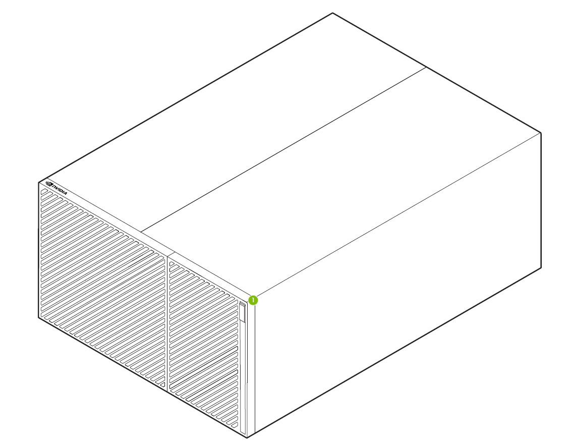
The following image shows the front view of the Developer Kit.

The labels in the image correspond to the following:
Power button
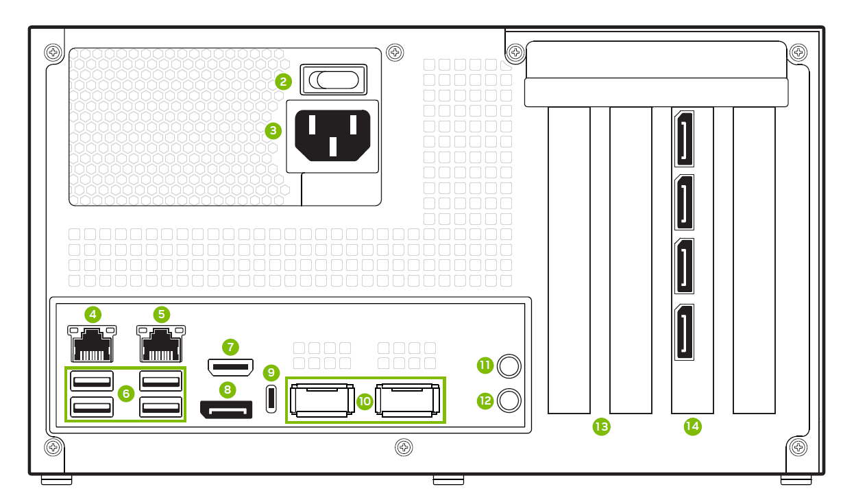
The following image shows the back view of the Developer Kit.

The labels in the image correspond to the following:
Power switch
Power cable connection
1GbE RJ45 with connection to the Orin CCPLEX
1GbE RJ45 with connection to the Orin CCPLEX and BMC
(4x) USB 3.2 Gen2 Type A
HDMI-Input
DisplayPort output from the Orin module.
USB 3.2 Gen2 Type C connector
(2x) QSFP28 ports (up to 100GbE per port)
Line-Out
MIC
PCIe Gen5 single width slots (x8 connected). See Install Additional Cards for steps to remove the cover and access slot 13.
PCIe Gen5 double width slot (x16 connected). The (4x) DisplayPorts depicted in the diagram are present only when the optional NVIDIA RTX A6000 was ordered from a distributor.
Install Additional Cards#
Observe the following precautions:
Only connect or disconnect a PCIe card (e.g., miniSAS or dGPU) when the system is powered down.
Apply extra care when plugging and removing PCIe cards to avoid stress, such as wearing, bending, or breaking, on the PCIe connectors.
Follow these instructions to install additional PCIe cards:
Remove the cover as shown in the following image. Remove the three screws on the right side when facing the back panel.
Remove the cover in the direction of A and B, as shown in the following image. The movement in the direction of A should be around 0.5 inch, or less than 1.5 cm.
After the cover is removed, remove the screws on top of slot 13 before installing the card in the PCIe slot-13. You can now access the IO of the PCIe card from the developer kit back panel.
Note
NVIDIA IGX Orin Developer Kit dGPU Installation Guidelines (DA-11330-001) on the NVIDIA Product information database describes the chassis panel removal process in detail.

