LidarHistogramConversion#
Overview#
The LidarHistogramConversion operator turns per-pixel LiDAR histogram data into optional range, Cartesian XYZ, and reflectance outputs. Each spatial location may carry one or more histograms; each histogram is a sequence of time-bin counts with optional opaque sensor headers.
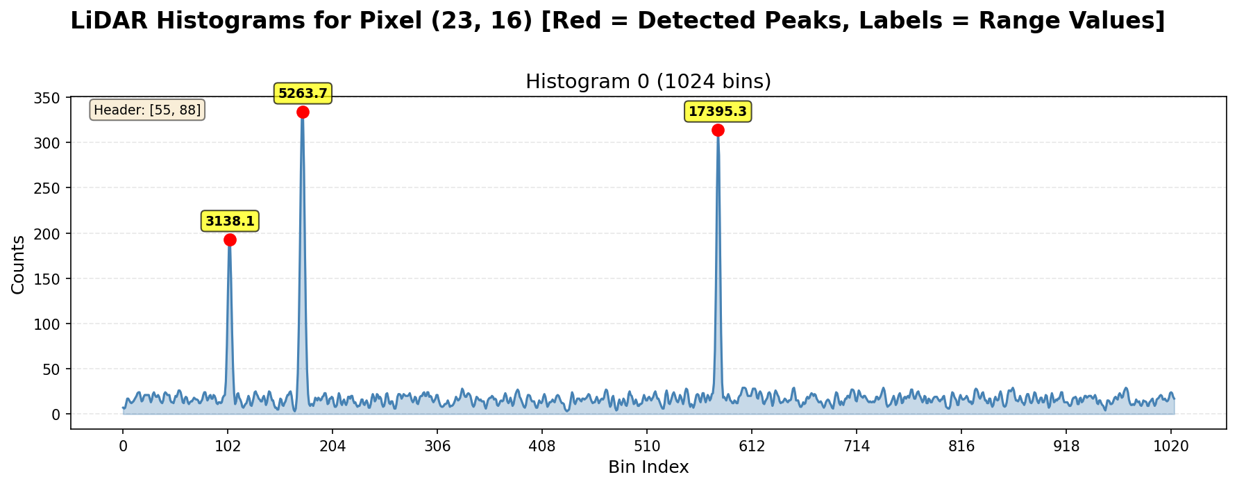
Figure 1: Example of a LiDAR histogram with detected peaks#
Processing follows unpack, per-histogram smoothing, peak detection, sub-bin time-of-flight refinement, and optional calibration steps to produce the requested outputs.
Algorithm Description#
Pixel layout#
A pixel is the full C-channel payload at one (H, W) index. Its logical layout is:
[pixelHeader] histogram_0 ... histogram_{N-1}
where N = numHistPerPixel. Each histogram has:
[histHeader] bin_0 ... bin_{K-1}
where K = numBinsPerHist. Pixel and histogram headers are treated as opaque sensor metadata at the API boundary; the
stages below use the bin counts only.
Two packing modes are supported:
NONE: histogram and header samples are logically 16-bit elements in the input tensor.
RAW12: pairs of 12-bit samples are packed as 24 bits (3 bytes) per pair. When this mode is used,
pixelHeaderSize,histHeaderSize, andnumBinsPerHistmust be even.
Unpacking (conceptual)#
Packed input is decoded into per-histogram bin arrays. Before smoothing, each histogram is extended at both ends with symmetric (reflective) padding so a fixed-width smoothing filter has well-defined boundary conditions.
Smoothing#
Each histogram is smoothed in place with a fixed 7-tap Gaussian kernel (sigma = 1.0, normalized coefficients
[0.0044, 0.054, 0.242, 0.399, 0.242, 0.054, 0.0044]).
Peak detection#
Before scanning for peaks, a noise floor threshold is derived from the smoothed histogram to gate candidate evaluation. The threshold is:
where \(H_{\min}\) and \(H_{\max}\) are the minimum and maximum values of the smoothed histogram. The \(\tfrac{1}{8}\) margin is chosen as a conservative SNR gate: it sits comfortably above the noise floor (which clusters near \(H_{\min}\)) while remaining well below any genuine return, and is hard-coded into the algorithm. A bin must satisfy \(v > \theta\) before it is considered as a peak candidate.
Peaks are found with 3-bin non-maximum suppression on the smoothed histogram: an interior bin is a candidate maximum if its value is strictly greater than both neighbors. Plateaus (flat tops) are treated as a single peak whose index is the mean of the plateau span. The operator keeps the top ``numPeaksPerHist`` peaks by descending value; ties favor the smaller bin index.
Range (time-of-flight to distance)#
For each accepted peak at integer bin index \(k\), sub-bin refinement uses parabolic interpolation on the three samples \(y_{k-1}, y_k, y_{k+1}\) (end samples are replicated when \(k\) is at the boundary):
with \(\delta\) clamped to \([-\tfrac{1}{2}, \tfrac{1}{2}]\) when the denominator is numerically well conditioned. The sub-bin index is \(\tilde{k} = k + \delta\) (clamped below at 0). Time-of-flight in nanoseconds is:
Let \(c\) denote the speed of light in meters per nanosecond. Range for peak \(p\) is:
where rangeBias is a per-pixel calibration value. If no peak is present in a slot (index -1), the corresponding
range is 0.
XYZ coordinates#
When XYZ output is requested, each peak range is multiplied by three per-pixel calibration coefficients \((c_x, c_y, c_z)\):
The host API requires xyzCalibration whenever XYZ is produced, and range bias must be provided if XYZ calibration
is used (XYZ is derived from calibrated range).
Reflectance#
Reflectance estimates signal strength as the sum of the three bins centered on each peak in the smoothed histogram (partial windows at the edges use only in-range bins). The output is:
when maxIntensity > 0, else 0. Values are not clamped to [0, 1]: intensities above maxIntensity yield
reflectance greater than 1. Missing peaks produce 0.
Implementation Details#
Histogram specification and runtime parameters#
PvaLidarHistogramSpec describes how to interpret the input C dimension: packingType, numHistPerPixel (1–8),
numBinsPerHist (3–2048), numPeaksPerHist (1–8), pixelHeaderSize (0–64), and histHeaderSize (0–16).
PvaLidarHistogramParams supplies offsetNs, binSizeNs, rangeScale, and maxIntensity. Full tensor
layout, dtype, and optionality rules for submit are documented in OpLidarHistogramConversion.h.
Dataflow configuration#
TensorDataFlow (TDF) brings histogram tiles from DRAM into a double-buffered VMEM input region sized for the worst-case pixel/histogram layout (utilizing one whole superbank). To support a wide variety of input tensor shapes, the DMA maps one full pixel (histogram tensor C dim) as the TDF width, tensor width as the TDF height, and tensor height as the TDF depth. Tile size is selected to pull in as many pixels in the tensor width dimension as possible, and for simplicity keeps a fixed tile “depth” of 1. More efficient use of VMEM may be possible if the input tensor shape is known apriori by pulling an exact multiple of pixels in the tensor width dimension and modifying the code to support a tile “depth” > 1.
SequenceDataFlow (SQDF) optionally streams per-pixel range bias and XYZ calibration from DRAM into VMEM before range/XYZ stages.
A single SQDF output path multiplexes optional range, XYZ, and reflectance DMAs. Reflectance is computed after range has been written out when both are enabled, because reflectance reuses the same intermediate VMEM buffer as range.
Tile traversal follows the TensorDataFlow order depth → width → height, which corresponds to the histogram tensor’s H,
C, and W dimensions respectively. The resulting pattern is a “strip-mining” type of traversal, where the first
tile contains the first numHistPixPerTile pixels from row 0, the next tile contains numHistPixPerTile pixels from
row 1, etc., then the next numHistPixPerTile column of tiles is visited from row 0, etc.
VMEM buffer allocation (conceptual)#
The main kernel uses dedicated VMEM regions for: double-buffered packed histogram input; unpacked pixel and histogram headers; padded uint16 histogram working storage (including halo, pitch-aigned to vector width, and a space for one pixel of RAW12 decode scratch); peak index/value staging; float range/reflectance staging (reused buffer); float XYZ staging; and optional per-tile range bias and XYZ calibration inputs.
Kernel workflow#
For each histogram tile:
Unpack pixel headers, histogram headers, and bins (NONE or RAW12 path); release the input tile early when done.
Optionally, start the DMA of range-bias and XYZ calibration tiles.
For every histogram: smooth, then detect peaks.
If range or XYZ is enabled: sync the calibration data DMA, then for each histogram peak, compute range and XYZ.
DMA range and/or XYZ outputs (if requested).
If reflectance is enabled: overwrite the shared staging buffer with reflectance, then DMA it out.
Unpacking#
The VPU kernel separates pixel headers, histogram headers, and bin arrays into distinct VMEM regions. That
split keeps header metadata out of the convolution path, matches alignment needs for vector loads (including RAW12), and
leaves room for future use of header fields. Histogram bins are stored in a vector-width-aligned working buffer:
each histogram includes a fixed halo of 3 bins, then numBinsPerHist samples, then 3 trailing bins for halo,
then the next histogram starts aligned to the next vector width.
NONE packing: headers and bins are simply copied with double-vector bulk moves from the acquired tile to the respective buffers.
RAW12 packing: the kernel requires 4-byte alignment of the tile base pointer and expects the per-pixel byte stride to be a multiple of 3 bytes (every pixel contains an integral number of RAW12 pairs). Decoding uses WX-style 24-bit vector loads to pick up a pair of 12-bit samples per lane directly from VMEM into a vshortx vector register. Each RAW12 pixel pair (A,B) is packed as A[4:11]B[4:11]B[0:3]A[0:3] from least to most significant bits. The vector code performs bitwise operations to extract the 12-bit samples, zero-extend to 16-bits, and store to the appropriate header and bin buffers while being careful to put the samples in the correct order. The offset into the input buffer is adjusted to maintain both the 4 and 3-byte alignment requirements when loading vectors of RAW12 samples.
Reflective halo fill: after bins are extracted to the histogram buffer, the three leading and three trailing halo bins are reflected using permutation patterns to initialize the boundary conditions for the smoothing kernel.
Smoothing#
Smoothing runs in place on the uint16 bins using floating-point accumulators. The 7 taps are applied with an
agen-driven sliding window: seven consecutive short vectors are widened to dvfloatx, multiplied by fixed
coefficients, summed, rounded, and narrowed back to uint16 for each output vector. The loop is structured so the
next iteration’s leading taps are loaded before overwriting overlapping memory. Vector width and the precomputed pitch
ensure the reflection-based halo scheme remains valid (the kernel asserts the vector width exceeds the kernel radius).
The smoothing pass also collects the minimum and maximum of the smoothed bins at no additional cost by enabling the
Thor VPU AGEN’s built-in min/max tracking feature (minmax_opt = 3 for unsigned tracking). When this mode is active,
the hardware updates running min and max accumulators in the store pipeline on every vector write; the values are readable
from the AGEN register after the loop completes. Because the smoothing result is written through this same output AGEN,
\(H_{\min}\) and \(H_{\max}\) are ready for the noise floor threshold calculation immediately after smoothing
returns, with no extra pass over the histogram data. The final store in the smoothing loop uses a per-lane predicated
store to restrict tracking to the valid bins only, avoiding contamination of \(H_{\min}\) from the padding lanes
written in the last partial vector when numBinsPerHist is not a multiple of the vector width.
Peak detection#
The noise floor threshold \(\theta\) is computed from \(H_{\min}\) and \(H_{\max}\) returned by the smoothing pass (see above) and passed into the peak detection routine as its initial minimum-peak-value gate. The peak value output array is pre-filled with \(\theta\) so that the gate remains active throughout the scan even before the top-N list is fully populated.
Peak detection is vectorized over the histogram width in chunks of ``vushort``. For each chunk, left, center, and right neighbor vectors are compared to form rising and falling edges; ``vcollate_idx_bits`` compacts edge indices for scalar follow-up. Plateaus that span chunk boundaries use a carry-over scalar state so a rising edge without a matching falling edge in the current chunk can pair with a falling edge in the next. The top N peaks are maintained in VMEM as two short vectors (indices and values) with an insertion shuffle by descending value.
To keep the final vector comparison well defined, the implementation writes one extra zero immediately after the last
valid bin (histogram[numBins] = 0) so a one-lane over-read at the end of the scan does not pick up garbage. A lane
mask suppresses partial lanes in the last chunk when numBinsPerHist is not a multiple of the vector width.
Range, XYZ, and reflectance#
Sub-bin interpolation, bias, scaling, XYZ scaling, and the three-bin intensity sum for reflectance are implemented in
scalar-style loops over peaks (numPeaksPerHist is small relative to typical vector widths). When both range and
reflectance outputs are enabled, reflectance overwrites the same VMEM buffer used to stage range after range has been
transferred out via DMA, so output ordering is enforced in the main tile loop.
Performance#
Performance numbers for this operator are not yet published and will be added in a future release.