Radar Processing Pipeline (4T4R)#
Overview#
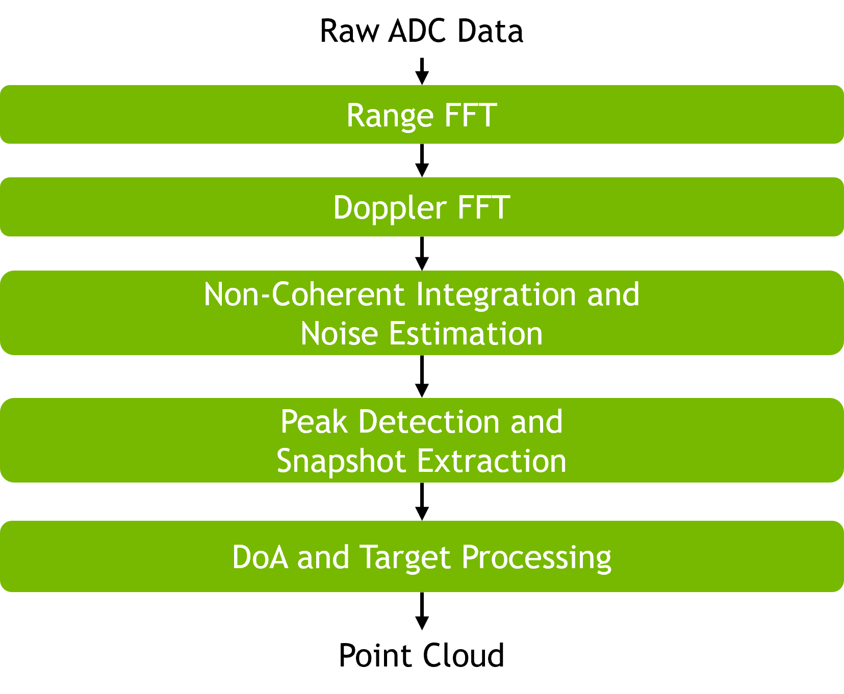
The 4T4R radar PVA pipeline processes raw ADC samples from a 4 TX × 4 RX MIMO radar and produces a point cloud of detected targets in both polar (range, radial velocity, azimuth, elevation) and Cartesian (X, Y, Z) coordinates. The radar is an FMCW sensor with DDMA (Doppler-Division Multiple Access) waveform modulation across the 4 TX channels — each TX transmits with a unique Doppler offset within the coherent processing interval so the TX signals stay separable on the receive side, and the per-TX offsets are used later to unfold each detection across its Doppler aliases. The pipeline is organized as a 5-stage flow of PVA operators: Range FFT → Doppler FFT → NCI (with Noise Estimation) → Peak Detection (with Snapshot Extraction) → DOA (with Target Processing). Compared to the 8T8R pipeline, the 4T4R pipeline combines peak detection + snapshot extraction into a single stage and fuses DOA + target processing into a single stage using the phase-compensated dual-aperture FFT (DA-FFT) algorithm.
|
Input Data#
The 4T4R pipeline is driven by fixed-point ADC captures recorded from a 4 TX × 4 RX MIMO radar sensor. Capture files are placed in the radar/4t4r/ assets subdirectory (file prefix data_) and read frame-by-frame by the pipeline sample application.
Each frame is a [numChirps][numRx][numSamples] real-valued ADC cube that is fed directly into the pipeline as the Step 1 input.
Usage#
The pipeline is exposed as a C++ abstract interface, IRadarPipeline, declared in radar_pipeline_iface.hpp and implemented by the radar_pipeline_4t4r library. Applications link the library directly and obtain an instance via the factory function:
#include "radar_pipeline_iface.hpp"
std::unique_ptr<IRadarPipeline> pipeline{ radar_pipeline_4t4r() };
Key methods on IRadarPipeline:
init()— configure the pipeline from aRadarPipelineConfigand allocate PVA resources.process()— run all five stages on one frame; zero-copy on PVA device pointers.get_target_count()— number of targets in the most recent frame.validate()— run the CPU reference pipeline and compare stage-by-stage.
The radar_pipeline sample executable links against both 4T4R and 8T8R variants and selects one at runtime via --antenna_config:
./radar_pipeline $PIPELINE_ASSETS --antenna_config 4t4r
Pipeline Stages#
All stages execute on PVA. Stages 1, 2, and 4 are fully fixed-point; Stage 3 (NCI) uses floating-point math internally (magnitude computation) but produces fixed-point results; Stage 5 (DOA + Target Processing) produces floating-point results. Complex fixed-point tensors use Q11.20 format over signed int32 (SQ11.20). The output Cartesian coordinates follow the automotive convention: X = lateral, Y = forward (along the vehicle heading), Z = vertical (up).
Top-level I/O
Direction |
Tensor |
Shape / dtype |
|---|---|---|
Input |
ADC Data |
|
Input |
Configuration |
|
Output |
Target List |
|
Step 1 — Range FFT#
Converts the fast-time (intra-chirp) ADC samples to the range-frequency domain via a windowed FFT per RX channel and chirp. See Range FFT for the operator implementation.
Direction |
Tensor |
Shape / dtype |
|---|---|---|
Input |
ADC Data |
|
Output |
Range Profile |
|
Step 2 — Doppler FFT#
Extracts target velocity information by running an FFT across the slow-time (chirp) axis for each range bin and RX channel, with the output transposed so that the range axis becomes the outermost dimension. This layout matches the NCI stage’s memory-access pattern for the 4T4R configuration. See Doppler FFT for the operator implementation.
Direction |
Tensor |
Shape / dtype |
|---|---|---|
Input |
Range Profile |
|
Output |
Range-Doppler Map |
|
Step 3 — NCI (Non-Coherent Integration) with Noise Estimation#
Accumulates magnitude energy across RX channels (nciRx) and then across Doppler folds (nciFinal) to improve detection SNR, and estimates a range-dependent noise floor (noiseEstimate) used by the downstream threshold-based peak detector. The noise floor per range bin is derived from the minimum of the folded NCI over the Doppler axis, scaled by a fixed threshold factor. See NCI for the operator implementation.
Direction |
Tensor |
Shape / dtype |
|---|---|---|
Input |
Range-Doppler Map |
|
Input |
|
|
Output |
nciRx |
|
Output |
nciFinal |
|
Output |
noiseEstimate |
|
Step 4 — Peak Detection and Snapshot Extraction#
Detects local maxima in the folded NCI map using the range-dependent noise floor as a threshold, disambiguates each detection across Doppler folds, and gathers the 4×4 = 16-element complex virtual-aperture snapshot for each peak. See Peak Detection for the operator implementation.
Direction |
Tensor |
Shape / dtype |
|---|---|---|
Input |
Range-Doppler Map |
|
Input |
nciRx |
|
Input |
nciFinal |
|
Input |
noiseEstimate |
|
Output |
Peak Count |
|
Output |
Peak Indices |
|
Output |
Peak Snapshots |
|
Step 5 — DOA and Target Processing (DA-FFT, RV Decoupling, Cartesian Conversion)#
Estimates azimuth and elevation angles using the phase-compensated dual-aperture FFT (DA-FFT) algorithm specific to the 4T4R MIMO layout, then converts each target’s (range-bin, Doppler-bin, azimuth, elevation) to physical units — radial velocity, range, and Cartesian X/Y/Z — applying range-velocity decoupling. nciFinal is consumed by the quadratic interpolation step for sub-bin range refinement. See DA-FFT for the operator implementation.
Direction |
Tensor |
Shape / dtype |
|---|---|---|
Input |
Peak Count |
|
Input |
Calibration Vector |
|
Input |
Peak Indices |
|
Input |
Peak Snapshots |
|
Input |
nciFinal |
|
Output |
Target List |
|
Performance#
The performance of the radar pipeline is primarily determined by the size of the input tensor and the number of detected peaks.
Execution Time is the average time required to execute the operator on a single VPU core.
Note that each PVA contains two VPU cores, which can operate in parallel to process two streams simultaneously, or reduce execution time by approximately half by splitting the workload between the two cores.
Total Power represents the average total power consumed by the module when the operator is executed concurrently on both VPU cores.
Idle power is approximately 7W when the PVA is not processing data.
For detailed information on interpreting the performance table below and understanding the benchmarking setup, see Performance Benchmark.
SampleCount |
RxAntennaCount |
ChirpCount |
DataFile |
InputDataType |
OutputDataType |
DetectionCount |
Execution Time |
Submit Latency |
Total Power |
|---|---|---|---|---|---|---|---|---|---|
512 |
4 |
512 |
data_1 |
S32 |
F32 |
59 |
1.604ms |
0.239ms |
13.64W |