Radar Processing Pipeline (8T8R)#
Overview#
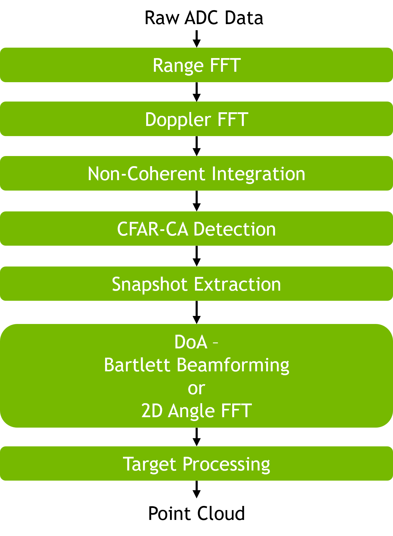
The 8T8R radar PVA pipeline processes raw ADC samples from an 8 TX × 8 RX MIMO radar and produces a point cloud of detected targets in both polar (range, radial velocity, azimuth, elevation) and Cartesian (X, Y, Z) coordinates. The radar is an FMCW sensor with DDMA (Doppler-Division Multiple Access) waveform modulation across the 8 TX channels — each TX transmits with a unique Doppler offset within the coherent processing interval so the TX signals stay separable on the receive side, and the per-TX offsets are used later by Snapshot Extraction to unfold each detection across its Doppler aliases. The pipeline is organized as a 7-stage flow of PVA operators: Range FFT → Doppler FFT → NCI → CFAR → Snapshot Extraction → DOA → Target Processing. Two interchangeable DOA variants are supported: Bartlett beamforming (azimuth and elevation with arbitrary antenna geometries via precomputed steering vectors) and a 2D Angle FFT (azimuth and elevation, fast, URA-only).
|
Input Data#
The pipeline is exercised end-to-end using synthetic ADC cubes produced by a MATLAB-based 4D MIMO radar simulator. The simulator produces baseband I/Q samples for a configurable scene, which are then quantized to the pipeline’s integer ADC format.
Each simulated frame is a [numChirps][numRx][numSamples] real-valued ADC cube that is fed directly into the pipeline as the Step 1 input.
Antenna Layout
The 8T8R configuration uses a simple uniform rectangular array (URA) layout: an 8-element TX array and an 8-element RX array arranged so that the resulting virtual aperture, after MIMO processing, is a 64-element URA with 0.5λ spacing in both azimuth and elevation.
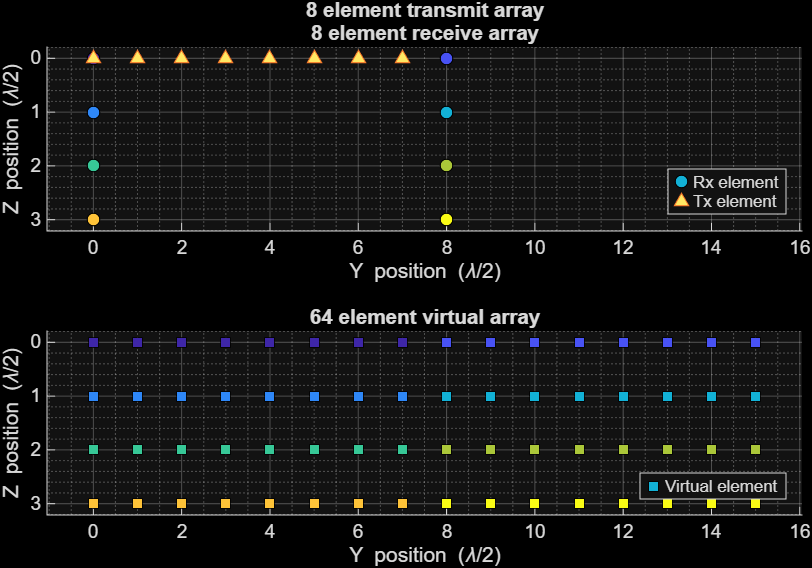
TX, RX, and resulting virtual-array element positions for the 8T8R sensor.#
Usage#
The pipeline is exposed as a C++ abstract interface, IRadarPipeline, declared in radar_pipeline_iface.hpp and implemented by the radar_pipeline_8t8r library. Applications link the library directly and obtain an instance via the factory function:
#include "radar_pipeline_iface.hpp"
std::unique_ptr<IRadarPipeline> pipeline{ radar_pipeline_8t8r() };
Key methods on IRadarPipeline:
init()— configure the pipeline from aRadarPipelineConfig(doa_params.doa_methodselects the DOA variant) and allocate PVA resources.process()— run all seven stages on one frame; zero-copy on PVA device pointers.get_target_count()— number of targets in the most recent frame.validate()— run the CPU reference pipeline and compare stage-by-stage.
The radar_pipeline sample executable links against both 4T4R and 8T8R variants and selects one at runtime via --antenna_config:
./radar_pipeline $PIPELINE_ASSETS --antenna_config 8t8r
Pipeline Stages#
All stages execute on PVA. Stages 1, 2, 4, and 5 are fully fixed-point; Stage 3 (NCI) uses floating-point math internally (magnitude computation) but produces fixed-point results; Stages 6 and 7 (DOA + Target Processing) produce floating-point results. Complex fixed-point tensors use Q11.20 format over signed int32 (SQ11.20). The output Cartesian coordinates follow the automotive convention: X = lateral, Y = forward (along the vehicle heading), Z = vertical (up).
Top-level I/O
Direction |
Tensor |
Shape / dtype |
|---|---|---|
Input |
ADC Data |
|
Input |
Configuration |
|
Output |
Target Count |
|
Output |
Target List |
|
Step 1 — Range FFT#
Converts the fast-time (intra-chirp) ADC samples to the range-frequency domain via a windowed FFT per RX channel and chirp. numRangeBins is configurable; the library default is numSamples / 2. See Range FFT for the operator implementation.
Direction |
Tensor |
Shape / dtype |
|---|---|---|
Input |
ADC Data |
|
Output |
Range Profile |
|
Step 2 — Doppler FFT#
Extracts target velocity information by running an FFT across the slow-time (chirp) axis for each range bin and RX channel. For 8T8R (numTx ≥ 8), the output is laid out as [numRangeBins][numDopplerBins][numRx] — the RX axis on the innermost (contiguous) dimension. This improves memory access throughput for the downstream snapshot-gathering stage, which reads numRx contiguous samples per detection to form the virtual-aperture snapshot. Other configurations use [numRangeBins][numRx][numDopplerBins]. See Doppler FFT for the operator implementation.
Direction |
Tensor |
Shape / dtype |
|---|---|---|
Input |
Range Profile |
|
Output |
Range-Doppler Map |
|
Step 3 — NCI (Non-Coherent Integration)#
Accumulates magnitude energy across RX channels (nciRx) and then across DDM Doppler folds (nciFinal) to improve detection SNR. See NCI for the operator implementation.
Direction |
Tensor |
Shape / dtype |
|---|---|---|
Input |
Range-Doppler Map |
|
Input |
|
|
Output |
nciRx |
|
Output |
nciFinal |
|
Step 4 — CFAR Detection#
Applies cell-averaging CFAR to the folded NCI map and produces a sparse list of (range, folded-Doppler) detections. See CFAR for the operator implementation.
Direction |
Tensor |
Shape / dtype |
|---|---|---|
Input |
nciFinal |
|
Output |
Detection Count |
|
Output |
Folded Detection List |
|
Step 5 — Snapshot Extraction (DDM Disambiguation + Gathering)#
Unfolds each CFAR detection back to the full Doppler axis using the per-TX DDM Doppler offsets, applies calibration weights, and gathers the 8×8 virtual-aperture complex snapshot needed by the DOA stage. See Snapshot Extraction for the operator implementation.
Direction |
Tensor |
Shape / dtype |
|---|---|---|
Input |
Detection Count |
|
Input |
Folded Detection List |
|
Input |
DDM Doppler Offsets |
|
Input |
nciRx |
|
Input |
Range-Doppler Map |
|
Input |
Calibration Weights |
|
Output |
Detection List |
|
Output |
Snapshots |
|
The figure below shows the detections on the NCI range-Doppler map after DDM disambiguation in this stage, i.e. with unfolded Doppler indices:
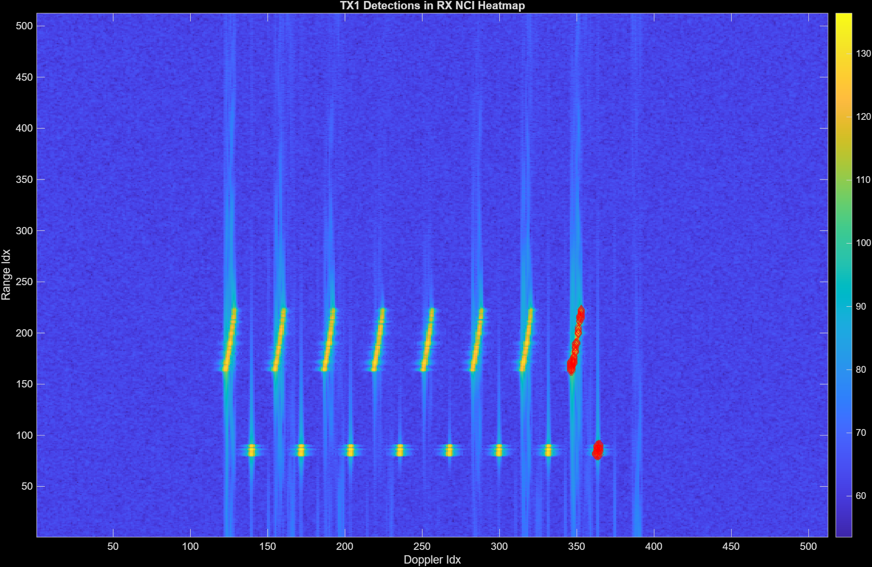
Detections overlaid on the NCI range-Doppler map after DDM disambiguation (unfolded Doppler indices).#
Step 6 — DOA Estimation#
DOA is selectable at pipeline creation time. Both variants consume the same snapshots and produce the same output tensor set, so downstream target processing is identical.
The Target Index Map is an output of this stage: targetIndexMap[t] holds the index of the detection (row in the Detection List) that produced target t. The mapping is one-to-one — one target per detection — so targetCount == detectionCount.
Variant A — Bartlett Beamforming
Conventional beamformer evaluated on a precomputed azimuth × elevation grid. Supports joint 2D angle estimation and arbitrary antenna geometries via external steering vectors. Two search modes are supported, selected at pipeline creation: a full 2D search that evaluates every (azimuth, elevation) pair in the grid, and a separable search that decomposes the 2D search into a 1D azimuth scan followed by a 1D elevation scan over a small neighborhood around the detected azimuth peak (see Bartlett Beamforming for the mode trade-offs and constraints).
Direction |
Tensor |
Shape / dtype |
|---|---|---|
Input |
Detection Count |
|
Input |
Snapshots |
|
Input |
Steering Vectors |
|
Input |
Azimuth Bins |
|
Input |
Elevation Bins |
|
Input |
Detection List |
|
Input |
DDM Doppler Offsets |
|
Output |
Target Count |
|
Output |
Target Index Map |
|
Output |
Target Angles |
|
Variant B — 2D Angle FFT
FFT-based angle estimation over the virtual aperture, factorized into numVirtualAzimuthElements × numVirtualElevationElements (product equals numTx × numRx). Produces both azimuth and elevation per target. Each detection snapshot is windowed and transformed with a 2D FFT (1D along azimuth, 1D along elevation); the peak of the resulting 2D power spectrum gives the coarse (azimuth, elevation) bin, and quadratic interpolation on a 3×3 neighborhood yields sub-bin resolution. This variant requires a uniform rectangular array with 0.5λ spacing on both axes, since FFT bin indices map directly to angles via θ = arcsin(normalized_index). See 2D Angle FFT for the operator implementation.
Direction |
Tensor |
Shape / dtype |
|---|---|---|
Input |
Detection Count |
|
Input |
Snapshots |
|
Input |
Detection List |
|
Input |
DDM Doppler Offsets |
|
Output |
Target Count |
|
Output |
Target Index Map |
|
Output |
Target Angles |
|
Step 7 — Target Processing (RV Decoupling + Cartesian Conversion)#
Converts each target’s (range-bin, Doppler-bin, azimuth, elevation) to physical units — radial velocity, range, and Cartesian X/Y/Z — applying range-velocity decoupling using the DDM Doppler offsets. nciFinal is consumed as a power/amplitude reference. See Target Processing for the operator implementation.
Direction |
Tensor |
Shape / dtype |
|---|---|---|
Input |
Target Count |
|
Input |
Detection Count |
|
Input |
Detection List |
|
Input |
Target Index Map |
|
Input |
Target Angles |
|
Input |
DDM Doppler Offsets |
|
Input |
nciFinal |
|
Output |
Target List |
|
Output Visualization#
The final per-frame output is a target list with Cartesian coordinates, suitable for rendering as a 3D point cloud. The figure below shows the point cloud produced by running the pipeline on a single MATLAB-simulated frame.
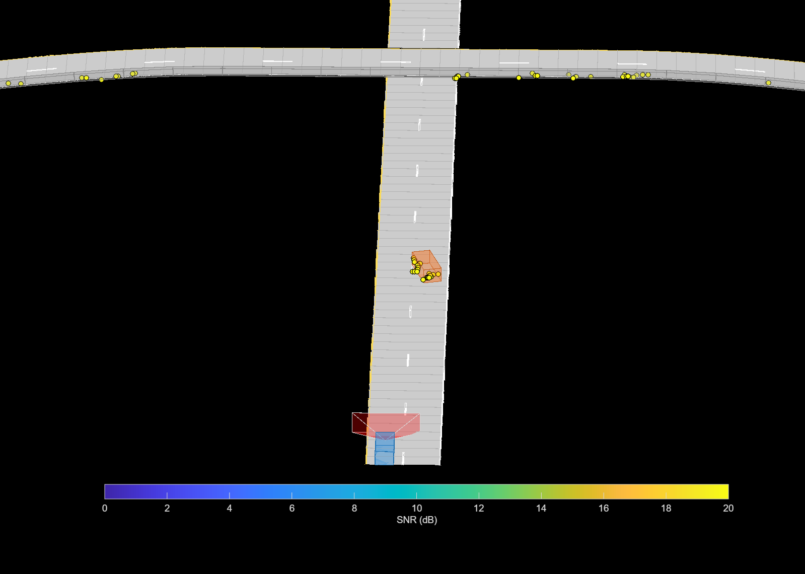
Point cloud from the 8T8R pipeline on a MATLAB-simulated scene.#
Performance#
The performance of the radar pipeline is primarily determined by the size of the input tensor, the number of CFAR detections, and the selected DOA method.
Execution Time is the average time required to execute the operator on a single VPU core.
Note that each PVA contains two VPU cores, which can operate in parallel to process two streams simultaneously, or reduce execution time by approximately half by splitting the workload between the two cores.
Total Power represents the average total power consumed by the module when the operator is executed concurrently on both VPU cores.
Idle power is approximately 7W when the PVA is not processing data.
For detailed information on interpreting the performance table below and understanding the benchmarking setup, see Performance Benchmark.
NumTx |
NumRx |
NumChirps |
NumSamples |
DoaMethod |
NumAzBins |
NumElevBins |
Layout |
PeakGrouping |
Separable |
DetectionCount |
Execution Time |
Submit Latency |
Total Power |
|---|---|---|---|---|---|---|---|---|---|---|---|---|---|
4 |
4 |
512 |
512 |
Bartlett |
81 |
8 |
RangeRxDoppler |
0 |
0 |
435 |
5.392ms |
0.218ms |
11.801W |
4 |
4 |
512 |
512 |
Bartlett |
81 |
8 |
RangeRxDoppler |
0 |
1 |
435 |
3.646ms |
0.144ms |
12.402W |
4 |
4 |
512 |
512 |
Bartlett |
81 |
8 |
RangeRxDoppler |
1 |
0 |
41 |
2.129ms |
0.214ms |
13.949W |
4 |
4 |
512 |
512 |
Bartlett |
81 |
8 |
RangeRxDoppler |
1 |
1 |
41 |
1.958ms |
0.143ms |
14.15W |
4 |
4 |
512 |
512 |
Bartlett |
161 |
51 |
RangeRxDoppler |
0 |
1 |
435 |
4.709ms |
0.144ms |
12.302W |
4 |
4 |
512 |
512 |
Bartlett |
161 |
51 |
RangeRxDoppler |
1 |
1 |
41 |
2.069ms |
0.143ms |
14.049W |
4 |
4 |
512 |
1024 |
Bartlett |
81 |
8 |
RangeRxDoppler |
0 |
0 |
436 |
6.737ms |
0.216ms |
12.864W |
4 |
4 |
512 |
1024 |
Bartlett |
81 |
8 |
RangeRxDoppler |
0 |
1 |
436 |
4.911ms |
0.142ms |
13.368W |
4 |
4 |
512 |
1024 |
Bartlett |
81 |
8 |
RangeRxDoppler |
1 |
0 |
41 |
3.497ms |
0.216ms |
14.532W |
4 |
4 |
512 |
1024 |
Bartlett |
81 |
8 |
RangeRxDoppler |
1 |
1 |
41 |
3.242ms |
0.141ms |
15.015W |
4 |
4 |
512 |
1024 |
Bartlett |
161 |
51 |
RangeRxDoppler |
0 |
1 |
436 |
5.974ms |
0.142ms |
12.885W |
4 |
4 |
512 |
1024 |
Bartlett |
161 |
51 |
RangeRxDoppler |
1 |
1 |
41 |
3.353ms |
0.142ms |
14.633W |
8 |
8 |
512 |
512 |
AngleFFT |
0 |
0 |
RangeRxDoppler |
0 |
0 |
222 |
3.785ms |
0.124ms |
14.15W |
8 |
8 |
512 |
512 |
AngleFFT |
0 |
0 |
RangeRxDoppler |
1 |
0 |
20 |
2.991ms |
0.125ms |
15.116W |
8 |
8 |
512 |
512 |
AngleFFT |
0 |
0 |
RangeDopplerRx |
0 |
0 |
222 |
3.845ms |
0.130ms |
14.331W |
8 |
8 |
512 |
512 |
AngleFFT |
0 |
0 |
RangeDopplerRx |
1 |
0 |
20 |
3.247ms |
0.129ms |
15.015W |
8 |
8 |
512 |
512 |
Bartlett |
81 |
8 |
RangeRxDoppler |
0 |
0 |
222 |
8.010ms |
0.209ms |
12.763W |
8 |
8 |
512 |
512 |
Bartlett |
81 |
8 |
RangeRxDoppler |
0 |
1 |
222 |
4.875ms |
0.136ms |
14.049W |
8 |
8 |
512 |
512 |
Bartlett |
81 |
8 |
RangeRxDoppler |
1 |
0 |
20 |
3.560ms |
0.207ms |
14.431W |
8 |
8 |
512 |
512 |
Bartlett |
81 |
8 |
RangeRxDoppler |
1 |
1 |
20 |
3.217ms |
0.134ms |
14.914W |
8 |
8 |
512 |
512 |
Bartlett |
81 |
8 |
RangeDopplerRx |
0 |
0 |
222 |
8.043ms |
0.217ms |
12.662W |
8 |
8 |
512 |
512 |
Bartlett |
81 |
8 |
RangeDopplerRx |
0 |
1 |
222 |
4.936ms |
0.143ms |
13.851W |
8 |
8 |
512 |
512 |
Bartlett |
81 |
8 |
RangeDopplerRx |
1 |
0 |
20 |
3.788ms |
0.215ms |
14.431W |
8 |
8 |
512 |
512 |
Bartlett |
81 |
8 |
RangeDopplerRx |
1 |
1 |
20 |
3.471ms |
0.140ms |
14.532W |
8 |
8 |
512 |
512 |
Bartlett |
161 |
51 |
RangeRxDoppler |
0 |
1 |
222 |
6.804ms |
0.136ms |
13.368W |
8 |
8 |
512 |
512 |
Bartlett |
161 |
51 |
RangeRxDoppler |
1 |
1 |
20 |
3.420ms |
0.136ms |
15.015W |
8 |
8 |
512 |
512 |
Bartlett |
161 |
51 |
RangeDopplerRx |
0 |
1 |
222 |
6.860ms |
0.142ms |
13.267W |
8 |
8 |
512 |
512 |
Bartlett |
161 |
51 |
RangeDopplerRx |
1 |
1 |
20 |
3.676ms |
0.140ms |
14.431W |
8 |
8 |
512 |
1024 |
AngleFFT |
0 |
0 |
RangeRxDoppler |
0 |
0 |
223 |
6.118ms |
0.126ms |
14.532W |
8 |
8 |
512 |
1024 |
AngleFFT |
0 |
0 |
RangeRxDoppler |
1 |
0 |
20 |
5.329ms |
0.126ms |
15.493W |
8 |
8 |
512 |
1024 |
AngleFFT |
0 |
0 |
RangeDopplerRx |
0 |
0 |
223 |
6.490ms |
0.132ms |
14.431W |
8 |
8 |
512 |
1024 |
AngleFFT |
0 |
0 |
RangeDopplerRx |
1 |
0 |
20 |
5.900ms |
0.130ms |
15.694W |
8 |
8 |
512 |
1024 |
Bartlett |
81 |
8 |
RangeRxDoppler |
0 |
0 |
223 |
10.419ms |
0.211ms |
13.066W |
8 |
8 |
512 |
1024 |
Bartlett |
81 |
8 |
RangeRxDoppler |
0 |
1 |
223 |
7.219ms |
0.135ms |
14.049W |
8 |
8 |
512 |
1024 |
Bartlett |
81 |
8 |
RangeRxDoppler |
1 |
0 |
20 |
5.955ms |
0.211ms |
14.532W |
8 |
8 |
512 |
1024 |
Bartlett |
81 |
8 |
RangeRxDoppler |
1 |
1 |
20 |
5.558ms |
0.136ms |
15.015W |
8 |
8 |
512 |
1024 |
Bartlett |
81 |
8 |
RangeDopplerRx |
0 |
0 |
223 |
10.775ms |
0.216ms |
12.965W |
8 |
8 |
512 |
1024 |
Bartlett |
81 |
8 |
RangeDopplerRx |
0 |
1 |
223 |
7.590ms |
0.141ms |
14.331W |
8 |
8 |
512 |
1024 |
Bartlett |
81 |
8 |
RangeDopplerRx |
1 |
0 |
20 |
6.510ms |
0.216ms |
14.431W |
8 |
8 |
512 |
1024 |
Bartlett |
81 |
8 |
RangeDopplerRx |
1 |
1 |
20 |
6.121ms |
0.141ms |
14.532W |
8 |
8 |
512 |
1024 |
Bartlett |
161 |
51 |
RangeRxDoppler |
0 |
1 |
223 |
9.153ms |
0.136ms |
13.848W |
8 |
8 |
512 |
1024 |
Bartlett |
161 |
51 |
RangeRxDoppler |
1 |
1 |
20 |
5.761ms |
0.137ms |
14.633W |
8 |
8 |
512 |
1024 |
Bartlett |
161 |
51 |
RangeDopplerRx |
0 |
1 |
223 |
9.526ms |
0.143ms |
13.848W |
8 |
8 |
512 |
1024 |
Bartlett |
161 |
51 |
RangeDopplerRx |
1 |
1 |
20 |
6.328ms |
0.142ms |
14.532W |