Switching Support
NVIDIA DOCA Switching Support
This document provides information on the control of the NVIDIA® BlueField® DPU embedded switch and representation of the host network functions.
This model is only applicable when the DPU is operating ECPF ownership mode.
BlueField uses netdev representors to map each one of the host side physical and virtual functions:
- Serve as the tunnel to pass traffic for the virtual switch or application running on the Arm cores to the relevant physical function (PF) or virtual function (VF) on the host side.
- Serve as the channel to configure the embedded switch with rules to the corresponding represented function.
Those representors are used as the virtual ports being connected to OVS or any other virtual switch running on the Arm cores.
When operating in DPU mode , we see 2 representors for each one of the DPU's network ports: one for the uplink, and another one for the host side PF (the PF representor created even if the PF is not probed on the host side). For each one of the VFs created on the host side a corresponding representor would be created on the Arm side. The naming convention for the representors is as follows:
-
Uplink representors: p<port_number>
-
PF representors: pf<port_number>hpf
-
VF representors: pf<port_number>vf<function_number>
The following diagram shows the mapping of between the PCIe functions exposed on the host side and the representors. For the sake of simplicity, a single port model (duplicated for the second port) is shown.
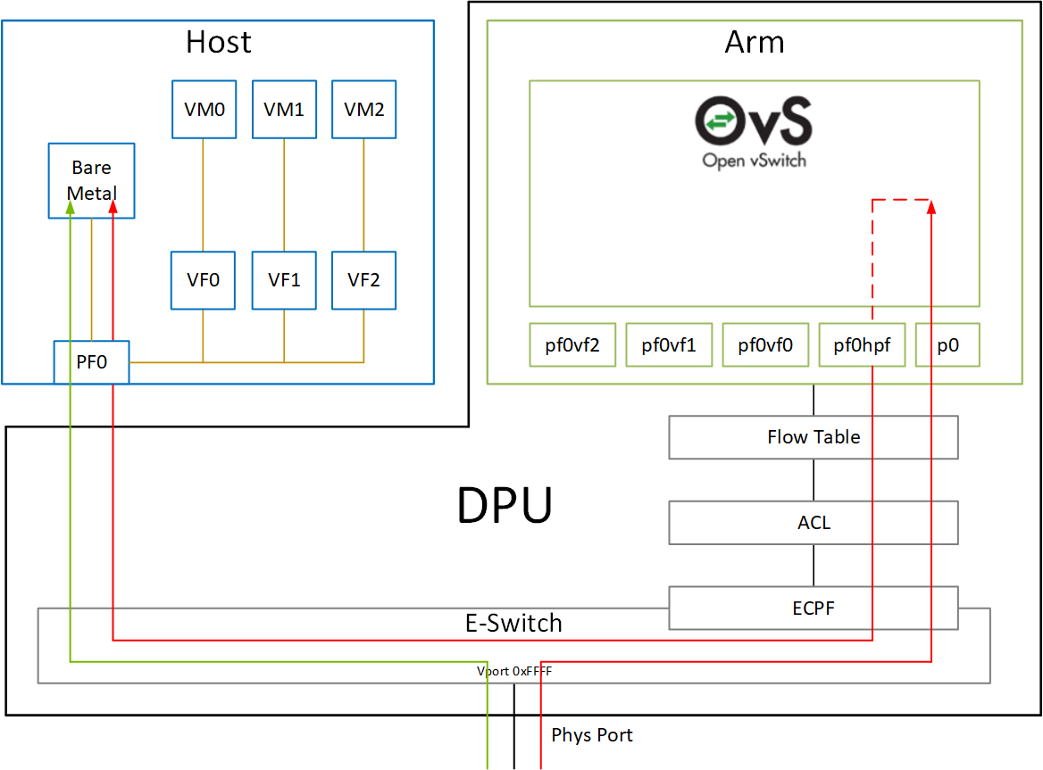
The red arrow demonstrates a packet flow through the representors, while the green arrow demonstrates the packet flow when steering rules are offloaded to the embedded switch. More details on that are available in the switch offload section.
The following is a functional diagram of the BlueField DPU.
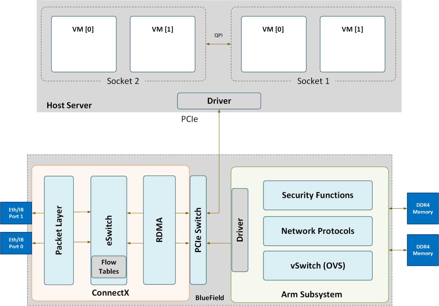
For each BlueField DPU network port, there are 2 physical PCIe networking functions exposed:
- To the embedded Arm subsystem
- To the host over PCIe
Different functions have different default grace period values during which functions can recover from/handle a single fatal error:
- ECPFs have a graceful period of 3 minutes
- PFs have a graceful period of 1 minute
- VFs/SFs have a graceful period of 30 seconds
The mlx5 drivers and their corresponding software stacks must be loaded on both hosts (Arm and the host server). The OS running on each one of the hosts would probe the drivers. BlueField-2 network interfaces are compatible with NVIDIA® ConnectX®-6 Dx and higher. BlueField-3 network interfaces are compatible with ConnectX-7 and higher.
The same network drivers are used both for BlueField and the ConnectX family of products.
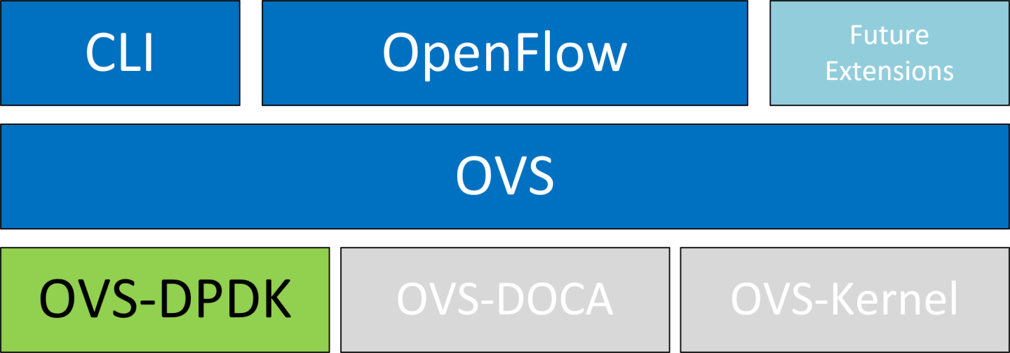
Open vSwitch (OVS) is a software-based network technology that enhances virtual machine (VM) communication within internal and external networks. Typically deployed in the hypervisor, OVS employs a software-based approach for packet switching, which can strain CPU resources, impacting system performance and network bandwidth utilization. Addressing this, NVIDIA's Accelerated Switching and Packet Processing (ASAP2) technology offloads OVS data-plane tasks to specialized hardware, like the embedded switch (eSwitch) within the NIC subsystem, while maintaining an unmodified OVS control-plane. This results in notably improved OVS performance without burdening the CPU.
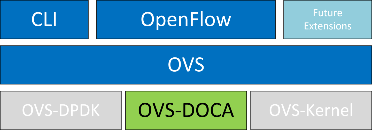
NVIDIA's OVS architecture extends the traditional OVS-DPDK and OVS-Kernel data-path offload interfaces, introducing OVS-DOCA as an additional implementation. OVS-DOCA, built upon NVIDIA's networking API, preserves the same interfaces as OVS-DPDK and OVS-Kernel while utilizing the DOCA Flow library. Unlike the other modes, OVS-DOCA exploits unique hardware offload mechanisms and application techniques, maximizing performance and features for NVIDA NICs and DPUs. This mode is especially efficient due to its architecture and DOCA library integration, enhancing e-switch configuration and accelerating hardware offloads beyond what the other modes can achieve.
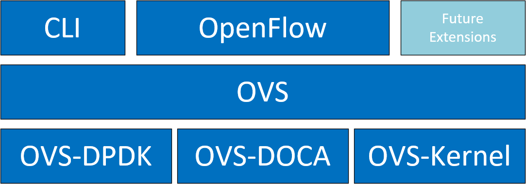
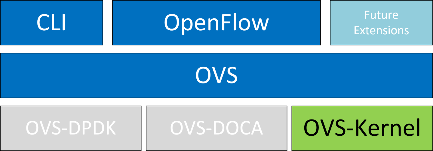
NVIDIA OVS installation contains all three OVS flavors. The following subsections describe the three flavors (default is OVS-Kernel) and how to configure each of them.
OVS and Virtualized Devices
When OVS is combined with NICs and DPUs (such as NVIDIA® ConnectX®-6 Lx/Dx and NVIDIA® BlueField®-2 and later), it utilizes the hardware data plane of ASAP2. This data plane can establish connections to VMs using either SR-IOV virtual functions (VFs) or virtual host data path acceleration (vDPA) with virtio.
In both scenarios, an accelerator engine within the NIC accelerates forwarding and offloads the OVS rules. This integrated solution accelerates both the infrastructure (via VFs through SR-IOV or virtio) and the data plane. For DPUs (which include a NIC subsystem), an alternate virtualization technology implements full virtio emulation within the DPU, enabling the host server to communicate with the DPU as a software virtio device.
- When using ASAP2 data plane over SR-IOV virtual functions (VFs), the VF is directly passed through to the VM, with the NVIDIA driver running within the VM.
- When using vDPA, the vDPA driver allows VMs to establish their connections through VirtIO. As a result, the data plane is established between the SR-IOV VF and the standard virtio driver within the VM, while the control plane is managed on the host by the vDPA application.
Note:
Two flavors of vDPA are supported, Software vDPA; and Hardware vDPA. Software vDPA management functionality is embedded into OVS-DPDK, while Hardware vDPA uses a standalone application for management, and can be run with both OVS-Kernel and OVS-DPDK. For further information, see sections VirtIO Acceleration Through VF Relay: Software and Hardware vDPA and VirtIO Acceleration Through Hardware vDPA.
4.1. OVS Hardware Offloads Configuration
4.1.1. OVS-Kernel Hardware Offloads
OVS-Kernel is the default OVS flavor enabled on your NVIDIA device.
4.1.1.1. Switchdev Configuration
- Unbind the VFs:
            echo 0000:04:00.2 > /sys/bus/pci/drivers/mlx5_core/unbind
echo 0000:04:00.3 > /sys/bus/pci/drivers/mlx5_core/unbind
- Change the eSwitch mode from legacy to switchdev on the PF device:
# devlink dev eswitch set pci/0000:3b:00.0 mode switchdev
Note:
On OSes or kernels that do not support devlink, moving to switchdev mode can be done using sysfs:# echo switchdev > /sys/class/net/enp4s0f0/compat/devlink/mode
- At this stage, VF representors have been created. To map a representor to its VF, make sure to obtain the representor's
switchidandportnameby running:# ip -d link show eth4 41: enp0s8f0_1: <BROADCAST,MULTICAST,UP,LOWER_UP> mtu 1500 qdisc mq state UP mode DEFAULT group default qlen 1000 link/ether ba:e6:21:37:bc:d4 brd ff:ff:ff:ff:ff:ff promiscuity 0 addrgenmode eui64 numtxqueues 10 numrxqueues 10 gso_max_size 65536 gso_max_segs 65535 portname pf0vf1 switchid f4ab580003a1420c
-
switchid– used to map representor to device, both device PFs have the sameswitchid -
portname– used to map representor to PF and VF. Value returned ispf<X>vf<Y>, whereXis the PF number andYis the number of VF.
-
- Bind the VFs:
            echo 0000:04:00.2 > /sys/bus/pci/drivers/mlx5_core/bind
echo 0000:04:00.3 > /sys/bus/pci/drivers/mlx5_core/bind
4.1.1.2. Switchdev Performance Tuning
Switchdev tuning improves its performance.
4.1.1.2.1. Steering Mode
OVS-kernel supports two steering modes for rule insertion into hardware:
- SMFS (software-managed flow steering) – default mode; rules are inserted directly to the hardware by the software (driver). This mode is optimized for rule insertion.
-
DMFS (device-managed flow steering) – rule insertion is done using firmware commands. This mode is optimized for throughput with a small amount of rules in the system.
The steering mode can be configured via sysfs or devlink API in kernels that support it:
- For sysfs:
echo <smfs|dmfs> > /sys/class/net/<pf-netdev>/compat/devlink/steering_mode
- For devlink:
devlink dev param set pci/0000:00:08.0 name flow_steering_mode value "<smfs|dmfs>" cmode runtime
- The mode should be set prior to moving to switchdev, by echoing to the sysfs or invoking the devlink command.
- Only when moving to switchdev will the driver use the mode configured.
- Mode cannot be changed after moving to switchdev.
- The steering mode is applicable for switchdev mode only (i.e., it does not affect legacy SR-IOV or other configurations).
4.1.1.2.2. Troubleshooting SMFS
mlx5 debugfs supports presenting Software Steering resources. dr_domain including its tables, matchers and rules. The interface is read-only.
The steering information is dumped in the CSV form in the following format: <object_type>,<object_ID>, <object_info>,...,<object_info>.
This data can be read at the following path: /sys/kernel/debug/mlx5/<BDF>/steering/fdb/<domain_handle>.
Example:
            # cat /sys/kernel/debug/mlx5/0000:82:00.0/steering/fdb/dmn_000018644
3100,0x55caa4621c50,0xee802,4,65533
3101,0x55caa4621c50,0xe0100008
You can then use the steering dump parser to make the output more human-readable.
The parser can be found in this GitHub repository.
4.1.1.2.3. vPort Match Mode
OVS-kernel support two modes that define how the rules match on vport.| Mode | Description |
|---|---|
| Metadata | Rules match on metadata instead of vport number (default mode).
This mode is needed to support SR-IOV live migration and dual-port RoCE.
|
| Legacy | Rules match on vport number. In this mode, performance can be higher in comparison to Metadata. It can be used only if SR-IOV live migration or dual port RoCE are enabled/used. |
vPort match mode can be controlled via sysfs:
- Set legacy:
echo legacy > /sys/class/net/<PF netdev>/compat/devlink/vport_match_mode
- Set metadata:
echo metadata > /sys/class/net/<PF netdev>/compat/devlink/vport_match_mode
4.1.1.2.4. Flow Table Large Group Number
Offloaded flows, including connection tracking (CT), are added to the virtual switch forwarding data base (FDB) flow tables. FDB tables have a set of flow groups, where each flow group saves the same traffic pattern flows. For example, for CT offloaded flow, TCP and UDP are different traffic patterns which end up in two different flow groups.
A flow group has a limited size to save flow entries. By default, the driver has 15 big FDB flow groups. Each of these big flow groups can save 4M/(15+1)=256k different 5-tuple flow entries at most. For scenarios with more than 15 traffic patterns, the driver provides a module parameter (num_of_groups) to allow customization and performance tuning.
The mode can be controlled via module param or devlink API for kernels that support it:
-
Module param:
echo <num_of_groups> > /sys/module/mlx5_core/parameters/num_of_groups
- Devlink:
devlink dev param set pci/0000:82:00.0 name fdb_large_groups cmode driverinit value 20
The change takes effect immediately if no flows are inside the FDB table (no traffic running and all offloaded flows are aged out). And it can be dynamically changed without reloading the driver. If there are still offloaded flows when changing this parameter, it takes effect after all flows have aged out.
4.1.1.3. OVS-Kernel Configuration
OVS configuration is a simple OVS bridge configuration with switchdev.
- Run the OVS service:
systemctl start openvswitch
- Create an OVS bridge (named
ovs-sriovhere):ovs-vsctl add-br ovs-sriov
- Enable hardware offload (disabled by default):
ovs-vsctl set Open_vSwitch . other_config:hw-offload=true
- Restart the OVS service:
systemctl restart openvswitch
This step is required for hardware offload changes to take effect.
- Add the PF and the VF representor netdevices as OVS ports:
            ovs-vsctl add-port ovs-sriov enp4s0f0
ovs-vsctl add-port ovs-sriov enp4s0f0_0
ovs-vsctl add-port ovs-sriov enp4s0f0_1
            ip link set dev enp4s0f0 up
ip link set dev enp4s0f0_0 up
ip link set dev enp4s0f0_1 up
The PF represents the uplink (wire):# ovs-dpctl show system@ovs-system: lookups: hit:0 missed:192 lost:1 flows: 2 masks: hit:384 total:2 hit/pkt:2.00 port 0: ovs-system (internal) port 1: ovs-sriov (internal) port 2: enp4s0f0 port 3: enp4s0f0_0 port 4: enp4s0f0_1
- Run traffic from the VFs and observe the rules added to the OVS data-path:
            # ovs-dpctl dump-flows

recirc_id(0),in_port(3),eth(src=e4:11:22:33:44:50,dst=e4:1d:2d:a5:f3:9d),
eth_type(0x0800),ipv4(frag=no), packets:33, bytes:3234, used:1.196s, actions:2

recirc_id(0),in_port(2),eth(src=e4:1d:2d:a5:f3:9d,dst=e4:11:22:33:44:50),
eth_type(0x0800),ipv4(frag=no), packets:34, bytes:3332, used:1.196s, actions:3
e4:11:22:33:44:50and the outer node MAC ise4:1d:2d:a5:f3:9d. As previously shown, two OVS rules are added, one in each direction.Note:
4.1.1.4. OVS-Kernel Performance Tuning
4.1.1.4.1. Flow Aging
The aging timeout of OVS is given in milliseconds and can be controlled by running:
ovs-vsctl set Open_vSwitch . other_config:max-idle=30000
4.1.1.4.2. TC Policy
Specifies the policy used with hardware offloading:
none– adds a TC rule to both the software and the hardware (default)skip_sw– adds a TC rule only to the hardwareskip_hw– adds a TC rule only to the software
Example:
ovs-vsctl set Open_vSwitch . other_config:max-idle=30000
4.1.1.4.3. max-revalidator
Specifies the maximum time (in milliseconds) for the revalidator threads to wait for kernel statistics before executing flow revalidation.
ovs-vsctl set Open_vSwitch . other_config:max-revalidator=10000
4.1.1.4.4. n-handler-threads
Specifies the number of threads for software datapaths to use to handle new flows.
ovs-vsctl set Open_vSwitch . other_config:n-handler-threads=4
4.1.1.4.5. n-revalidator-threads
Specifies the number of threads for software datapaths to use to revalidate flows in the datapath.
ovs-vsctl set Open_vSwitch . other_config:n-revalidator-threads=4
4.1.1.4.6. vlan-limit
Limits the number of VLAN headers that can be matched to the specified number.
ovs-vsctl set Open_vSwitch . other_config:vlan-limit=2
4.1.1.5. Basic TC Rules Configuration
Offloading rules can also be added directly, and not only through OVS, using the tc utility.
To create an offloading rule using TC:
- Create an ingress qdisc (queueing discipline) for each interface that you wish to add rules into:
            tc qdisc add dev enp4s0f0 ingress
tc qdisc add dev enp4s0f0_0 ingress
tc qdisc add dev enp4s0f0_1 ingress
- Add TC rules using flower classifier in the following format:
tc filter add dev NETDEVICE ingress protocol PROTOCOL prio PRIORITY [chain CHAIN] flower [MATCH_LIST] [action ACTION_SPEC]
Note:A list of supported matches (specifications) and actions can be found in Classification Fields (Matches).
- Dump the existing
tcrules using flower classifier in the following format:tc [-s] filter show dev NETDEVICE ingress
4.1.1.6. SR-IOV VF LAG
SR-IOV VF LAG allows the NIC's physical functions (PFs) to get the rules that the OVS tries to offload to the bond net-device, and to offload them to the hardware e-switch. The supported bond modes are as follows:
- Active-backup
- XOR
- LACP
SR-IOV VF LAG enables complete offload of the LAG functionality to the hardware. The bonding creates a single bonded PF port. Packets from the up-link can arrive from any of the physical ports and are forwarded to the bond device.
When hardware offload is used, packets from both ports can be forwarded to any of the VFs. Traffic from the VF can be forwarded to both ports according to the bonding state. This means that when in active-backup mode, only one PF is up, and traffic from any VF goes through this PF. When in XOR or LACP mode, if both PFs are up, traffic from any VF is split between these two PFs.
4.1.1.6.1. SR-IOV VF LAG Configuration on ASAP2
To enable SR-IOV VF LAG, both physical functions of the NIC must first be configured to SR-IOV switchdev mode, and only afterwards bond the up-link representors.
The following example shows the creation of a bond interface over two PFs:
- Load the bonding device and subordinate the up-link representor (currently PF) net-device devices:
            modprobe bonding mode=802.3ad
Ifup bond0 (make sure ifcfg file is present with desired bond configuration)
ip link set enp4s0f0 master bond0
ip link set enp4s0f1 master bond0
- Add the VF representor net-devices as OVS ports. If tunneling is not used, add the bond device as well:
            ovs-vsctl add-port ovs-sriov bond0
ovs-vsctl add-port ovs-sriov enp4s0f0_0
ovs-vsctl add-port ovs-sriov enp4s0f1_0
- Bring up the PF and the representor netdevices:
            ip link set dev bond0 up
ip link set dev enp4s0f0_0 up
ip link set dev enp4s0f1_0 up
4.1.1.6.2. Using TC with VF LAG
Both rules can be added either with or without shared block:
- With shared block (supported from kernel 4.16 and RHEL/CentOS 7.7 and above):
            tc qdisc add dev bond0 ingress_block 22 ingress
tc qdisc add dev ens4p0 ingress_block 22 ingress
tc qdisc add dev ens4p1 ingress_block 22 ingress
- Add drop rule:
            # tc filter add block 22 protocol arp parent ffff: prio 3 \
    flower \
        dst_mac e4:11:22:11:4a:51 \
        action drop
- Add redirect rule from bond to representor:
            # tc filter add block 22 protocol arp parent ffff: prio 3 \
        flower \
        dst_mac e4:11:22:11:4a:50 \
        action mirred egress redirect dev ens4f0_0
- Add redirect rule from representor to bond:
            # tc filter add dev ens4f0_0 protocol arp parent ffff: prio 3 \
    flower \
        dst_mac ec:0d:9a:8a:28:42 \
        action mirred egress redirect dev bond0
- Add drop rule:
- Without shared block (supported from kernel 4.15 and below):
- Add redirect rule from bond to representor:
            # tc filter add dev bond0 protocol arp parent ffff: prio 1 \
        flower \
        dst_mac e4:11:22:11:4a:50 \
        action mirred egress redirect dev ens4f0_0
- Add redirect rule from representor to bond:
            # tc filter add dev ens4f0_0 protocol arp parent ffff: prio 3 \
        flower \
        dst_mac ec:0d:9a:8a:28:42 \
        action mirred egress redirect dev bond0
- Add redirect rule from bond to representor:
4.1.1.7. Classification Fields (Matches)
OVS-Kernel supports multiple classification fields which packets can fully or partially match.
4.1.1.7.1. Ethernet Layer 2
- Destination MAC
- Source MAC
- Ethertype
Supported on all kernels. In OVS dump flows:
skb_priority(0/0),skb_mark(0/0),in_port(eth6),eth(src=00:02:10:40:10:0d,dst=68:54:ed:00:af:de),eth_type(0x8100), packets:1981, bytes:206024, used:0.440s, dp:tc, actions:eth7
Using TC rules:
            tc filter add dev $rep parent ffff: protocol arp pref 1 \
flower \
dst_mac e4:1d:2d:5d:25:35 \
src_mac e4:1d:2d:5d:25:34 \
action mirred egress redirect dev $NIC
4.1.1.7.2. IPv4/IPv6
Supported on all kernels. In OVS dump flows:
            Ipv4:
ipv4(src=0.0.0.0/0.0.0.0,dst=0.0.0.0/0.0.0.0,proto=17,tos=0/0,ttl=0/0,frag=no)
Ipv6:
ipv6(src=::/::,dst=1:1:1::3:1040:1008,label=0/0,proto=58,tclass=0/0x3,hlimit=64),
Using TC rules:
            IPv4:
tc filter add dev $rep parent ffff: protocol ip pref 1 \
flower \
dst_ip 1.1.1.1 \
src_ip 1.1.1.2 \
ip_proto TCP \
ip_tos 0x3 \
ip_ttl 63 \
action mirred egress redirect dev $NIC


IPv6:
tc filter add dev $rep parent ffff: protocol ipv6 pref 1 \
flower \
dst_ip 1:1:1::3:1040:1009 \
src_ip 1:1:1::3:1040:1008 \
ip_proto TCP \
ip_tos 0x3 \
ip_ttl 63\
action mirred egress redirect dev $NIC
4.1.1.7.3. TCP/UDP Source and Destination Ports and TCP Flags
- TCP/UDP source and destinations ports
- TCP flags
Supported on kernel >4.13 and RHEL >7.5. In OVS dump flows:
            TCP: tcp(src=0/0,dst=32768/0x8000),
UDP: udp(src=0/0,dst=32768/0x8000),
TCP flags: tcp_flags(0/0)
Using TC rules:
            tc filter add dev $rep parent ffff: protocol ip pref 1 \
flower \
ip_proto TCP \
dst_port 100 \
src_port 500 \
tcp_flags 0x4/0x7 \
action mirred egress redirect dev $NIC
4.1.1.7.4. VLAN
- ID
- Priority
- Inner vlan ID and Priority
Supported kernels: All (QinQ: kernel 4.19 and higher, and RHEL 7.7 and higher). In OVS dump flows:
eth_type(0x8100),vlan(vid=2347,pcp=0),
Using TC rules:
            tc filter add dev $rep parent ffff: protocol 802.1Q pref 1 \
                    flower \
                    vlan_ethtype 0x800 \
                    vlan_id 100 \
                    vlan_prio 0 \
                    action mirred egress redirect dev $NIC
QinQ:
tc filter add dev $rep parent ffff: protocol 802.1Q pref 1 \
                    flower \
                    vlan_ethtype 0x8100  \
                    vlan_id 100 \
                    vlan_prio 0 \
                    cvlan_id 20 \
                    cvlan_prio 0 \
                    cvlan_ethtype 0x800 \
                    action mirred egress redirect dev $NIC
4.1.1.7.5. Tunnel
- ID (Key)
- Source IP address
- Destination IP address
- Destination port
- TOS (supported from kernel 4.19 and above & RHEL 7.7 and above)
- TTL (support from kernel 4.19 and above & RHEL 7.7 and above)
- Tunnel options (Geneve)
- VXLAN: All
- GRE: Kernel >5.0, RHEL 7.7 and above
- Geneve: Kernel >5.0, RHEL 7.7 and above
In OVS dump flows:
tunnel(tun_id=0x5,src=121.9.1.1,dst=131.10.1.1,ttl=0/0,tp_dst=4789,flags(+key))
Using TC rules:
            # tc filter add dev $rep protocol 802.1Q parent ffff: pref 1
flower \
vlan_ethtype 0x800 \
vlan_id 100 \
vlan_prio 0 \
action mirred egress redirect dev $NIC
QinQ:
# tc filter add dev vxlan100 protocol ip parent ffff: \
                flower \
                         skip_sw \
                         dst_mac e4:11:22:11:4a:51 \
                         src_mac e4+:11:22:11:4a:50 \
                         enc_src_ip 20.1.11.1 \
                         enc_dst_ip 20.1.12.1 \
                         enc_key_id 100 \
                         enc_dst_port 4789 \
                         action tunnel_key unset \
                         action mirred egress redirect dev ens4f0_0
4.1.1.8. Supported Actions
4.1.1.8.1. Forward
Forward action allows for packet redirection:
- From VF to wire
- Wire to VF
- VF to VF
Supported on all kernels. In OVS dump flows:
skb_priority(0/0),skb_mark(0/0),in_port(eth6),eth(src=00:02:10:40:10:0d,dst=68:54:ed:00:af:de),eth_type(0x8100), packets:1981, bytes:206024, used:0.440s, dp:tc, actions:eth7
Using TC rules:
            tc filter add dev $rep parent ffff: protocol arp pref 1 \
                        flower \
                        dst_mac e4:1d:2d:5d:25:35 \
                        src_mac e4:1d:2d:5d:25:34 \
                        action mirred egress redirect dev $NIC
4.1.1.8.2. Drop
Drop action allows to drop incoming packets.
Supported on all kernels. In OVS dump flows:
skb_priority(0/0),skb_mark(0/0),in_port(eth6),eth(src=00:02:10:40:10:0d,dst=68:54:ed:00:af:de),eth_type(0x8100), packets:1981, bytes:206024, used:0.440s, dp:tc, actions:drop
Using TC rules:
            tc filter add dev $rep parent ffff: protocol arp pref 1 \
                            flower \
                            dst_mac e4:1d:2d:5d:25:35 \
                            src_mac e4:1d:2d:5d:25:34 \
                            action drop
4.1.1.8.3. Statistics
By default, each flow collects the following statistics:
- Packets – number of packets which hit the flow
- Bytes – total number of bytes which hit the flow
- Last used – the amount of time passed since last packet hit the flow
Supported on all kernels. In OVS dump flows:
skb_priority(0/0),skb_mark(0/0),in_port(eth6),eth(src=00:02:10:40:10:0d,dst=68:54:ed:00:af:de),eth_type(0x8100), packets:1981, bytes:206024, used:0.440s, dp:tc, actions:drop
Using TC rules:
            #tc -s filter show dev $rep ingress

filter protocol ip pref 2 flower chain 0
filter protocol ip pref 2 flower chain 0 handle 0x2
eth_type ipv4
ip_proto tcp
src_ip 192.168.140.100
src_port 80
skip_sw
in_hw
    action order 1: mirred (Egress Redirect to device p0v11_r) stolen
    index 34 ref 1 bind 1 installed 144 sec used 0 sec
    Action statistics:
    Sent 388344 bytes 2942 pkt (dropped 0, overlimits 0 requeues 0)
    backlog 0b 0p requeues 0
4.1.1.8.4. Tunnels: Encapsulation/Decapsulation
OVS-kernel supports offload of tunnels using encapsulation and decapsulation actions.
- Encapsulation – pushing of tunnel header is supported on Tx
- Decapsulation – popping of tunnel header is supported on Rx
- VXLAN (IPv4/IPv6) – supported on all Kernels
- GRE (IPv4/IPv6) – supported on kernel 5.0 and above & RHEL 7.6 and above
- Geneve (IPv4/IPv6) – supported on kernel 5.0 and above & RHEL 7.6 and above
OVS configuration:
In case of offloading tunnel, the PF/bond should not be added as a port in the OVS datapath. It should rather be assigned with the IP address to be used for encapsulation.
The following example shows two hosts (PFs) with IPs 1.1.1.177 and 1.1.1.75, where the PF device on both hosts is enp4s0f0, and the VXLAN tunnel is set with VNID 98:
- On the first host:
            # ip addr add 1.1.1.177/24 dev enp4s0f1
# ovs-vsctl add-port ovs-sriov vxlan0 -- set interface vxlan0 type=vxlan options:local_ip=1.1.1.177 options:remote_ip=1.1.1.75 options:key=98
- On the second host:
            # ip addr add 1.1.1.75/24 dev enp4s0f1
# ovs-vsctl add-port ovs-sriov vxlan0 -- set interface vxlan0 type=vxlan options:local_ip=1.1.1.75 options:remote_ip=1.1.1.177 options:key=98
Tunnel offload using TC rules:
            Encapsulation:
# tc filter add dev ens4f0_0 protocol 0x806 parent ffff: \
                flower \
                        skip_sw \
                        dst_mac e4:11:22:11:4a:51 \
                        src_mac e4:11:22:11:4a:50 \
                action tunnel_key set \
                src_ip 20.1.12.1 \
                dst_ip 20.1.11.1 \
                id 100 \
                action mirred egress redirect dev vxlan100

Decapsulation:
# tc filter add dev vxlan100 protocol 0x806 parent ffff: \
                flower \
                         skip_sw \
                         dst_mac e4:11:22:11:4a:51 \
                         src_mac e4:11:22:11:4a:50 \
                         enc_src_ip 20.1.11.1 \
                         enc_dst_ip 20.1.12.1 \
                         enc_key_id 100 \
                         enc_dst_port 4789 \
                action tunnel_key unset \
                action mirred egress redirect dev ens4f0_0
4.1.1.8.5. VLAN Push/Pop
OVS-kernel supports offload of VLAN header push/pop actions:
- Push – pushing of VLAN header is supported on Tx
- Pop – popping of tunnel header is supported on Rx
4.1.1.8.5.1. OVS Configuration
Add a tag=$TAG section for the OVS command line that adds the representor ports. For example, VLAN ID 52 is being used here.
            # ovs-vsctl add-port ovs-sriov enp4s0f0
# ovs-vsctl add-port ovs-sriov enp4s0f0_0 tag=52
# ovs-vsctl add-port ovs-sriov enp4s0f0_1 tag=52
The PF port should not have a VLAN attached. This will cause OVS to add VLAN push/pop actions when managing traffic for these VFs.
4.1.1.8.5.1.1. Dump Flow Example
            recirc_id(0),in_port(3),eth(src=e4:11:22:33:44:50,dst=00:02:c9:e9:bb:b2),eth_type(0x0800),ipv4(frag=no), \
packets:0, bytes:0, used:never, actions:push_vlan(vid=52,pcp=0),2

recirc_id(0),in_port(2),eth(src=00:02:c9:e9:bb:b2,dst=e4:11:22:33:44:50),eth_type(0x8100), \
vlan(vid=52,pcp=0),encap(eth_type(0x0800),ipv4(frag=no)), packets:0, bytes:0, used:never, actions:pop_vlan,3
4.1.1.8.5.1.2. VLAN Offload Using TC Rules Example
            # tc filter add dev ens4f0_0 protocol ip parent ffff: \
                flower \
                        skip_sw \
                        dst_mac e4:11:22:11:4a:51 \
                        src_mac e4:11:22:11:4a:50 \
                action vlan push id 100 \
                action mirred egress redirect dev ens4f0

# tc filter add dev ens4f0 protocol 802.1Q parent ffff: \
                flower \
                        skip_sw \
                        dst_mac e4:11:22:11:4a:51 \
                        src_mac e4:11:22:11:4a:50 \
                        vlan_ethtype 0x800 \
                        vlan_id 100 \
                        vlan_prio 0 \
                action vlan pop \
                action mirred egress redirect dev ens4f0_0
4.1.1.8.5.2. TC Configuration
Example of VLAN Offloading with popping header on Tx and pushing on Rx using TC rules:
            # tc filter add dev ens4f0_0 ingress protocol 802.1Q parent ffff: \
        flower \
                vlan_id 100 \
        action vlan pop \
        action tunnel_key set \
                src_ip 4.4.4.1 \
                dst_ip 4.4.4.2 \
                dst_port 4789 \
                id 42 \
        action mirred egress redirect dev vxlan0

# tc filter add dev vxlan0 ingress protocol all parent ffff: \
        flower \
                enc_dst_ip 4.4.4.1 \
                enc_src_ip 4.4.4.2 \
                enc_dst_port 4789 \
                enc_key_id 42 \
        action tunnel_key unset \
        action vlan push id 100 \
        action mirred egress redirect dev ens4f0_0
4.1.1.8.6. Header Rewrite
This action allows for modifying packet fields.
4.1.1.8.7. Ethernet Layer 2
- Destination MAC
- Source MAC
- Kernel 4.14 and above
- RHEL 7.5 and above
In OVS dump flows:
skb_priority(0/0),skb_mark(0/0),in_port(eth6),eth(src=00:02:10:40:10:0d,dst=68:54:ed:00:af:de),eth_type(0x8100), packets:1981, bytes:206024, used:0.440s, dp:tc, actions: set(eth(src=68:54:ed:00:f4:ab,dst=fa:16:3e:dd:69:c4)),eth7
Using TC rules:
            tc filter add dev $rep parent ffff: protocol arp pref 1 \
                            flower \
                            dst_mac e4:1d:2d:5d:25:35 \
                            src_mac e4:1d:2d:5d:25:34 \
                    action pedit ex \
                    munge eth dst set 20:22:33:44:55:66 \
                    munge eth src set aa:ba:cc:dd:ee:fe \
                    action mirred egress redirect dev $NIC
4.1.1.8.8. IPv4/IPv6
- Source address
- Destination address
- Protocol
- TOS
- TTL (HLIMIT)
- Kernel 4.14 and above
- RHEL 7.5 and above
In OVS dump flows:
            Ipv4:
    set(eth(src=de:e8:ef:27:5e:45,dst=00:00:01:01:01:01)),
    set(ipv4(src=10.10.0.111,dst=10.20.0.122,ttl=63))
Ipv6:
    set(ipv6(dst=2001:1:6::92eb:fcbe:f1c8,hlimit=63)),
Using TC rules:
            IPv4:
tc filter add dev $rep parent ffff: protocol ip pref 1 \
                            flower \
                            dst_ip 1.1.1.1 \
                            src_ip 1.1.1.2 \
                            ip_proto TCP \
                            ip_tos 0x3 \
                            ip_ttl 63 \
                    pedit ex \
                    munge ip src set 2.2.2.1 \
                    munge ip dst set 2.2.2.2 \
                    munge ip tos set 0 \
                    munge ip ttl dec \
                    action mirred egress redirect dev $NIC


IPv6:
tc filter add dev $rep parent ffff: protocol ipv6 pref 1 \
                            flower \
                            dst_ip 1:1:1::3:1040:1009 \
                            src_ip 1:1:1::3:1040:1008 \
                            ip_proto tcp \
                            ip_tos 0x3 \
                            ip_ttl 63\
                    pedit ex \
                    munge ipv6 src set 2:2:2::3:1040:1009 \
                    munge ipv6 dst set 2:2:2::3:1040:1008 \
                    munge ipv6 hlimit dec \
                    action mirred egress redirect dev $NIC
4.1.1.8.9. TCP/UDP Source and Destination Ports
- TCP/UDP source and destinations ports
- Kernel 4.16 and above
- RHEL 7.6 and above
In OVS dump flows:
            TCP:

        set(tcp(src= 32768/0xffff,dst=32768/0xffff)),
UDP:

        set(udp(src= 32768/0xffff,dst=32768/0xffff)),
Using TC rules:
            TCP:

        tc filter add dev $rep parent ffff: protocol ip pref 1 \
                            flower \
                            dst_ip 1.1.1.1 \
                            src_ip 1.1.1.2 \
                            ip_proto tcp \
                            ip_tos 0x3 \
                            ip_ttl 63 \
                    pedit ex \
                    pedit ex munge ip tcp sport set 200
                    pedit ex munge ip tcp dport set 200
                    action mirred egress redirect dev $NIC

UDP:
        tc filter add dev $rep parent ffff: protocol ip pref 1 \
                            flower \
                            dst_ip 1.1.1.1 \
                            src_ip 1.1.1.2 \
                            ip_proto udp \
                            ip_tos 0x3 \
                            ip_ttl 63 \
                    pedit ex \
                    pedit ex munge ip udp sport set 200
                    pedit ex munge ip udp dport set 200
                    action mirred egress redirect dev $NIC
4.1.1.8.10. VLAN
- ID
Supported on all kernels. In OVS dump flows:
Set(vlan(vid=2347,pcp=0/0)),
Using TC rules:
            tc filter add dev $rep parent ffff: protocol 802.1Q pref 1 \
                    flower \
                    vlan_ethtype 0x800 \
                    vlan_id 100 \
                    vlan_prio 0 \
            action vlan modify id 11 pipe
            action mirred egress redirect dev $NIC
4.1.1.8.11. Connection Tracking
The TC connection tracking (CT) action performs CT lookup by sending the packet to netfilter conntrack module. Newly added connections may be associated, via the ct commit action, with a 32 bit mark, 128 bit label, and source/destination NAT values.
The following example allows ingress TCP traffic from the uplink representor to vf1_rep, while assuring that egress traffic from vf1_rep is only allowed on established connections. In addition, mark and source IP NAT is applied.
In OVS dump flows:
            ct(zone=2,nat)
ct_state(+est+trk)
actions:ct(commit,zone=2,mark=0x4/0xffffffff,nat(src=5.5.5.5))
Using TC rules:
            # tc filter add dev $uplink_rep ingress chain 0 prio 1 proto ip \
                    flower \
                    ip_proto tcp   \
                    ct_state -trk \
               action ct zone 2 nat pipe
               action goto chain 2
# tc filter add dev $uplink_rep ingress chain 2 prio 1 proto ip \
                     flower \
                     ct_state +trk+new \
               action ct zone 2 commit mark 0xbb nat src addr 5.5.5.7 pipe \
               action mirred egress redirect dev $vf1_rep
# tc filter add dev $uplink_rep ingress chain 2 prio 1 proto ip \
                    flower \
                    ct_zone 2 \
                    ct_mark 0xbb \
                    ct_state +trk+est \
                action mirred egress redirect dev $vf1_rep

// Setup filters on $vf1_rep, allowing only established connections of zone 2 through, and reverse nat (dst nat in this case)

# tc filter add dev $vf1_rep ingress chain 0 prio 1 proto ip \
                     flower \
                     ip_proto tcp \
                     ct_state -trk \
                action ct zone 2 nat pipe \
                action goto chain 1
# tc filter add dev $vf1_rep ingress chain 1 prio 1 proto ip \
                     flower \
                     ct_zone 2 \
                     ct_mark 0xbb \
                     ct_state +trk+est \
                action mirred egress redirect dev eth0
4.1.1.8.11.1. CT Performance Tuning
- Max offloaded connections – specifies the limit on the number of offloaded connections. Example:
devlink dev param set pci/${pci_dev} name ct_max_offloaded_conns value $max cmode runtime
- Allow mixed NAT/non-NAT CT – allows offloading of the following scenario:
            •   cookie=0x0, duration=21.843s, table=0, n_packets=4838718, n_bytes=241958846, ct_state=-trk,ip,in_port=enp8s0f0 actions=ct(table=1,zone=2)
•   cookie=0x0, duration=21.823s, table=1, n_packets=15363, n_bytes=773526, ct_state=+new+trk,ip,in_port=enp8s0f0 actions=ct(commit,zone=2,nat(dst=11.11.11.11)),output:"enp8s0f0_1"
•   cookie=0x0, duration=21.806s, table=1, n_packets=4767594, n_bytes=238401190, ct_state=+est+trk,ip,in_port=enp8s0f0 actions=ct(zone=2,nat),output:"enp8s0f0_1"
echo enable > /sys/class/net/<device>/compat/devlink/ct_action_on_nat_conns
4.1.1.8.12. Forward to Chain (TC Only)
TC interface supports adding flows on different chains. Only chain 0 is accessed by default. Access to the other chains requires using the goto action.
In this example, a flow is created on chain 1 without any match and redirect to wire.
The second flow is created on chain 0 and match on source MAC and action goto chain 1.
This example simulates simple MAC spoofing:
            #tc filter add dev $rep parent ffff: protocol all chain 1 pref 1 \
                    flower \
                action mirred egress redirect dev $NIC

#tc filter add dev $rep parent ffff: protocol all chain 1 pref 1 \
                    flower \
                    src_mac aa:bb:cc:aa:bb:cc \
                action goto chain 1
4.1.1.9. Port Mirroring: Flow-based VF Traffic Mirroring for ASAP²
Unlike para-virtual configurations, when the VM traffic is offloaded to hardware via SR-IOV VF, the host-side admin cannot snoop the traffic (e.g., for monitoring).
ASAP² uses the existing mirroring support in OVS and TC along with the enhancement to the offloading logic in the driver to allow mirroring the VF traffic to another VF.
The mirrored VF can be used to run traffic analyzer (e.g., tcpdump, wireshark, etc.) and observe the traffic of the VF being mirrored. The following example shows the creation of port mirror on the following configuration:
            # ovs-vsctl show
  09d8a574-9c39-465c-9f16-47d81c12f88a
      Bridge br-vxlan
                  Port "enp4s0f0_1"
                     Interface "enp4s0f0_1"
                  Port "vxlan0"
                      Interface "vxlan0"
                                  type: vxlan
                                  options: {key="100", remote_ip="192.168.1.14"}
                  Port "enp4s0f0_0"
                      Interface "enp4s0f0_0"
                  Port "enp4s0f0_2"
                      Interface "enp4s0f0_2"
                  Port br-vxlan
                      Interface br-vxlan
                                  type: internal
      ovs_version: "2.14.1"
- To set
enp4s0f0_0as the mirror port and mirror all the traffic:# ovs-vsctl -- --id=@p get port enp4s0f0_0 \ -- --id=@m create mirror name=m0 select-all=true output-port=@p \ -- set bridge br-vxlan mirrors=@m
- To set
enp4s0f0_0as the mirror port, only mirror the traffic, and setenp4s0f0_1as the destination port:# ovs-vsctl -- --id=@p1 get port enp4s0f0_0 \ -- --id=@p2 get port enp4s0f0_1 \ -- --id=@m create mirror name=m0 select-dst-port=@p2 output-port=@p1 \ -- set bridge br-vxlan mirrors=@m
- To set
enp4s0f0_0as the mirror port, only mirror the traffic, and setenp4s0f0_1as the source port:# ovs-vsctl -- --id=@p1 get port enp4s0f0_0 \ -- --id=@p2 get port enp4s0f0_1 \ -- --id=@m create mirror name=m0 select-src-port=@p2 output-port=@p1 \ -- set bridge br-vxlan mirrors=@m
- To set
enp4s0f0_0as the mirror port and mirror all the traffic onenp4s0f0_1:# ovs-vsctl -- --id=@p1 get port enp4s0f0_0 \ -- --id=@p2 get port enp4s0f0_1 \ -- --id=@m create mirror name=m0 select-dst-port=@p2 select-src-port=@p2 output-port=@p1 \ -- set bridge br-vxlan mirrors=@m
To clear the mirror port:
ovs-vsctl clear bridge br-vxlan mirrors
- Mirror to VF:
            tc filter add dev $rep parent ffff: protocol arp pref 1 \
                        flower \
                        dst_mac e4:1d:2d:5d:25:35 \
                        src_mac e4:1d:2d:5d:25:34 \
                        action mirred egress mirror dev $mirror_rep pipe \
                        action mirred egress redirect dev $NIC
- Mirror to tunnel:
            tc filter add dev $rep parent ffff: protocol arp pref 1 \
                        flower \
                        dst_mac e4:1d:2d:5d:25:35 \
                        src_mac e4:1d:2d:5d:25:34 \
                action tunnel_key set \
                src_ip 1.1.1.1 \
                dst_ip 1.1.1.2 \
                dst_port 4789 \
                id 768 \
                pipe \
                action mirred egress mirror dev vxlan100 pipe \
                action mirred egress redirect dev $NIC
4.1.1.10. Forward to Multiple Destinations
Forwarding to up 32 destinations (representors and tunnels) is supported using TC:
- Example 1 – forwarding to 32 VFs:
            tc filter add dev $NIC parent ffff: protocol arp pref 1 \
          flower \
          dst_mac e4:1d:2d:5d:25:35 \
          src_mac e4:1d:2d:5d:25:34 \
          action mirred egress mirror dev $rep0 pipe \
          action mirred egress mirror dev $rep1 pipe \
          ...
          action mirred egress mirror dev $rep30 pipe \
          action mirred egress redirect dev $rep31
- Example 2 – forwarding to 16 tunnels:
            tc filter add dev $rep parent ffff: protocol arp pref 1 \
                        flower \
                        dst_mac e4:1d:2d:5d:25:35 \
                        src_mac e4:1d:2d:5d:25:34 \
                        action tunnel_key set src_ip $ip_src dst_ip $ip_dst \
                        dst_port 4789 id 0 nocsum \
                        pipe action mirred egress mirror dev vxlan0 pipe \
                        action tunnel_key set src_ip $ip_src dst_ip $ip_dst \
                        dst_port 4789 id 1 nocsum \
                        pipe action mirred egress mirror dev vxlan0 pipe \
                        ...
                        action tunnel_key set src_ip $ip_src dst_ip $ip_dst \
                        dst_port 4789 id 15 nocsum \
                        pipe action mirred egress redirect dev vxlan0
4.1.1.11. sFlow
sFlow allows for monitoring traffic sent between two VMs on the same host using an sFlow collector. The following example assumes the environment is configured as described later.
            # ovs-vsctl show
  09d8a574-9c39-465c-9f16-47d81c12f88a
      Bridge br-vxlan
                  Port "enp4s0f0_1"
                    Interface "enp4s0f0_1"
                  Port "vxlan0"
                    Interface "vxlan0"
                                type: vxlan
                                options: {key="100", remote_ip="192.168.1.14"}
                  Port "enp4s0f0_0"
                    Interface "enp4s0f0_0"
                  Port "enp4s0f0_2"
                    Interface "enp4s0f0_2"
                  Port br-vxlan
                    Interface br-vxlan
                                type: internal
      ovs_version: "2.14.1"
To sample all traffic over the OVS bridge:
            # ovs-vsctl -- --id=@sflow create sflow agent=\"$SFLOW_AGENT\" \
                                        target=\"$SFLOW_TARGET:$SFLOW_PORT\" \
                                        header=$SFLOW_HEADER \
                                        sampling=$SFLOW_SAMPLING polling=10 \
               -- set bridge br-vxlan sflow=@sflow
To clear the sFlow configuration, run:
# ovs-vsctl clear bridge br-vxlan sflow
To list the sFlow configuration, run:
# ovs-vsctl list sflow
sFlow using TC:
            Sample to VF
tc filter add dev $rep parent ffff: protocol arp pref 1 \
                        flower \
                        dst_mac e4:1d:2d:5d:25:35 \
                        src_mac e4:1d:2d:5d:25:34 \
                        action sample rate 10 group 5 trunc 96 \
                        action mirred egress redirect dev $NIC
A userspace application is needed to process the sampled packet from the kernel. An example is available on Github.
4.1.1.12. Rate Limit
OVS-kernel supports offload of VF rate limit using OVS configuration and TC.
The following example sets the rate limit to the VF related to representor eth0 to 10Mb/s:
- OVS:
ovs-vsctl set interface eth0 ingress_policing_rate=10000
- TC:
tc_filter add dev eth0 root prio 1 protocol ip matchall skip_sw action police rate 10mbit burst 20k
4.1.1.13. Kernel Requirements
This kernel config should be enabled to support switchdev offload.
CONFIG_NET_ACT_CSUM– needed for action csumCONFIG_NET_ACT_PEDIT– needed for header rewriteCONFIG_NET_ACT_MIRRED– needed for basic forwardCONFIG_NET_ACT_CT– needed for CT (supported from kernel 5.6)CONFIG_NET_ACT_VLAN– needed for action vlan push/popCONFIG_NET_ACT_GACTCONFIG_NET_CLS_FLOWERCONFIG_NET_CLS_ACTCONFIG_NET_SWITCHDEVCONFIG_NET_TC_SKB_EXT– needed for CT (supported from kernel 5.6)CONFIG_NET_ACT_CT– needed for CT (supported from kernel 5.6)CONFIG_NFT_FLOW_OFFLOADCONFIG_NET_ACT_TUNNEL_KEYCONFIG_NF_FLOW_TABLE– needed for CT (supported from kernel 5.6)CONFIG_SKB_EXTENSIONS– needed for CT (supported from kernel 5.6)CONFIG_NET_CLS_MATCHALLCONFIG_NET_ACT_POLICECONFIG_MLX5_ESWITCH
4.1.1.14. VF Metering
OVS-kernel supports offloading of VF metering (TX and RX) using sysfs. Metering of number of packets per second (PPS) and bytes per second (BPS) is supported. The following example sets Rx meter on VF 0 with value 10Mb/s BPS:
            echo 10000000 > /sys/class/net/enp4s0f0/device/sriov/0/meters/rx/bps/rate
echo 65536 > /sys/class/net/enp4s0f0/device/sriov/0/meters/rx/bps/burst
The following example sets Tx meter on VF 0 with value 1000 PPS:
            echo 1000 > /sys/class/net/enp4s0f0/device/sriov/0/meters/tx/pps/rate
echo 100 > /sys/class/net/enp4s0f0/device/sriov/0/meters/tx/pps/burst
The following counters can be used to query the number dropped packet/bytes:
            cat /sys/class/net/enp8s0f0/device/sriov/0/meters/rx/pps/packets_dropped
cat /sys/class/net/enp8s0f0/device/sriov/0/meters/rx/pps/bytes_dropped
cat /sys/class/net/enp8s0f0/device/sriov/0/meters/rx/bps/packets_dropped
cat /sys/class/net/enp8s0f0/device/sriov/0/meters/rx/bps/bytes_dropped
cat /sys/class/net/enp8s0f0/device/sriov/0/meters/tx/pps/packets_dropped
cat /sys/class/net/enp8s0f0/device/sriov/0/meters/tx/pps/bytes_dropped
cat /sys/class/net/enp8s0f0/device/sriov/0/meters/tx/bps/packets_dropped
cat /sys/class/net/enp8s0f0/device/sriov/0/meters/tx/bps/bytes_dropped
4.1.1.15. Representor Metering
Traffic going to a representor device can be a result of a miss in the embedded switch (eSwitch) FDB tables. This means that a packet which arrives from that representor into the eSwitch has not matched against the existing rules in the hardware FDB tables and must be forwarded to software to be handled there and is, therefore, forwarded to the originating representor device driver.
The meter allows to configure the max rate [packets per second] and max burst [packets] for traffic going to the representor driver. Any traffic exceeding values provided by the user are dropped in hardware. There are statistics that show the number of dropped packets.
The configuration of representor metering is done via miss_rl_cfg.
- Full path of the
miss_rl_cfgparameter:/sys/class/net//rep_config/miss_rl_cfg - Usage:
echo "<rate> <burst>" > /sys/class/net//rep_config/miss_rl_cfg.rateis the max rate of packets allowed for this representor (in packets/sec units)burstis the max burst size allowed for this representor (in packets units)- Both values must be specified. Both of their default values is 0, signifying unlimited rate and burst.
To view the amount of packets and bytes dropped due to traffic exceeding the user-provided rate and burst, two read-only sysfs for statistics are available:
/sys/class/net//rep_config/miss_rl_dropped_bytes– counts how many FDB-miss bytes are dropped due to reaching the miss limits/sys/class/net//rep_config/miss_rl_dropped_packets– counts how many FDB-miss packets are dropped due to reaching the miss limits
4.1.1.16. OVS Metering
There are two types of meters, kpps (kilobits per second) and pktps (packets per second). OVS-Kernel supports offloading both of them.
The following example is to offload a kpps meter.
- Create OVS meter with a target rate:
ovs-ofctl -O OpenFlow13 add-meter ovs-sriov meter=1,kbps,band=type=drop,rate=204800
- Delete the default rule:
ovs-ofctl del-flows ovs-sriov
- Configure OpenFlow rules:
            ovs-ofctl -O OpenFlow13 add-flow ovs-sriov 'ip,dl_dst=e4:11:22:33:44:50,actions= meter:1,output:enp4s0f0_0'
ovs-ofctl -O OpenFlow13 add-flow ovs-sriov 'ip,dl_src=e4:11:22:33:44:50,actions= output:enp4s0f0'
ovs-ofctl -O OpenFlow13 add-flow ovs-sriov 'arp,actions=normal'
Here, the VF bandwidth on the receiving side is limited by the rate configured in step 1.
- Run iperf server and be ready to receive UDP traffic. On the outer node, run iperf client to send UDP traffic to this VF. After traffic starts, check the offloaded meter rule:
            ovs-appctl dpctl/dump-flows --names type=offloaded

recirc_id(0),in_port(enp4s0f0),eth(dst=e4:11:22:33:44:50),eth_type(0x0800),ipv4(frag=no), packets:11626587, bytes:17625889188, used:0.470s, actions:meter(0),enp4s0f0_0
To verify metering, iperf client should set the target bandwidth with a number which is larger than the meter rate configured. Then it should apparent that packets are received with the limited rate on the server side and the extra packets are dropped by hardware.
4.1.1.17. Multiport eSwitch Mode
The multiport eswitch mode allows adding rules on a VF representor with an action forwarding the packet to the physical port of the physical function. This can be used to implement failover or forward packets based on external information such as the cost of the route.
- To configure multiport eswitch mode, the nvconig parameter
LAG_RESOURCE_ALLOCATIONmust be set. - After the driver loads, configure multiport eSwitch for each PF where
enp8s0f0andenp8s0f1represent the netdevices for the PFs:echo multiport_esw > /sys/class/net/enp8s0f0/compat/devlink/lag_port_select_mode echo multiport_esw > /sys/class/net/enp8s0f1/compat/devlink/lag_port_select_mode
The mode becomes operational after entering switchdev mode on both PFs.
Rule example:
tc filter add dev enp8s0f0_0 prot ip root flower dst_ip 7.7.7.7 action mirred egress redirect dev enp8s0f1
4.1.2. OVS-DPDK Hardware Offloads
4.1.2.1. OVS-DPDK Hardware Offloads Configuration
To configure OVS-DPDK HW offloads:
- Unbind the VFs:
            echo 0000:04:00.2 > /sys/bus/pci/drivers/mlx5_core/unbind
echo 0000:04:00.3 > /sys/bus/pci/drivers/mlx5_core/unbind
- Change the e-switch mode from legacy to switchdev on the PF device (make sure all VFs are unbound). This also creates the VF representor netdevices in the host OS.
echo switchdev > /sys/class/net/enp4s0f0/compat/devlink/mode
echo legacy > /sys/class/net/enp4s0f0/compat/devlink/mode
- Bind the VFs:
            echo 0000:04:00.2 > /sys/bus/pci/drivers/mlx5_core/bind
echo 0000:04:00.3 > /sys/bus/pci/drivers/mlx5_core/bind
- Run the OVS service:
systemctl start openvswitch
- Enable hardware offload (disabled by default):
            ovs-vsctl --no-wait set Open_vSwitch . other_config:dpdk-init=true
ovs-vsctl set Open_vSwitch . other_config:hw-offload=true
- Configure the DPDK whitelist:
ovs-vsctl --no-wait set Open_vSwitch . other_config:dpdk-extra="-a 0000:01:00.0,representor=[0],dv_flow_en=1,dv_esw_en=1,dv_xmeta_en=1"
Where
representor=[0-N]. - Restart the OVS service:
systemctl restart openvswitch
- Create OVS-DPDK bridge:
ovs-vsctl --no-wait add-br br0-ovs -- set bridge br0-ovs datapath_type=netdev
- Add PF to OVS:
ovs-vsctl add-port br0-ovs pf -- set Interface pf type=dpdk options:dpdk-devargs=0000:88:00.0
- Add representor to OVS:
ovs-vsctl add-port br0-ovs representor -- set Interface representor type=dpdk options:dpdk-devargs=0000:88:00.0,representor=[0]
Where
representor=[0-N].
4.1.2.2. Offloading VXLAN Encapsulation/Decapsulation Actions
vSwitch in userspace requires an additional bridge. The purpose of this bridge is to allow use of the kernel network stack for routing and ARP resolution.
The datapath must look up the routing table and ARP table to prepare the tunnel header and transmit data to the output port.
4.1.2.2.1. Configuring VXLAN Encap/Decap Offloads
- Create a br-phy bridge:
ovs-vsctl add-br br-phy -- set Bridge br-phy datapath_type=netdev -- br-set-external-id br-phy bridge-id br-phy -- set bridge br-phy fail-mode=standalone other_config:hwaddr=98:03:9b:cc:21:e8
- Attach PF interface to br-phy bridge:
ovs-vsctl add-port br-phy p0 -- set Interface p0 type=dpdk options:dpdk-devargs=0000:03:00.0
- Configure IP to the bridge:
ip addr add 56.56.67.1/24 dev br-phy
- Create a br-ovs bridge:
ovs-vsctl add-br br-ovs -- set Bridge br-ovs datapath_type=netdev -- br-set-external-id br-ovs bridge-id br-ovs -- set bridge br-ovs fail-mode=standalone
- Attach representor to br-ovs:
ovs-vsctl add-port br-ovs pf0vf0 -- set Interface pf0vf0 type=dpdk options:dpdk-devargs=0000:03:00.0,representor=[0]
- Add a port for the VXLAN tunnel:
ovs-vsctl add-port ovs-sriov vxlan0 -- set interface vxlan0 type=vxlan options:local_ip=56.56.67.1 options:remote_ip=56.56.68.1 options:key=45 options:dst_port=4789
4.1.2.3. CT Offload
CT enables stateful packet processing by keeping a record of currently open connections. OVS flows using CT can be accelerated using advanced NICs by offloading established connections. To view offloaded connections, run:
ovs-appctl dpctl/offload-stats-show
4.1.2.4. SR-IOV VF LAG
To configure OVS-DPDK SR-IOV VF LAG:
- Enable SR-IOV on the NICs:
mlxconfig -d <PCI> set SRIOV_EN=1
- Allocate the desired number of VFs per port:
echo $n > /sys/class/net/<net name>/device/sriov_numvfs
- Unbind all VFs:
echo <VF PCI> >/sys/bus/pci/drivers/mlx5_core/unbind
- Change both devices' mode to switchdev:
devlink dev eswitch set pci/<PCI> mode switchdev
- Create Linux bonding using kernel modules:
modprobe bonding mode=<desired mode>
- Bring all PFs and VFs down:
ip link set <PF/VF> down
- Attach both PFs to the bond:
ip link set <PF> master bond0
- To use VF-LAG with OVS-DPDK, add the bond master (PF) to the bridge:
ovs-vsctl add-port br-phy p0 -- set Interface p0 type=dpdk options:dpdk-devargs=0000:03:00.0 options:dpdk-lsc-interrupt=true
- Add representor
$Nof PF0 or PF1 to a bridge:ovs-vsctl add-port br-phy rep$N -- set Interface rep$N type=dpdk options:dpdk-devargs=<PF0 PCI>,representor=pf0vf$N
ovs-vsctl add-port br-phy rep$N -- set Interface rep$N type=dpdk options:dpdk-devargs=<PF0 PCI>,representor=pf1vf$N
4.1.2.5. VirtIO Acceleration Through VF Relay: Software and Hardware vDPA
In user space, there are two main approaches for communicating with a guest (VM), either through SR-IOV or virtio.
PHY ports (SR-IOV) allow working with port representor, which is attached to the OVS and a matching VF is given with pass-through to the guest. HW rules can process packets from up-link and direct them to the VF without going through SW (OVS). Therefore, using SR-IOV achieves the best performance.
However, SR-IOV architecture requires the guest to use a driver specific to the underlying HW. Specific HW driver has two main drawbacks:
- Breaks virtualization in some sense (guest is aware of the HW). It can also limit the type of images supported.
- Gives less natural support for live migration.
Using a virtio port solves both problems, however, it reduces performance and causes loss of some functionalities, such as, for some HW offloads, working directly with virtio. The netdev type dpdkvdpa solves this conflict as it is similar to the regular DPDK netdev yet introduces several additional functionalities.
dpdkvdpa translates between the PHY port to the virtio port. It takes packets from the Rx queue and sends them to the suitable Tx queue, and allows transfer of packets from the virtio guest (VM) to a VF and vice-versa, benefitting from both SR-IOV and virtio. To add a vDPA port:
            ovs-vsctl add-port br0 vdpa0 -- set Interface vdpa0 type=dpdkvdpa \
options:vdpa-socket-path=<sock path> \
options:vdpa-accelerator-devargs=<vf pci id> \
options:dpdk-devargs=<pf pci id>,representor=[id] \
options: vdpa-max-queues =<num queues> \
options: vdpa-sw=<true/false>
4.1.2.5.1. vDPA Configuration in OVS-DPDK Mode
Prior to configuring vDPA in OVS-DPDK mode, perform the following:
- Generate the VF:
            echo 0 > /sys/class/net/enp175s0f0/device/sriov_numvfs
echo 4 > /sys/class/net/enp175s0f0/device/sriov_numvfs
- Unbind each VF:
echo <pci> > /sys/bus/pci/drivers/mlx5_core/unbind
- Switch to switchdev mode:
echo switchdev >> /sys/class/net/enp175s0f0/compat/devlink/mode
- Bind each VF:
echo <pci> > /sys/bus/pci/drivers/mlx5_core/bind
- Initialize OVS:
            ovs-vsctl --no-wait set Open_vSwitch . other_config:dpdk-init=true
ovs-vsctl --no-wait set Open_vSwitch . other_config:hw-offload=true
To configure vDPA in OVS-DPDK mode:
- OVS configuration:
            ovs-vsctl --no-wait set Open_vSwitch . other_config:dpdk-extra="-a 0000:01:00.0,representor=[0],dv_flow_en=1,dv_esw_en=1,dv_xmeta_en=1"
/usr/share/openvswitch/scripts/ovs-ctl restart
- Create OVS-DPDK bridge:
            ovs-vsctl add-br br0-ovs -- set bridge br0-ovs datapath_type=netdev
ovs-vsctl add-port br0-ovs pf -- set Interface pf type=dpdk options:dpdk-devargs=0000:01:00.0
- Create vDPA port as part of the OVS-DPDK bridge:
ovs-vsctl add-port br0-ovs vdpa0 -- set Interface vdpa0 type=dpdkvdpa options:vdpa-socket-path=/var/run/virtio-forwarder/sock0 options:vdpa-accelerator-devargs=0000:01:00.2 options:dpdk-devargs=0000:01:00.0,representor=[0] options: vdpa-max-queues=8
To configure vDPA in OVS-DPDK mode on BlueField DPUs, set the bridge with the software or hardware vDPA port:
- To create the OVS-DPDK bridge on the Arm side:
            ovs-vsctl add-br br0-ovs -- set bridge br0-ovs datapath_type=netdev
ovs-vsctl add-port br0-ovs pf -- set Interface pf type=dpdk options:dpdk-devargs=0000:af:00.0
ovs-vsctl add-port br0-ovs rep-- set Interface rep type=dpdk options:dpdk-devargs=0000:af:00.0,representor=[0]
- To create the OVS-DPDK bridge on the host side:
            ovs-vsctl add-br br1-ovs -- set bridge br1-ovs datapath_type=netdev protocols=OpenFlow14
ovs-vsctl add-port br0-ovs vdpa0 -- set Interface vdpa0 type=dpdkvdpa options:vdpa-socket-path=/var/run/virtio-forwarder/sock0 options:vdpa-accelerator-devargs=0000:af:00.2
4.1.2.5.2. Software vDPA Configuration in OVS-Kernel Mode
Software vDPA can also be used in configurations where hardware offload is done through TC and not DPDK.
- OVS configuration:
            ovs-vsctl set Open_vSwitch . other_config:dpdk-extra="-a 0000:01:00.0,representor=[0],dv_flow_en=1,dv_esw_en=0,idv_xmeta_en=0,isolated_mode=1"
/usr/share/openvswitch/scripts/ovs-ctl restart
- Create OVS-DPDK bridge:
ovs-vsctl add-br br0-ovs -- set bridge br0-ovs datapath_type=netdev
- Create vDPA port as part of the OVS-DPDK bridge:
ovs-vsctl add-port br0-ovs vdpa0 -- set Interface vdpa0 type=dpdkvdpa options:vdpa-socket-path=/var/run/virtio-forwarder/sock0 options:vdpa-accelerator-devargs=0000:01:00.2 options:dpdk-devargs=0000:01:00.0,representor=[0] options: vdpa-max-queues=8
- Create Kernel bridge:
ovs-vsctl add-br br-kernel
- Add representors to Kernel bridge:
            ovs-vsctl add-port br-kernel enp1s0f0_0
ovs-vsctl add-port br-kernel enp1s0f0
4.1.2.6. Large MTU/Jumbo Frame Configuration
To configure MTU/jumbo frames:
- Verify that the Kernel version on the VM is 4.14 or above:
cat /etc/redhat-release
- Set the MTU on both physical interfaces in the host:
ifconfig ens4f0 mtu 9216
- Send a large size packet and verify that it is sent and received correctly:
            tcpdump -i ens4f0 -nev icmp &
ping 11.100.126.1 -s 9188 -M do -c 1
- Enable
host_mtuin XML and add the following values:host_mtu=9216,csum=on,guest_csum=on,host_tso4=on,host_tso6=on
            <qemu:commandline>
<qemu:arg value='-chardev'/>
<qemu:arg value='socket,id=charnet1,path=/tmp/sock0,server'/>
<qemu:arg value='-netdev'/>
<qemu:arg value='vhost-user,chardev=charnet1,queues=16,id=hostnet1'/>
<qemu:arg value='-device'/>
<qemu:arg value='virtio-net-pci,mq=on,vectors=34,netdev=hostnet1,id=net1,mac=00:21:21:24:02:01,bus=pci.0,addr=0xC,page-per-vq=on,rx_queue_size=1024,tx_queue_size=1024,host_mtu=9216,csum=on,guest_csum=on,host_tso4=on,host_tso6=on'/>
</qemu:commandline>
- Add the
mtu_request=9216option to the OVS ports inside the container and restart the OVS:ovs-vsctl add-port br0-ovs pf -- set Interface pf type=dpdk options:dpdk-devargs=0000:c4:00.0 mtu_request=9216
            ovs-vsctl add-port br0-ovs vdpa0 -- set Interface vdpa0 type=dpdkvdpa options:vdpa-socket-path=/tmp/sock0 options:vdpa-accelerator-devargs=0000:c4:00.2 options:dpdk-devargs=0000:c4:00.0,representor=[0] mtu_request=9216
/usr/share/openvswitch/scripts/ovs-ctl restart
- Start the VM and configure the MTU on the VM:
            ifconfig eth0 11.100.124.2/16 up
ifconfig eth0 mtu 9216
ping 11.100.126.1 -s 9188 -M do -c1
4.1.2.7. E2E Cache
OVS offload rules are based on a multi-table architecture. E2E cache enables merging the multi-table flow matches and actions into one joint flow.
This improves CT performance by using a single-table when an exact match is detected. To set the E2E cache size (default is 4k):
            ovs-vsctl set open_vswitch . other_config:e2e-size=<size>
systemctl restart openvswitch
To enable E2E cache (disabled by default):
            ovs-vsctl set open_vswitch . other_config:e2e-enable=true
systemctl restart openvswitch
To run E2E cache statistics:
ovs-appctl dpctl/dump-e2e-stats
To run E2E cache flows:
ovs-appctl dpctl/dump-e2e-flows
4.1.2.8. Geneve Encapsulation/Decapsulation
Geneve tunneling offload support includes matching on extension header.
To configure OVS-DPDK Geneve encap/decap:
- Create a br-phy bridge:
ovs-vsctl --may-exist add-br br-phy -- set Bridge br-phy datapath_type=netdev -- br-set-external-id br-phy bridge-id br-phy -- set bridge br-phy fail-mode=standalone
- Attach PF interface to br-phy bridge:
ovs-vsctl add-port br-phy pf -- set Interface pf type=dpdk options:dpdk-devargs=<PF PCI>
- Configure IP to the bridge:
ifconfig br-phy <$local_ip_1> up
- Create a br-int bridge:
ovs-vsctl --may-exist add-br br-int -- set Bridge br-int datapath_type=netdev -- br-set-external-id br-int bridge-id br-int -- set bridge br-int fail-mode=standalone
- Attach representor to br-int:
ovs-vsctl add-port br-int rep$x -- set Interface rep$x type=dpdk options:dpdk-devargs=<PF PCI>,representor=[$x]
- Add a port for the Geneve tunnel:
ovs-vsctl add-port br-int geneve0 -- set interface geneve0 type=geneve options:key=<VNI> options:remote_ip=<$remote_ip_1> options:local_ip=<$local_ip_1>
4.1.2.9. Parallel Offloads
OVS-DPDK supports parallel insertion and deletion of offloads (flow and CT). While multiple threads are supported (only one is used by default). To configure multiple threads:
ovs-vsctl --may-exist add-br br-phy -- set Bridge br-phy datapath_type=netdev -- br-set-external-id br-phy bridge-id br-phy -- set bridge br-phy fail-mode=standalone
Refer to the OVS user manual for more information.
4.1.2.10. sFlow
sFlow allows monitoring traffic sent between two VMs on the same host using an sFlow collector. To sample all traffic over the OVS bridge, run the following:
            # ovs-vsctl -- --id=@sflow create sflow agent=\"$SFLOW_AGENT\" \
                                        target=\"$SFLOW_TARGET:$SFLOW_HEADER\" \
                                        header=$SFLOW_HEADER \
                                        sampling=$SFLOW_SAMPLING polling=10 \
                -- set bridge sflow=@sflow
| Parameter | Description |
|---|---|
SFLOW_AGENT |
Indicates that the sFlow agent should send traffic from SFLOW_AGENT's IP address |
SFLOW_TARGET |
Remote IP address of the sFlow collector |
SFLOW_PORT |
Remote IP destination port of the sFlow collector |
SFLOW_HEADER |
Size of packet header to sample (in bytes) |
SFLOW_SAMPLING |
Sample rate |
To clear the sFlow configuration, run:
# ovs-vsctl clear bridge br-vxlan mirrors
4.1.2.11. CT CT NAT
To enable ct-ct-nat offloads in OVS-DPDK (disabled by default), run:
ovs-vsctl set open_vswitch . other_config:ct-action-on-nat-conns=true
If disabled, ct-ct-nat configurations are not fully offloaded, improving connection offloading rate for other cases (ct and ct-nat).
If enabled, ct-ct-nat configurations are fully offloaded but ct and ct-nat offloading would be slower to create.
4.1.2.12. OpenFlow Meters (OpenFlow13+)
OpenFlow meters in OVS are implemented according to RFC 2697 (Single Rate Three Color Marker—srTCM).
- The srTCM meters an IP packet stream and marks its packets either green, yellow, or red. The color is decided on a Committed Information Rate (CIR) and two associated burst sizes, Committed Burst Size (CBS), and Excess Burst Size (EBS).
- A packet is marked green if it does not exceed the CBS, yellow if it exceeds the CBS but not the EBS, and red otherwise.
- The volume of green packets should never be smaller than the CIR.
- Create a meter over a certain bridge, run:
            ovs-ofctl -O openflow13 add-meter $bridge
meter=$id,$pktps/$kbps,band=type=drop,rate=$rate,[burst,burst_size=$burst_size]
Parameter Description bridgeName of the bridge on which the meter should be applied. idUnique meter ID (32 bits) to be used as an identifier for the meter. pktps/kbpsIndication if the meter should work according to packets or kilobits per second. rateRate of pktps/kbpsof allowed data transmission.burstIf set, enables burst support for meter bands through the burst_sizeparameter.burst_sizeIf burst is specified for the meter entry, configures the maximum burst allowed for the band in kilobits/packets, depending on whether kbpsorpktpshas been specified. If unspecified, the switch is free to select some reasonable value depending on its configuration. Currently, if burst is not specified, theburst_sizeparameter is set the same asrate.
- Add the meter to a certain OpenFlow rule. For example:
ovs-ofctl -O openflow13 add-flow $bridge "table=0,actions=meter:$id,normal"
- View the meter statistics:
ovs-ofctl -O openflow13 meter-stats $bridge meter=$id
- For more information, refer to official OVS documentation.
4.1.3. OVS-DOCA Hardware Offloads
OVS-DOCA is designed on top of NVIDIA's networking API to preserve the same OpenFlow, CLI, and data interfaces (e.g., vdpa, VF passthrough), and northbound API as OVS-DPDK and OVS-Kernel. While all OVS flavors make use of flow offloads for hardware acceleration, due to its architecture and use of DOCA libraries, the OVS-DOCA mode provides the most efficient performance and feature set among them, making the most out of NVIDA NICs and DPUs.
The following subsections provide the necessary steps to launch/deploy OVS DOCA.
4.1.3.1. Configuring OVS-DOCA
To configure OVS DOCA HW offloads:
- Unbind the VFs:
            echo 0000:04:00.2 > /sys/bus/pci/drivers/mlx5_core/unbind
echo 0000:04:00.3 > /sys/bus/pci/drivers/mlx5_core/unbind
- Change the e-switch mode from
legacytoswitchdevon the PF device (make sure all VFs are unbound):echo switchdev > /sys/class/net/enp4s0f0/compat/devlink/mode
legacymode:echo legacy > /sys/class/net/enp4s0f0/compat/devlink/mode
- Bind the VFs:
            echo 0000:04:00.2 > /sys/bus/pci/drivers/mlx5_core/bind
echo 0000:04:00.3 > /sys/bus/pci/drivers/mlx5_core/bind
- Configure huge pages:
            mkdir -p /hugepages
mount -t hugetlbfs hugetlbfs /hugepages
echo 4096 > /sys/devices/system/node/node0/hugepages/hugepages-2048kB/nr_hugepages
- Run the Open vSwitch service:
systemctl start openvswitch
- Enable hardware offload (disabled by default):
            ovs-vsctl set Open_vSwitch . other_config:dpdk-extra="-a 0000:00:00.0"
ovs-vsctl --no-wait set Open_vSwitch . other_config:dpdk-init=true
ovs-vsctl --no-wait set Open_vSwitch . other_config:doca-init=true
ovs-vsctl set Open_vSwitch . other_config:hw-offload=true
- Restart the Open vSwitch service. This step is required for HW offload changes to take effect.
systemctl restart openvswitch
- Create OVS-DPDK bridge:
ovs-vsctl --no-wait add-br br0-ovs -- set bridge br0-ovs datapath_type=netdev
- Add PF to OVS:
ovs-vsctl add-port br0-ovs pf -- set Interface pf type=dpdk options:dpdk-devargs=0000:88:00.0,dv_flow_en=2,dv_xmeta_en=4
- Add representor to OVS:
ovs-vsctl add-port br0-ovs representor -- set Interface representor type=dpdk options:dpdk-devargs=0000:88:00.0,representor=[<vf-number>],dv_flow_en=2,dv_xmeta_en=4
- Optional configuration:
- To set port MTU, run:
ovs-vsctl set interface pf mtu_request=9000
- To set VF/SF MAC, run:
ovs-vsctl add-port br0-ovs representor -- set Interface representor type=dpdk options:dpdk-devargs=0000:88:00.0,representor=[<vf-number>],dv_flow_en=2,dv_xmeta_en=4 options:dpdk-vf-mac=00:11:22:33:44:55
- To set port MTU, run:
4.1.3.2. Offloading VXLAN Encapsulation/Decapsulation Actions
vSwitch in userspace rather than kernel-based Open vSwitch requires an additional bridge. The purpose of this bridge is to allow use of the kernel network stack for routing and ARP resolution.
The datapath must look up the routing table and ARP table to prepare the tunnel header and transmit data to the output port. VXLAN encapsulation/decapsulation offload configuration is done with:
- PF on
0000:03:00.0PCIe and MAC98:03:9b:cc:21:e8 - Local IP
56.56.67.1– thebr-phyinterface is configured to this IP - Remote IP
56.56.68.1
- Create a
br-phybridge:ovs-vsctl add-br br-phy -- set Bridge br-phy datapath_type=netdev -- br-set-external-id br-phy bridge-id br-phy -- set bridge br-phy fail-mode=standalone other_config:hwaddr=98:03:9b:cc:21:e8
- Attach PF interface to
br-phybridge:ovs-vsctl add-port br-phy p0 -- set Interface p0 type=dpdk options:dpdk-devargs=0000:03:00.0,dv_flow_en=2,dv_xmeta_en=4
- Configure IP to the bridge:
ip addr add 56.56.67.1/24 dev br-phy
- Create a
br-ovsbridge:ovs-vsctl add-br br-ovs -- set Bridge br-ovs datapath_type=netdev -- br-set-external-id br-ovs bridge-id br-ovs -- set bridge br-ovs fail-mode=standalone
- Attach representor to
br-ovs:ovs-vsctl add-port br-ovs pf0vf0 -- set Interface pf0vf0 type=dpdk options:dpdk-devargs=0000:03:00.0,representor=[0],dv_flow_en=2,dv_xmeta_en=4
- Add a port for the VXLAN tunnel:
ovs-vsctl add-port ovs-sriov vxlan0 -- set interface vxlan0 type=vxlan options:local_ip=56.56.67.1 options:remote_ip=56.56.68.1 options:key=45 options:dst_port=4789
4.1.3.3. Offloading Connection Tracking
Connection tracking enables stateful packet processing by keeping a record of currently open connections.
OVS flows utilizing connection tracking can be accelerated using advanced NICs by offloading established connections. To view offloaded connections, run:
ovs-appctl dpctl/offload-stats-show
4.1.3.4. SR-IOV VF LAG
To configure OVS-DOCA SR-IOV VF LAG:
- Enable SR-IOV on the NICs:
mlxconfig -d <PCI> set SRIOV_EN=1
- Allocate the desired number of VFs per port:
echo $n > /sys/class/net/<net name>/device/sriov_numvfs
- Unbind all VFs:
echo <VF PCI> >/sys/bus/pci/drivers/mlx5_core/unbind
- Change both NICs' mode to SwitchDev:
devlink dev eswitch set pci/<PCI> mode switchdev
- Create Linux bonding using kernel modules:
modprobe bonding mode=<desired mode>
- Bring all PFs and VFs down:
ip link set <PF/VF> down
- Attach both PFs to the bond:
ip link set <PF> master bond0
- Bring PFs and bond link up:
            ip link set <PF0> up
ip link set <PF1> up
ip link set bond0 up
- To work with VF-LAG with OVS-DPDK, add the bond master (PF) to the bridge:
ovs-vsctl add-port br-phy p0 -- set Interface p0 type=dpdk options:dpdk-devargs=0000:03:00.0,dv_flow_en=2,dv_xmeta_en=4 options:dpdk-lsc-interrupt=true
- Add representor
$Nof PF0 or PF1 to a bridge:ovs-vsctl add-port br-phy rep$N -- set Interface rep$N type=dpdk options:dpdk-devargs=<PF0-PCI>,representor=pf0vf$N,dv_flow_en=2,dv_xmeta_en=4
ovs-vsctl add-port br-phy rep$N -- set Interface rep$N type=dpdk options:dpdk-devargs=<PF0-PCI>,representor=pf1vf$N,dv_flow_en=2,dv_xmeta_en=4
4.1.3.5. Offloading Geneve Encapsulation/Decapsulation
Geneve tunneling offload support includes matching on extension header. To configure OVS-DPDK Geneve encapsulation/decapsulation:
- Create a
br-phybridge:ovs-vsctl --may-exist add-br br-phy -- set Bridge br-phy datapath_type=netdev -- br-set-external-id br-phy bridge-id br-phy -- set bridge br-phy fail-mode=standalone
- Attach PF interface to
br-phybridge:ovs-vsctl add-port br-phy pf -- set Interface pf type=dpdk options:dpdk-devargs=<PF PCI>,dv_flow_en=2,dv_xmeta_en=4
- Configure IP to the bridge:
ifconfig br-phy <$local_ip_1> up
- Create a
br-intbridge:ovs-vsctl --may-exist add-br br-int -- set Bridge br-int datapath_type=netdev -- br-set-external-id br-int bridge-id br-int -- set bridge br-int fail-mode=standalone
- Attach representor to
br-int:ovs-vsctl add-port br-int rep$x -- set Interface rep$x type=dpdk options:dpdk-devargs=<PF PCI>,representor=[$x],dv_flow_en=2,dv_xmeta_en=4
- Add a port for the Geneve tunnel:
ovs-vsctl add-port br-int geneve0 -- set interface geneve0 type=geneve options:key=<VNI> options:remote_ip=<$remote_ip_1> options:local_ip=<$local_ip_1>
4.1.3.6. OVS-DOCA Known Limitations
- Only one insertion thread is supported (n-offload-threads=1).
- Only a single PF is currently supported.
- VF LAG in LACP mode is not supported.
- Geneve options are not supported.
- Only 250K connection are offloaded by CT offload.
- Only 8 CT zones are supported by CT offload.
- OVS restart on non-tunnel configuration is not supported. Remove all ports before restarting.
4.2. OVS Inside the DPU
4.2.1. Verifying Host Connection on Linux
When the DPU is connected to another DPU on another machine, manually assign IP addresses with the same subnet to both ends of the connection.
- Assuming the link is connected to p3p1 on the other host, run:
$ ifconfig p3p1 192.168.200.1/24 up
- On the host which the DPU is connected to, run:
$ ifconfig p4p2 192.168.200.2/24 up
- Have one ping the other. This is an example of the DPU pinging the host:
$ ping 192.168.200.1
4.2.2. Verifying Connection from Host to BlueField
There are two SFs configured on the BlueFIeld-2 device, enp3s0f0s0 and enp3s0f1s0, and their representors are part of the built-in bridge. These interfaces will get IP addresses from the DHCP server if it is present. Otherwise it is possible to configure IP address from the host. It is possible to access BlueField via the SF netdev interfaces.
For example:
- Verify the default OVS configuration. Run:
            # ovs-vsctl show
5668f9a6-6b93-49cf-a72a-14fd64b4c82b
    Bridge ovsbr1
        Port pf0hpf
            Interface pf0hpf
        Port ovsbr1
            Interface ovsbr1
                type: internal
        Port p0
            Interface p0
        Port en3f0pf0sf0
            Interface en3f0pf0sf0
    Bridge ovsbr2
        Port en3f1pf1sf0
            Interface en3f1pf1sf0
        Port ovsbr2
            Interface ovsbr2
                type: internal
        Port pf1hpf
            Interface pf1hpf
        Port p1
            Interface p1
    ovs_version: "2.14.1"
- Verify whether the SF netdev received an IP address from the DHCP server. If not, assign a static IP. Run:
            # ifconfig enp3s0f0s0
enp3s0f0s0: flags=4163<UP,BROADCAST,RUNNING,MULTICAST>  mtu 1500
        inet 192.168.200.125  netmask 255.255.255.0  broadcast 192.168.200.255
        inet6 fe80::8e:bcff:fe36:19bc  prefixlen 64  scopeid 0x20<link>
        ether 02:8e:bc:36:19:bc  txqueuelen 1000  (Ethernet)
        RX packets 3730  bytes 1217558 (1.1 MiB)
        RX errors 0  dropped 0  overruns 0  frame 0
        TX packets 22  bytes 2220 (2.1 KiB)
        TX errors 0  dropped 0 overruns 0  carrier 0  collisions 0
- Verify the connection of the configured IP address. Run:
            # ping 192.168.200.25 -c 5
PING 192.168.200.25 (192.168.200.25) 56(84) bytes of data.
64 bytes from 192.168.200.25: icmp_seq=1 ttl=64 time=0.228 ms
64 bytes from 192.168.200.25: icmp_seq=2 ttl=64 time=0.175 ms
64 bytes from 192.168.200.25: icmp_seq=3 ttl=64 time=0.232 ms
64 bytes from 192.168.200.25: icmp_seq=4 ttl=64 time=0.174 ms
64 bytes from 192.168.200.25: icmp_seq=5 ttl=64 time=0.168 ms

--- 192.168.200.25 ping statistics ---
5 packets transmitted, 5 received, 0% packet loss, time 91ms
rtt min/avg/max/mdev = 0.168/0.195/0.232/0.031 ms
4.2.3. Verifying Host Connection on Windows
Set IP address on the Windows side for the RShim or Physical network adapter, please run the following command in Command Prompt:
PS C:\Users\Administrator> New-NetIPAddress -InterfaceAlias "Ethernet 16" -IPAddress "192.168.100.1" -PrefixLength 22
To get the interface name, please run the following command in Command Prompt:
PS C:\Users\Administrator> Get-NetAdapter
Output should give us the interface name that matches the description (e.g. Mellanox BlueField Management Network Adapter).
            Ethernet 2          Mellanox ConnectX-4 Lx Ethernet Adapter      6 Not Present  24-8A-07-0D-E8-1D
Ethernet 6          Mellanox ConnectX-4 Lx Ethernet Ad...#2     23 Not Present  24-8A-07-0D-E8-1C
Ethernet 16         Mellanox BlueField Management Netw...#2     15 Up           CA-FE-01-CA-FE-02
Once IP address is set, Have one ping the other.
            C:\Windows\system32>ping 192.168.100.2

Pinging 192.168.100.2 with 32 bytes of data:
Reply from 192.168.100.2: bytes=32 time=148ms TTL=64
Reply from 192.168.100.2: bytes=32 time=152ms TTL=64
Reply from 192.168.100.2: bytes=32 time=158ms TTL=64
Reply from 192.168.100.2: bytes=32 time=158ms TTL=64
5.1. Hardware vDPA Installation
Hardware vDPA requires QEMU v2.12 (or with upstream 6.1.0) and DPDK v20.11 as minimal versions.
- Clone the sources:
            git clone https://git.qemu.org/git/qemu.git
cd qemu
git checkout v2.12
- Build QEMU:
            mkdir bin
cd bin
../configure --target-list=x86_64-softmmu --enable-kvm
make -j24
- Clone the sources:
            git clone git://dpdk.org/dpdk
cd dpdk
git checkout v20.11
- Install dependencies (if needed):
yum install cmake gcc libnl3-devel libudev-devel make pkgconfig valgrind-devel pandoc libibverbs libmlx5 libmnl-devel -y
- Configure DPDK:
            export RTE_SDK=$PWD
make config T=x86_64-native-linuxapp-gcc
cd build
sed -i 's/\(CONFIG_RTE_LIBRTE_MLX5_PMD=\)n/\1y/g' .config
sed -i 's/\(CONFIG_RTE_LIBRTE_MLX5_VDPA_PMD=\)n/\1y/g' .config
- Build DPDK:
make -j
- Build the vDPA application:
            cd $RTE_SDK/examples/vdpa/
make -j
5.2. Hardware vDPA Configuration
To configure huge pages:
            mkdir -p /hugepages
mount -t hugetlbfs hugetlbfs /hugepages
echo <more> > /sys/devices/system/node/node0/hugepages/hugepages-1048576kB/nr_hugepages
echo <more> > /sys/devices/system/node/node1/hugepages/hugepages-1048576kB/nr_hugepages
To configure a vDPA VirtIO interface in an existing VM's xml file (using libvirt):
- Open the VM's configuration XML for editing:
virsh edit <domain-name>
- Perform the following:
- Change the top line to:
<domain type='kvm' xmlns:qemu='http://libvirt.org/schemas/domain/qemu/1.0'>
- Assign a memory amount and use 1GB page size for huge pages (size must be the same as that used for the vDPA application), so that the memory configuration looks as follows:
            <memory unit='KiB'>4194304</memory>
<currentMemory unit='KiB'>4194304</currentMemory>
<memoryBacking>
  <hugepages>
    <page size='1048576' unit='KiB'/>
  </hugepages>
</memoryBacking>
- Assign an amount of CPUs for the VM CPU configuration, so that the
vcpuandcputuneconfiguration looks as follows:<vcpu placement='static'>5</vcpu> <cputune> <vcpupin vcpu='0' cpuset='14'/> <vcpupin vcpu='1' cpuset='16'/> <vcpupin vcpu='2' cpuset='18'/> <vcpupin vcpu='3' cpuset='20'/> <vcpupin vcpu='4' cpuset='22'/> </cputune>
- Set the memory access for the CPUs to be shared, so that the
cpuconfiguration looks as follows:<cpu mode='custom' match='exact' check='partial'> <model fallback='allow'>Skylake-Server-IBRS</model> <numa> <cell id='0' cpus='0-4' memory='8388608' unit='KiB' memAccess='shared'/> </numa> </cpu>
- Set the emulator in use to be the one built in step 2 under Hardware vDPA Installation, so that the emulator configuration looks as follows:
<emulator><path to qemu executable></emulator>
- Add a virtio interface using QEMU command line argument entries, so that the new interface snippet looks as follows:
            <qemu:commandline>
  <qemu:arg value='-chardev'/>
  <qemu:arg value='socket,id=charnet1,path=/tmp/sock-virtio0'/>
  <qemu:arg value='-netdev'/>
  <qemu:arg value='vhost-user,chardev=charnet1,queues=16,id=hostnet1'/>
  <qemu:arg value='-device'/>
  <qemu:arg value='virtio-net-pci,mq=on,vectors=6,netdev=hostnet1,id=net1,mac=e4:11:c6:d3:45:f2,bus=pci.0,addr=0x6,
   page-per-vq=on,rx_queue_size=1024,tx_queue_size=1024'/>
</qemu:commandline>
- Change the top line to:
5.3. Running Hardware vDPA
- Create the ASAP2 environment:
- Create the VFs.
- Enter switchdev mode.
- Set up OVS.
- Run the vDPA application:
            cd $RTE_SDK/examples/vdpa/build
./vdpa -w <VF PCI BDF>,class=vdpa --log-level=pmd,info -- -i
- Create a vDPA port via the vDPA application CLI:
create /tmp/sock-virtio0 <PCI DEVICE BDF>
- Start the VM:
virsh start <domain name>
For further information on the vDPA application, visit the Vdpa Sample Application DPDK documentation.
A Linux bridge is an in-kernel software network switch (based on and implementing a subset of IEEE 802.1D standard) used to connect Ethernet segments together in a protocol-independent manner. Packets are forwarded based on L2 Ethernet header addresses.
mlx5 provides the ability to offload bridge dataplane unicast packet forwarding and VLAN management to hardware.
6.1. Basic Configuration
- Initialize the ASAP2 environment:
- Create the VFs.
- Enter switchdev mode.
- Create a bridge and add mlx5 representors to bridge:
            ip link add name bridge0 type bridge
ip link set enp8s0f0_0 master bridge0
6.2. Configuring VLAN
- Enable VLAN filtering on the bridge:
ip link set bridge0 type bridge vlan_filtering 1
- Configure port VLAN matching (trunk mode):
            ip link add name bridge0 type bridge
ip link set enp8s0f0_0 master bridge0
In this configuration, only packets with specified VID are allowed.
- Configure port VLAN tagging (access mode):
bridge vlan add dev enp8s0f0_0 vid 2 pvid untagged
In this configuration, VLAN header is pushed/popped upon reception/transmission on port.
6.3. VF LAG Support
Bridge supports offloading on bond net device that is fully initialized with mlx5 uplink representors and is in single (shared) FDB LAG mode. Details about initialization of LAG are provided in SR-IOV VF LAG. To add a bonding net device to bridge:
ip link set bond0 master bridge0
For further information on interacting with Linux bridge via iproute2 bridge tool, refer to man 8 bridge.
Network bonding enables combining two or more network interfaces into a single interface. It increases the network throughput, bandwidth and provides redundancy if one of the interfaces fails.
BlueField DPU has an option to configure network bonding on the Arm side in a manner transparent to the host. Under such configuration, the host would only see a single PF.
This functionality is supported when the DPU is set in embedded function ownership mode for both ports.
While LAG is being confiugred (starting with step 2 under section LAG Configuration), traffic cannot pass through the physical port.
The diagram below describes this configuration:
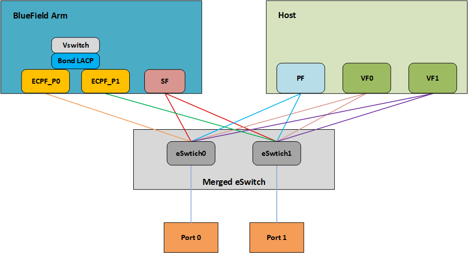
7.1. LAG Modes
Two LAG modes are supported on BlueField:
- Queue Affinity mode
- Hash mode
7.1.1. Queue Affinity Mode
In this mode, packets are distributed according to the QPs. To enable this mode, run:
$ mlxconfig -d /dev/mst/mt41686_pciconf0 s LAG_RESOURCE_ALLOCATION=0
Add/edit the following field from /etc/mellanox/mlnx-bf.conf as follows:
LAG_HASH_MODE="no"
Perform system power cycle.
7.1.2. Hash Mode
In this mode, packets are distributed to ports according to the hash on packet headers.
For this mode, prerequisite steps 3 and 4 are not required.
To enable this mode, run:
$ mlxconfig -d /dev/mst/mt41686_pciconf0 s LAG_RESOURCE_ALLOCATION=1
Add/edit the following field from /etc/mellanox/mlnx-bf.conf as follows:
LAG_HASH_MODE="yes"
Perform system power cycle.
7.2. Prerequisites
- Set the LAG mode to work with.
- (Optional) Hide the second PF on the host. Run:
$ mlxconfig -d /dev/mst/<device-name> s HIDE_PORT2_PF=True NUM_OF_PF=1
mt41686_pciconf0.Note:This step necessitates a system power cycle. If not performed, the second physical interface will still be visible to the host, but it will not be functional. This step has no effect on LAG configuration or functionality on the Arm side.
- Delete any installed Scalable Functions (SFs) on the Arm side.
- Stop the driver on the host side. Run:
$ systemctl stop openibd
- The uplink interfaces (p0 and p1) on the Arm side must be disconnected from any OVS bridge.
7.3. LAG Configuration
- Create the bond interface:
            $ ip link add bond0 type bond
$ ip link set bond0 down
$ ip link set bond0 type bond miimon 100 mode 4 xmit_hash_policy layer3+4
Note:While LAG is being configured (starting with the next step), traffic cannot pass through the physical ports.
- Subordinate both the uplink representors to the bond interface. Run:
            $ ip link set p0 down
$ ip link set p1 down
$ ip link set p0 master bond0
$ ip link set p1 master bond0
- Bring the interfaces up. Run:
            $ ip link set p0 up
$ ip link set p1 up
$ ip link set bond0 up
            # cat /etc/network/interfaces

# interfaces(5) file used by ifup(8) and ifdown(8)
# Include files from /etc/network/interfaces.d:
source /etc/network/interfaces.d/*
auto lo
iface lo inet loopback
#p0
auto p0
iface p0 inet manual
        bond-master bond1
#
#p1
auto p1
iface p1 inet manual
        bond-master bond1
#bond1
auto bond1
iface bond1 inet static
        address 192.168.1.1
        netmask 255.255.0.0
        mtu 1500
        bond-mode 2
        bond-slaves p0 p1
        bond-miimon 100
        pre-up (sleep 2 && ifup p0) &
        pre-up (sleep 2 && ifup p1) &
As a result, only the first PF of the DPU would be available to the host side for networking and SR-IOV.Warning:When in shared RQ mode (enabled by default), the uplink interfaces (p0 and p1) must always stay enabled. Disabling them will break LAG support and VF-to-VF communication on same host.
For OVS configuration, the bond interface is the one that needs to be added to the OVS bridge (interfaces p0 and p1 should not be added). The PF representor for the first port (pf0hpf) of the LAG must be added to the OVS bridge. The PF representor for the second port (pf1hpf) would still be visible, but it should not be added to OVS bridge. Consider the following examples:
            ovs-vsctl add-br bf-lag
ovs-vsctl add-port bf-lag bond0
ovs-vsctl add-port bf-lag pf0hpf
When performing driver reload (openibd restart) or reboot, it is required to remove bond configuration from NetworkManager, and to reapply the configurations after the driver is fully up. Refer to steps 1-4 of section Removing LAG Configuration.
7.4. Removing LAG Configuration
- If Queue Affinity mode LAG is configured (i.e.,
LAG_RESOURCE_ALLOCATION=0):- Delete any installed Scalable Functions (SFs) on the Arm side. Refer to Scalable Function Setup Guide for instructions on deleting SFs.
- Stop driver (openibd) on the host side. Run:
systemctl stop openibd
- Delete the LAG OVS bridge on the Arm side. Run:
$ ovs-vsctl del-br bf-lag
This allows for later restoration of OVS configuration for non-LAG networking.
- Stop OVS service. Run:
$ systemctl stop openvswitch-switch.service
- Run:
            $ ip link set bond0 down
$ modprobe -rv bonding
As a result, both of the DPU's network interfaces would be available to the host side for networking and SR-IOV.
- For the host to be able to use the DPU ports, make sure to attach the ECPF and host representor in an OVS bridge on the Arm side. Refer to "index.html#virtual-switch-on-dpu" for instructions on how to perform this.
- Revert from
HIDE_PORT2_PF, on the Arm side. Run:mlxconfig -d /dev/mst/<device-name> s HIDE_PORT2_PF=False NUM_OF_PF=2
- Restore default LAG settings in the DPU's firmware. Run:
mlxconfig -d /dev/mst/<device-name> s LAG_RESOURCE_ALLOCATION=DEVICE_DEFAULT
- Delete the following line from
/etc/mellanox/mlnx-bf.confon the Arm side:LAG_HASH_MODE=...
- Power cycle the system.
NVIDIA® BlueField® allows control over some of the networking parameters of the PFs and VFs running on the host side.
8.1. Setting Host PF and VF Default MAC Address
From the Arm, users may configure the MAC address of the physical function in the host. After sending the command, users must reload the NVIDIA driver in the host to see the newly configured MAC address. The MAC address goes back to the default value in the FW after system reboot. Example:
            $ echo "c4:8a:07:a5:29:59" > /sys/class/net/p0/smart_nic/pf/mac
$ echo "c4:8a:07:a5:29:61" > /sys/class/net/p0/smart_nic/vf0/mac
8.2. Setting Host PF and VF Link State
vPort state can be configured to Up, Down, or Follow. For example:
$ echo "Follow" > /sys/class/net/p0/smart_nic/pf/vport_state
8.3. Query Configuration
To query the current configuration, run:
            $ cat /sys/class/net/p0/smart_nic/pf/config
MAC        : e4:8b:01:a5:79:5e
MaxTxRate  : 0
State      : Follow
Zero signifies that the rate limit is unlimited.
8.4. Disabling Host Networking PFs
It is possible to not expose NVIDIA® ConnectX® networking functions to the host for users interested in using storage or VirtIO functions only. When this feature is enabled, the host PF representors (i.e., pf0hpf and pf1hpf) will not be seen on the Arm.
- Without a PF on the host, it is not possible to enable SR-IOV, so VF representors will not be seen on the Arm either
- Without PFs on the host, there can be no SFs on it
To disable host networking PFs, run:
mlxconfig -d /dev/mst/mt41686_pciconf0 s NUM_OF_PF=0
To reactivate host networking PFs, run:
- For single-port DPUs, run:
mlxconfig -d /dev/mst/mt41686_pciconf0 s NUM_OF_PF=1
- For dual-port DPUs, run:
mlxconfig -d /dev/mst/mt41686_pciconf0 s NUM_OF_PF=2
When there are no networking functions exposed on the host, the reactivation command must be run from the Arm.
Power cycle is required to apply configuration changes.
Notice
This document is provided for information purposes only and shall not be regarded as a warranty of a certain functionality, condition, or quality of a product. NVIDIA Corporation nor any of its direct or indirect subsidiaries and affiliates (collectively: “NVIDIA”) make no representations or warranties, expressed or implied, as to the accuracy or completeness of the information contained in this document and assume no responsibility for any errors contained herein. NVIDIA shall have no liability for the consequences or use of such information or for any infringement of patents or other rights of third parties that may result from its use. This document is not a commitment to develop, release, or deliver any Material (defined below), code, or functionality.
NVIDIA reserves the right to make corrections, modifications, enhancements, improvements, and any other changes to this document, at any time without notice.
Customer should obtain the latest relevant information before placing orders and should verify that such information is current and complete.
NVIDIA products are sold subject to the NVIDIA standard terms and conditions of sale supplied at the time of order acknowledgement, unless otherwise agreed in an individual sales agreement signed by authorized representatives of NVIDIA and customer (“Terms of Sale”). NVIDIA hereby expressly objects to applying any customer general terms and conditions with regards to the purchase of the NVIDIA product referenced in this document. No contractual obligations are formed either directly or indirectly by this document.
NVIDIA products are not designed, authorized, or warranted to be suitable for use in medical, military, aircraft, space, or life support equipment, nor in applications where failure or malfunction of the NVIDIA product can reasonably be expected to result in personal injury, death, or property or environmental damage. NVIDIA accepts no liability for inclusion and/or use of NVIDIA products in such equipment or applications and therefore such inclusion and/or use is at customer’s own risk.
NVIDIA makes no representation or warranty that products based on this document will be suitable for any specified use. Testing of all parameters of each product is not necessarily performed by NVIDIA. It is customer’s sole responsibility to evaluate and determine the applicability of any information contained in this document, ensure the product is suitable and fit for the application planned by customer, and perform the necessary testing for the application in order to avoid a default of the application or the product. Weaknesses in customer’s product designs may affect the quality and reliability of the NVIDIA product and may result in additional or different conditions and/or requirements beyond those contained in this document. NVIDIA accepts no liability related to any default, damage, costs, or problem which may be based on or attributable to: (i) the use of the NVIDIA product in any manner that is contrary to this document or (ii) customer product designs.
No license, either expressed or implied, is granted under any NVIDIA patent right, copyright, or other NVIDIA intellectual property right under this document. Information published by NVIDIA regarding third-party products or services does not constitute a license from NVIDIA to use such products or services or a warranty or endorsement thereof. Use of such information may require a license from a third party under the patents or other intellectual property rights of the third party, or a license from NVIDIA under the patents or other intellectual property rights of NVIDIA.
Reproduction of information in this document is permissible only if approved in advance by NVIDIA in writing, reproduced without alteration and in full compliance with all applicable export laws and regulations, and accompanied by all associated conditions, limitations, and notices.
THIS DOCUMENT AND ALL NVIDIA DESIGN SPECIFICATIONS, REFERENCE BOARDS, FILES, DRAWINGS, DIAGNOSTICS, LISTS, AND OTHER DOCUMENTS (TOGETHER AND SEPARATELY, “MATERIALS”) ARE BEING PROVIDED “AS IS.” NVIDIA MAKES NO WARRANTIES, EXPRESSED, IMPLIED, STATUTORY, OR OTHERWISE WITH RESPECT TO THE MATERIALS, AND EXPRESSLY DISCLAIMS ALL IMPLIED WARRANTIES OF NONINFRINGEMENT, MERCHANTABILITY, AND FITNESS FOR A PARTICULAR PURPOSE. TO THE EXTENT NOT PROHIBITED BY LAW, IN NO EVENT WILL NVIDIA BE LIABLE FOR ANY DAMAGES, INCLUDING WITHOUT LIMITATION ANY DIRECT, INDIRECT, SPECIAL, INCIDENTAL, PUNITIVE, OR CONSEQUENTIAL DAMAGES, HOWEVER CAUSED AND REGARDLESS OF THE THEORY OF LIABILITY, ARISING OUT OF ANY USE OF THIS DOCUMENT, EVEN IF NVIDIA HAS BEEN ADVISED OF THE POSSIBILITY OF SUCH DAMAGES. Notwithstanding any damages that customer might incur for any reason whatsoever, NVIDIA’s aggregate and cumulative liability towards customer for the products described herein shall be limited in accordance with the Terms of Sale for the product.
Trademarks
NVIDIA, the NVIDIA logo, and Mellanox are trademarks and/or registered trademarks of Mellanox Technologies Ltd. and/or NVIDIA Corporation in the U.S. and in other countries. The registered trademark Linux® is used pursuant to a sublicense from the Linux Foundation, the exclusive licensee of Linus Torvalds, owner of the mark on a world¬wide basis. Other company and product names may be trademarks of the respective companies with which they are associated.
Copyright
© 2023 NVIDIA Corporation & affiliates. All rights reserved.