cuStateVec Ex: State Vector Distribution#
cuStateVec Ex provides three state vector distribution models to support different scales of quantum circuit simulations. In this section, the configurations are elaborated for multi-device and multi-process state vectors.
Multi-Device State Vector#
In the distribution model of multi-device state vector, single process owns multiple devices.
Device network type#
For multi-device state vector, two types of device network topologies are supported. By specifying the device network topology, data transfers between devices are optimally scheduled.
Switch network: All devices are connected through a central switch.
Mesh network: All devices are directly connected to each other.
The device network type is chosen by specifying CUSTATEVEC_DEVICE_NETWORK_TYPE_SWITCH or CUSTATEVEC_DEVICE_NETWORK_TYPE_FULLMESH to the networkType argument in custatevecExConfigureStateVectorMultiDevice().
All the connections between devices should support GPUDirect P2P.

Device network topology for multi-device state vectors#
Example#
Let us assume that 4 devices will be utilized to allocate 30 wire state vector.
numWires and numDeviceWires should satisfy the following relationship:
numWires = log2(numDevices) + numDeviceWires
where log2(numDevices) represents the global index bits used for inter-device communication, and numDeviceWires represents the local qubits on each device.
The 30-wire state vector is equally sliced into four devices that corresponds to 2 wires (= log2(4)). Thus, each device allocates a 28-wire state vector.
// Configure multi-device state vector with 4 GPUs
int deviceIds[] = {0, 1, 2, 3};  // Those devices should belong to the same generation.
int numDevices = 4;
int numDeviceWires = 28;  // Local wires per device
int numWires = 30;  // log2(4) + 28 = 2 + 28 = 30 total wires

custatevecExDictionaryDescriptor_t svConfig;
custatevecExConfigureStateVectorMultiDevice(&svConfig, CUDA_C_64F, numWires, numDeviceWires,
                                            deviceIds, numDevices,
                                            CUSTATEVEC_DEVICE_NETWORK_TYPE_SWITCH, 0);

// Create CUDA streams for each device
cudaStream_t streams[4];
for (int i = 0; i < numDevices; i++) {
    cudaSetDevice(deviceIds[i]);
    cudaStreamCreate(&streams[i]);
}

// Create multi-device state vector
custatevecExStateVectorDescriptor_t stateVector;
custatevecExStateVectorCreateSingleProcess(&stateVector, svConfig, streams, numDevices, nullptr);

// Clean up configuration
custatevecExDictionaryDestroy(svConfig);
Configuration is created using custatevecExConfigureStateVectorMultiDevice() and instantiated with custatevecExStateVectorCreateSingleProcess().
Multi-Process State Vector#
In the distribution model of multi-process state vector, the state vector is allocated across multiple processes, and each process owns one device.
Communicator#
Communicator is the abstraction of inter-process communication (IPC) library in cuStateVec Ex API. It is a thin glue layer to interface cuStateVec Ex API and IPC libraries. The cuStateVec library provides two built-in communicator implementations to utilize Open MPI and MPICH. In order to utilize other IPC libraries, one can build custom communicators.
Memory Sharing Methods#
Multi-process state vector can utilize GPUDirect P2P between processes. The method to enable GPUDirect P2P is called the memory sharing method in cuStateVec Ex API.
The current release supports two sharing methods:
PidFd
CUSTATEVEC_EX_MEMORY_SHARING_METHOD_PIDFDIt uses POSIX file descriptor to export the allocated memory to other processes, and import the exported memory from other processes.
In order to share the file descriptor, cuStateVec Ex API uses Linux syscalls, SYS_pidfd_open and SYS_pidfd_getfd, that are supported by Linux kernel 5.6 or later.
The GPUDirect P2P is enabled among devices in a single hardware box.
Fabric Handle
CUSTATEVEC_EX_MEMORY_SHARING_METHOD_FABRIC_HANDLEFabric Handle is mandatory to use multi-node NVLink for systems such as GB200 NVL36 and GB200 NVL72.
Auto-detect (CUSTATEVEC_EX_MEMORY_SHARING_METHOD_AUTODETECT) detects the available memory sharing method. If the use of GPUDirect P2P is not required, memory sharing method will be None (CUSTATEVEC_EX_MEMORY_SHARING_METHOD_NONE).
Layered network#
Multi-process state vectors support layered networks with multiple communication layers. Each layer represents a different communication datalink (e.g., PCIe Switch, NVLink with NVSwitch, InfiniBand). This model is frequently seen in modern HPC clusters, where data transfers are assumed to be faster in lower layers and slower in higher layers. This layered model enables optimal scheduling of data transfers by using faster data links more frequently, reducing overall data transfer overhead.
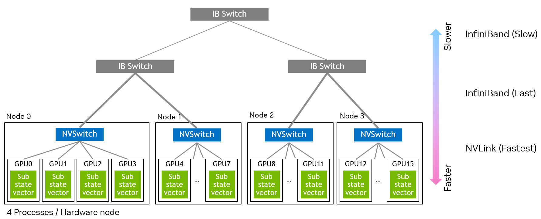
Layered multi-node network architecture#
The above figure shows an example of a cluster configuration. There are four devices in the lowest layer where the NVLink connects those devices. In the middle layer, InfiniBand switch connects two hardware nodes. The top layer connects two InfiniBand switches in the middle layer.
Each layer is characterized by Global Index Bit Class and Number of Global Index Bits.
The Global Index Bit Class determines the communication method for each layer.
CUSTATEVEC_EX_GLOBAL_INDEX_BIT_CLASS_INTERPROC_P2P: Uses GPUDirect P2P for direct GPU-to-GPU communication between processes. MemorySharingMethod, PidFd or Fabric Handle, should be available.CUSTATEVEC_EX_GLOBAL_INDEX_BIT_CLASS_COMMUNICATOR: Uses communicator for inter-process communication. Data transfers go through the IPC library that is encapsulated by the communicator.CUSTATEVEC_EX_GLOBAL_INDEX_BIT_CLASS_MIGRATION: Uses host memory as extended storage. The sub state vectors for these global index bits are partially stored on host memory and staged to device on demand. See Migration layer.
Example: Configuring the layered network
For the cluster shown in the figure above with 16 total GPUs (4 GPUs per node × 4 nodes), the layers would be configured as follows:
// Configure hierarchical network with 3 layers for 16 GPUs (4 nodes × 4 GPUs/node)
custatevecExGlobalIndexBitClass_t globalIndexBitClasses[3];
int32_t numGlobalIndexBitsPerLayer[3];

// Layer 0 (lowest): Intra-node GPU communication via NVLink
// 4 GPUs per node = 2^2, so 2 global index bits
globalIndexBitClasses[0] = CUSTATEVEC_EX_GLOBAL_INDEX_BIT_CLASS_INTERPROC_P2P;
numGlobalIndexBitsPerLayer[0] = 2;  // 4 GPUs per node, 2 index bits = log(4 devices)

// Layer 1 (middle): Inter-node communication within same InfiniBand switch
// 2 nodes per switch = 2^1, so 1 global index bit
globalIndexBitClasses[1] = CUSTATEVEC_EX_GLOBAL_INDEX_BIT_CLASS_COMMUNICATOR;
numGlobalIndexBitsPerLayer[1] = 1;  // 2 nodes per switch, 1 index bit = log(2 nodes)

// Layer 2 (top): Communication between InfiniBand switches
// 2 switches = 2^1, so 1 global index bit
globalIndexBitClasses[2] = CUSTATEVEC_EX_GLOBAL_INDEX_BIT_CLASS_COMMUNICATOR;
numGlobalIndexBitsPerLayer[2] = 1;  // 2 switches, 1 index bit = log(2 switches)
The above arrays will be passed to custatevecExConfigureStateVectorMultiProcess() to specify the network structure.
Process rank assignment#
Every process owns its process rank assigned by the IPC library (MPI). The process rank is mapped to the inter-process global index bits (the INTERPROC_P2P and COMMUNICATOR layers); the migration bits are local to a process and do not reflect the process rank.
The process rank is the inter-process global index bits read as an integer, with lower layers occupying the less significant bits. For the 16-process example above:
Rank bits |
Layer |
Selects |
Communication |
|---|---|---|---|
bits 0-1 |
Layer 0 |
GPU within the P2P group (NVLink) |
inter-process P2P |
bit 2 |
Layer 1 |
node within the InfiniBand switch |
communicator |
bit 3 |
Layer 2 |
InfiniBand switch |
communicator |
For example, process rank 10 (binary 1010) decomposes as bits 0-1 = 10 (GPU 2), bit 2 = 0 (node 0 within the switch), and bit 3 = 1 (switch 1).
Mapping between a process rank and global index bits for the three-layer network example. Process rank 10 maps to sub state vector index 10.#
Use host memory as extended storage#
A multi-process state vector can use host memory as the extended storage of state vector by including a single migration layer specified by CUSTATEVEC_EX_GLOBAL_INDEX_BIT_CLASS_MIGRATION. The sub state vectors corresponding to its global index bits are partially stored on host memory and staged to device on demand. For the migration mechanism, see State Vector Migration. Among distributed state vector configurations, migration is supported only by multi-process configurations; multi-device configurations do not support it.
The migration layer has the following characteristics that differ from inter-process communication layers:
It can appear at most once in the
globalIndexBitClassesarray.Like inter-process layers, it participates in the layered network model where lower layers are faster and higher layers are slower. Place it in the layer ordering according to the relative speed of host-device migration, so that host-device transfers are scheduled consistently with inter-process transfers.
It does not increase the number of processes. The number of processes is determined only by the inter-process layers (
INTERPROC_P2PandCOMMUNICATOR):numProcesses = 1 << (sum of global index bits of inter-process layers)
The migration global index bits extend the state vector using host memory. The total number of wires includes the migration bits:
numWires = numDeviceWires + (sum of global index bits of all layers, including migration)
The number of migration wires must not exceed the number of local (device) wires.
The following example adds a migration layer to the layered network configuration shown above:
// A migration layer can be placed at any position among the layers.
// Here it is inserted as layer 2, between two inter-process layers.
custatevecExGlobalIndexBitClass_t globalIndexBitClasses[4];
int32_t numGlobalIndexBitsPerLayer[4];

globalIndexBitClasses[0] = CUSTATEVEC_EX_GLOBAL_INDEX_BIT_CLASS_INTERPROC_P2P;
numGlobalIndexBitsPerLayer[0] = 2;
globalIndexBitClasses[1] = CUSTATEVEC_EX_GLOBAL_INDEX_BIT_CLASS_COMMUNICATOR;
numGlobalIndexBitsPerLayer[1] = 1;

// Migration layer: extends each process's sub state vector using host memory
globalIndexBitClasses[2] = CUSTATEVEC_EX_GLOBAL_INDEX_BIT_CLASS_MIGRATION;
numGlobalIndexBitsPerLayer[2] = 1;  // 1 migration wire (2x via host memory)

globalIndexBitClasses[3] = CUSTATEVEC_EX_GLOBAL_INDEX_BIT_CLASS_COMMUNICATOR;
numGlobalIndexBitsPerLayer[3] = 1;
The migration layer does not change the number of processes (still 16), while it doubles the state vector size by using host memory.
When a migration layer is included, a process holds more than one sub state vector: one staged on its device and the others residing on host memory. A process is identified by its inter-process global index bits, while its sub state vectors differ only in the migration bits. Because inter-process bits occupy positions below the migration bits, these sub state vectors are not adjacent; they are strided in the global sub state vector index space.
For example, consider a configuration with a P2P layer of 2 global index bits (4 processes) and a migration layer of 1 global index bit, as shown in the figure below. The inter-process bits occupy the least significant positions (bits 0-1) and the migration bit occupies the most significant position (bit 2). Process rank 0 then holds the sub state vectors with global indices 0 (staged, migration bit = 0) and 4 (unstaged, migration bit = 1), and process rank 2 holds the sub state vectors with global indices 2 (staged, migration bit = 0) and 6 (unstaged, migration bit = 1). In both cases the indices within a process are strided by the number of processes.
Sub state vector indices for a configuration with a P2P layer and a migration layer. (a) Rank 0 holds sub state vector indices 0 and 4. (b) Rank 2 holds sub state vector indices 2 and 6. The indices within a process are strided by the number of processes.#
Example#
The following example shows steps to configure, instantiate, and destroy multi-process state vector. The number of wires (qubits) is 36 and that of all global wires is 4. Thus, each device will allocate a 32-wire sub state vector.
// On the application launch
// Initialize communicator library
custatevecExCommunicatorStatus_t commStatus;
custatevecExCommunicatorInitialize(CUSTATEVEC_COMMUNICATOR_TYPE_OPENMPI, nullptr,
                                   &argc, &argv, &commStatus);

// Create MPI communicator
custatevecExCommunicatorDescriptor_t communicator;
custatevecExCommunicatorCreate(&communicator);

// Configure multi-process state vector
custatevecExDictionaryDescriptor_t svConfig;
const int32_t numWires = 36;  // 36 qubits total
const int32_t numDeviceWires = 32;  // 32 qubits per device
const cudaDataType_t svDataType = CUDA_C_32F;

// Build arrays for hierarchical network configuration (3 layers for 16 GPUs)
custatevecExGlobalIndexBitClass_t globalIndexBitClasses[3];
int32_t numGlobalIndexBitsPerLayer[3];

// Layer 0 (lowest): Intra-node GPU communication via NVLink
globalIndexBitClasses[0] = CUSTATEVEC_EX_GLOBAL_INDEX_BIT_CLASS_INTERPROC_P2P;
numGlobalIndexBitsPerLayer[0] = 2;  // 4 GPUs per node, 2 index bits = log(4 devices)

// Layer 1 (middle): Inter-node communication within same InfiniBand switch
globalIndexBitClasses[1] = CUSTATEVEC_EX_GLOBAL_INDEX_BIT_CLASS_COMMUNICATOR;
numGlobalIndexBitsPerLayer[1] = 1;  // 2 nodes per switch, 1 index bit = log(2 nodes)

// Layer 2 (top): Communication between InfiniBand switches
globalIndexBitClasses[2] = CUSTATEVEC_EX_GLOBAL_INDEX_BIT_CLASS_COMMUNICATOR;
numGlobalIndexBitsPerLayer[2] = 1;  // 2 switches, 1 index bit = log(2 switches)

custatevecExConfigureStateVectorMultiProcess(
    &svConfig, svDataType, numWires, numDeviceWires,
    -1,  // Auto-detect deviceId
    CUSTATEVEC_EX_MEMORY_SHARING_METHOD_AUTODETECT,
    globalIndexBitClasses, numGlobalIndexBitsPerLayer,
    3,  // 3 hierarchical layers
    0,  // transferWorkspace
    nullptr, 0);  // auxConfig, capability

// Instantiate the state vector
custatevecExStateVectorDescriptor_t stateVector;
custatevecExStateVectorCreateMultiProcess(&stateVector, svConfig, stream, communicator, nullptr);

// Simulator main logic

// Clean up
custatevecExDictionaryDestroy(svConfig);
custatevecExCommunicatorDestroy(communicator);

// On the application shutdown
custatevecExCommunicatorFinalize(&commStatus);
The relationship between total qubits and per-device qubits is:
numWires = log2(numProcesses) + numDeviceWires
where log2(numProcesses) represents the global index bits distributed across processes, and numDeviceWires represents the local qubits per process.