Getting Started#
This guide will help you access and start using the VSS Auto Calibration Microservice and User Interface.
Prerequisites#
Before using the microservice and UI, ensure you have:
System Requirements
x86_64 system
OS Ubuntu 24.04
NVIDIA GPU with hardware encoder (NVENC)
NVIDIA driver 590
Docker (setup to run without sudo privilege)
NVIDIA container toolkit (Refer to the Prerequisites section)
Required
One or more camera video files (MP4) or time-synchronized RTSP streams; one for single-camera calibration, or at least two for multi-camera
Layout/map image (PNG format)
Optional
Ground truth data (ZIP file) for calibration evaluation
Pre-existing alignment data (JSON file)
Focal length values for cameras
Config parameters if any for your dataset
Deployment Steps (Docker Compose)
Note
To automate Auto Calibration deployment and calibration with the bundled VSS Agent Skills instead of following the manual steps below, see the Agent Skills walkthrough later in this guide.
Deploy the UI and backend microservice using Docker Compose. Refer to the Warehouse Blueprint Introduction for more details.
To use RTSP capture via VIOS, ensure the VIOS server is set up and running. Set VIOS_BASE_URL in the .env file as described in the deployment environment variable setup.
Setup NGC access and authenticate Docker to pull images from
nvcr.io:# Setup NGC access export NGC_CLI_API_KEY=<NGC_CLI_API_KEY> export NGC_CLI_ORG='nvidia' # Authenticate Docker to nvcr.io (required before docker compose pull/up) docker login nvcr.io -u '$oauthtoken' -p "${NGC_CLI_API_KEY}"
Generate an NGC API key from NGC Setup if you do not already have one. Docker must be logged in to
nvcr.iobefore the containers in the steps below can be pulled.Download deployment resources by cloning the Git repository:
git clone https://github.com/NVIDIA-AI-Blueprints/video-search-and-summarization.git
cd video-search-and-summarization
git checkout tags/v3.2.0
Navigate to the VSS Auto Calibration directory:
cd deploy/docker/services/auto-calibration
Your directory structure should be:
├── compose.yml
├── ms
│   └── compose.yml
└── ui
    └── compose.yml
Create a
.envfile in your current directory with the following environment variables:VSS_AUTO_CALIBRATION_PORT=8000 VSS_AUTO_CALIBRATION_UI_PORT=5000 VSS_APPS_DIR=/path/to/video-search-and-summarization/deploy/docker VSS_DATA_DIR=/path/to/your/data_dir HOST_IP=<HOST_IP_ADDRESS> # VIOS_BASE_URL=http://<VIOS_HOST_IP>:30888 # Uncomment and update this to support RTSP Stream input
Replace the paths, ports and IP address with your actual values.
Note
This guide sets
VSS_AUTO_CALIBRATION_PORT=8000in.env, which maps the backend to port 8000 on the host. The Auto Calibration servicecompose.ymlin the repository may use a different default (for example 8010) whenVSS_AUTO_CALIBRATION_PORTis not set—always use the port you configured in.envwhen opening the API or troubleshooting connectivity.Download and set up the VGGT model and create projects directory:
Download the VGGT commercial model from HuggingFace.
Note
You need to sign up for a HuggingFace account and accept the model license to download.
Move the downloaded model file (
vggt_1B_commercial.pt) to the VGGT model directory:mkdir -p ${VSS_DATA_DIR}/auto-calib/vggt mv vggt_1B_commercial.pt ${VSS_DATA_DIR}/auto-calib/vggt/
Create projects directory:
mkdir -p ${VSS_APPS_DIR}/services/auto-calibration/projects
Note
Projects will be saved in:
${VSS_APPS_DIR}/services/auto-calibration/projectsChange the ownership of the directory to UID 1000 and GID 1000:
sudo chown -R 1000:1000 ${VSS_DATA_DIR}/auto-calib
sudo chown -R 1000:1000 ${VSS_APPS_DIR}/services/auto-calibration/projects
Ensure you have access to NGC to pull the containers.
Start both the microservice and UI servers:
docker compose --profile "auto_calib" up -d
Open your browser and navigate to:
http://<HOST_IP>:<VSS_AUTO_CALIBRATION_UI_PORT>
For example, with the default settings:
http://<HOST_IP>:5000To stop the containers
docker compose --profile "auto_calib" down
First Time Setup#
When you first access the UI, you’ll see the main interface with a stepper showing 6 workflow steps.
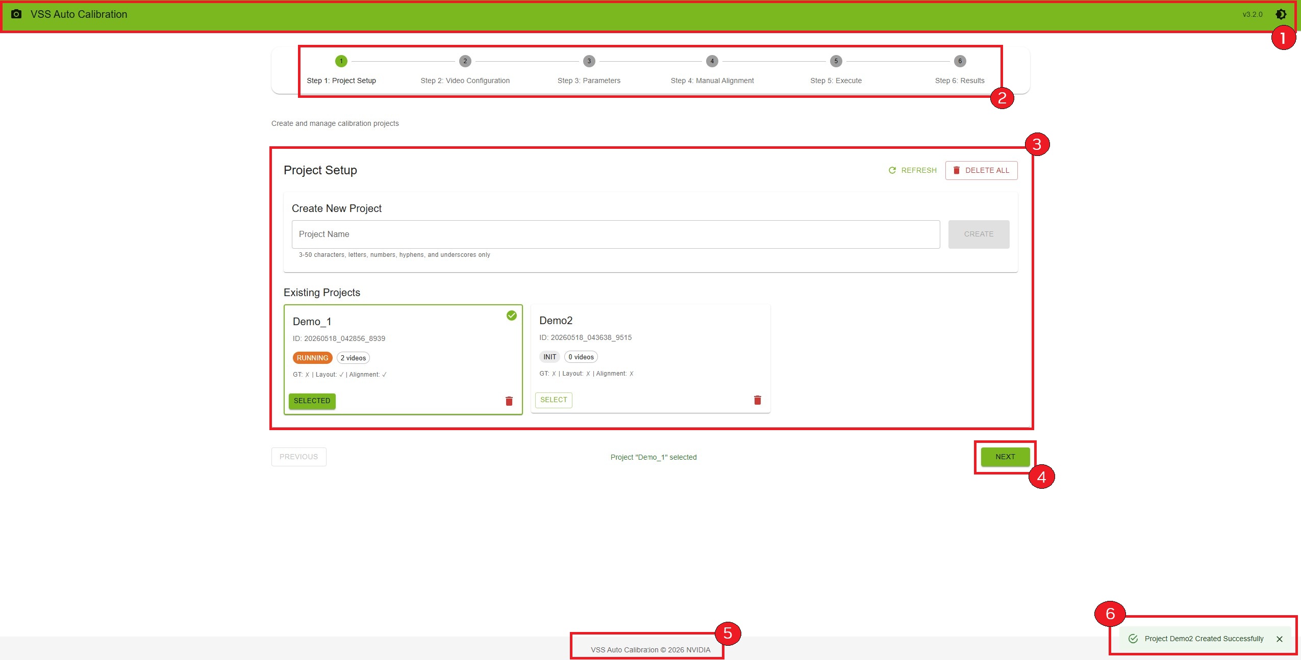
Interface Overview
The interface consists of:
Header Bar
Application name and version
Theme toggle button (light/dark mode)
Stepper Navigation
Visual progress indicator
Click on steps to navigate (after selecting a project)
Current step is highlighted
Main Content Area
Step-specific content and controls
Forms, file uploads, and interactive tools
Navigation Buttons
“Previous” button to go back
“Next” button to proceed
Disabled when requirements aren’t met
Footer
Copyright information
Application version
Notifications
Success/error messages appear in bottom-right corner
Auto-dismiss after 6 seconds
Quick Start Guide#
Follow these steps to perform your first calibration:
Step 0: Deploy the UI (If Not Already Running)
If you’re deploying via Docker Compose, follow the steps in the Deployment Steps (Docker Compose) section above. Once deployed, access the UI at http://<HOST_IP>:<VSS_AUTO_CALIBRATION_UI_PORT> (default: port 5000).
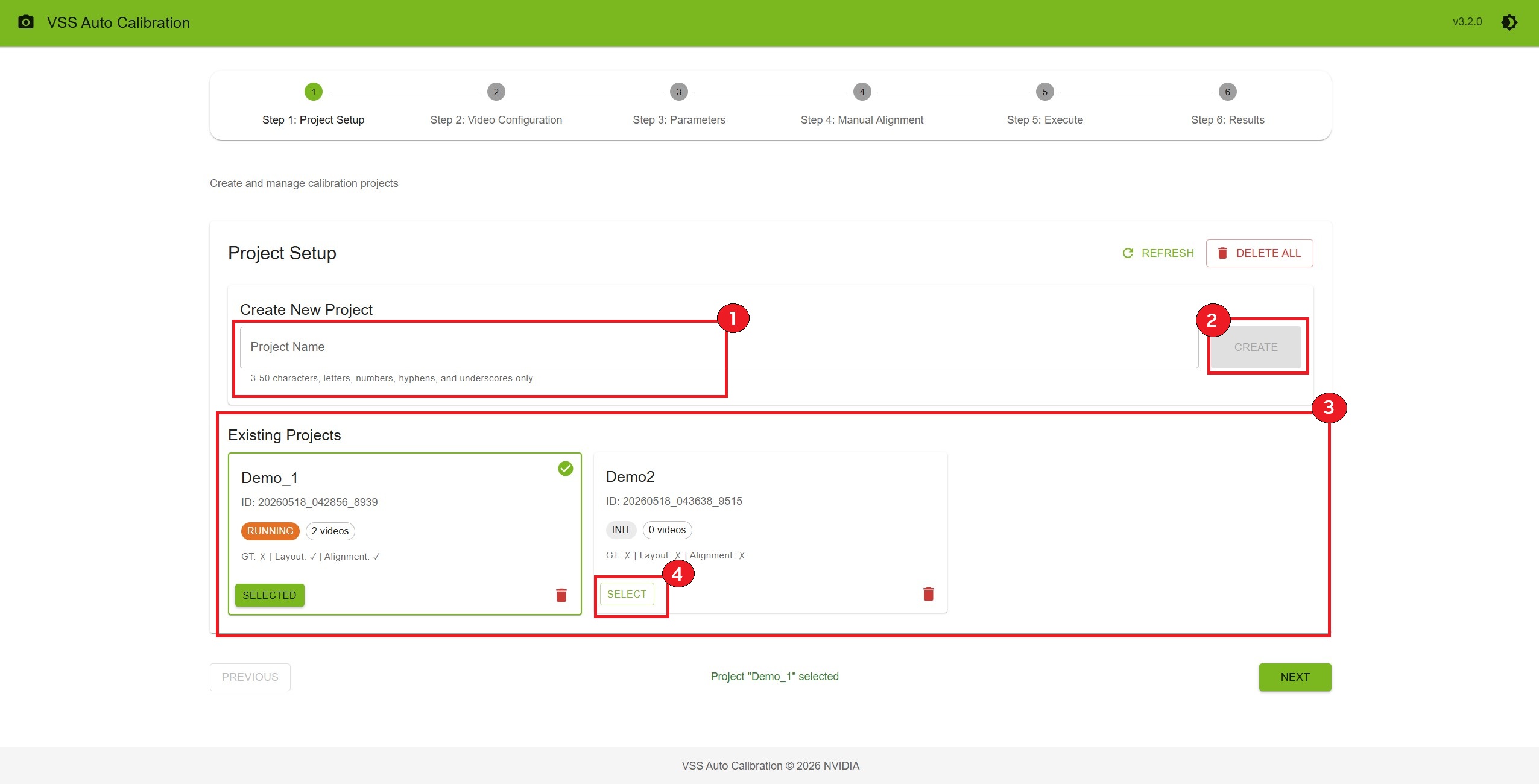
Step 1: Create a Project
On the Project Setup page, enter a project name (e.g.,
warehouse_calibration)Click “Create” button
Your new project appears in the list below
Click “Select” on your project card
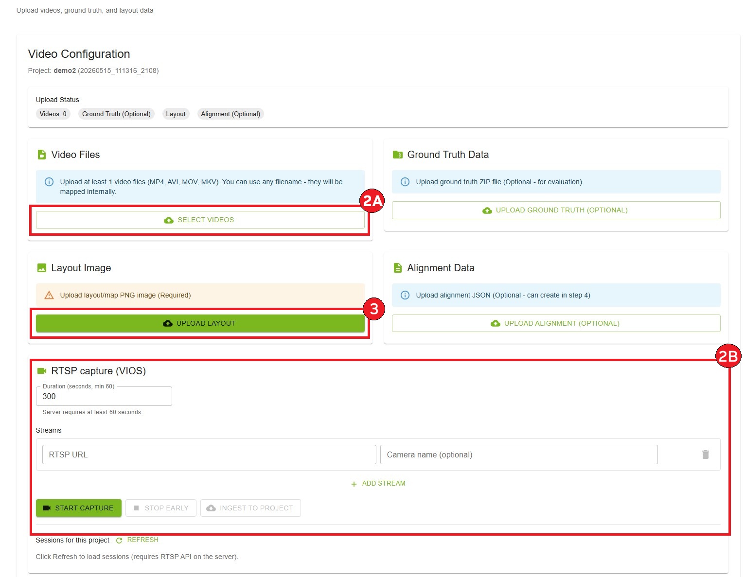
Step 2: Upload Files
Click “Next” to go to Video Configuration
Provide one or more time-synchronized camera inputs using either file upload or RTSP capture (one camera for single-camera calibration, two or more for multi-camera; the UI blocks mixing an active file upload queue with RTSP, and file-uploaded clips must be removed before switching to RTSP).
Option A: Upload video files
Click “Select Videos” button
Select video files named
cam_00.mp4,cam_01.mp4, etc.Reorder videos by dragging.
Click “Upload Videos” to upload the videos.
Option B: RTSP capture (VIOS) (shown only when the Auto Calibration service exposes RTSP capture; VIOS is configured on the server side)
Finish or clear any pending Video Files selection or upload before starting RTSP; if the project already has clips from file upload, remove them under Video Files before using RTSP.
In the RTSP capture (VIOS) card, set Duration (seconds). The server requires at least 60 seconds.
Under Streams, enter all camera RTSP URLs for this project in one session (use Add stream for additional cameras; one stream for single-camera, two or more for multi-camera). Optionally set Camera name for each stream.
Click Start capture once with every stream listed—capture runs for all streams together. Do not add streams at different times or run separate captures for different subsets; staggered captures break time synchronization.
Wait for recording to progress (status chip and progress bar). You may click Stop early only after at least 60 seconds of active recording have elapsed.
When the session is finished (COMPLETED or CANCELLED), click Ingest to project to add the captured clips to the project’s video list. While capture or ingest is running, Video Files upload stays disabled until the RTSP pipeline completes.
Note
RTSP inputs must be time-synchronized: configure every stream, then run one Start capture for the full set. Re-capturing or ingesting additional streams later (instead of a single combined capture) will desync clips and is not supported for calibration. List each RTSP URL in order of overlapping field of view (FOV)—the same ordering used when uploading video files (first stream = first camera in the overlap chain).
Note
For VIOS pre-registered RTSP streams, use the source URL (for example, the NVStreamer URL if the stream originates from NVStreamer) rather than the VIOS-proxied URL.
Upload layout image:
Click “Upload Layout” button
Select your PNG format layout/map image
Confirm upload success
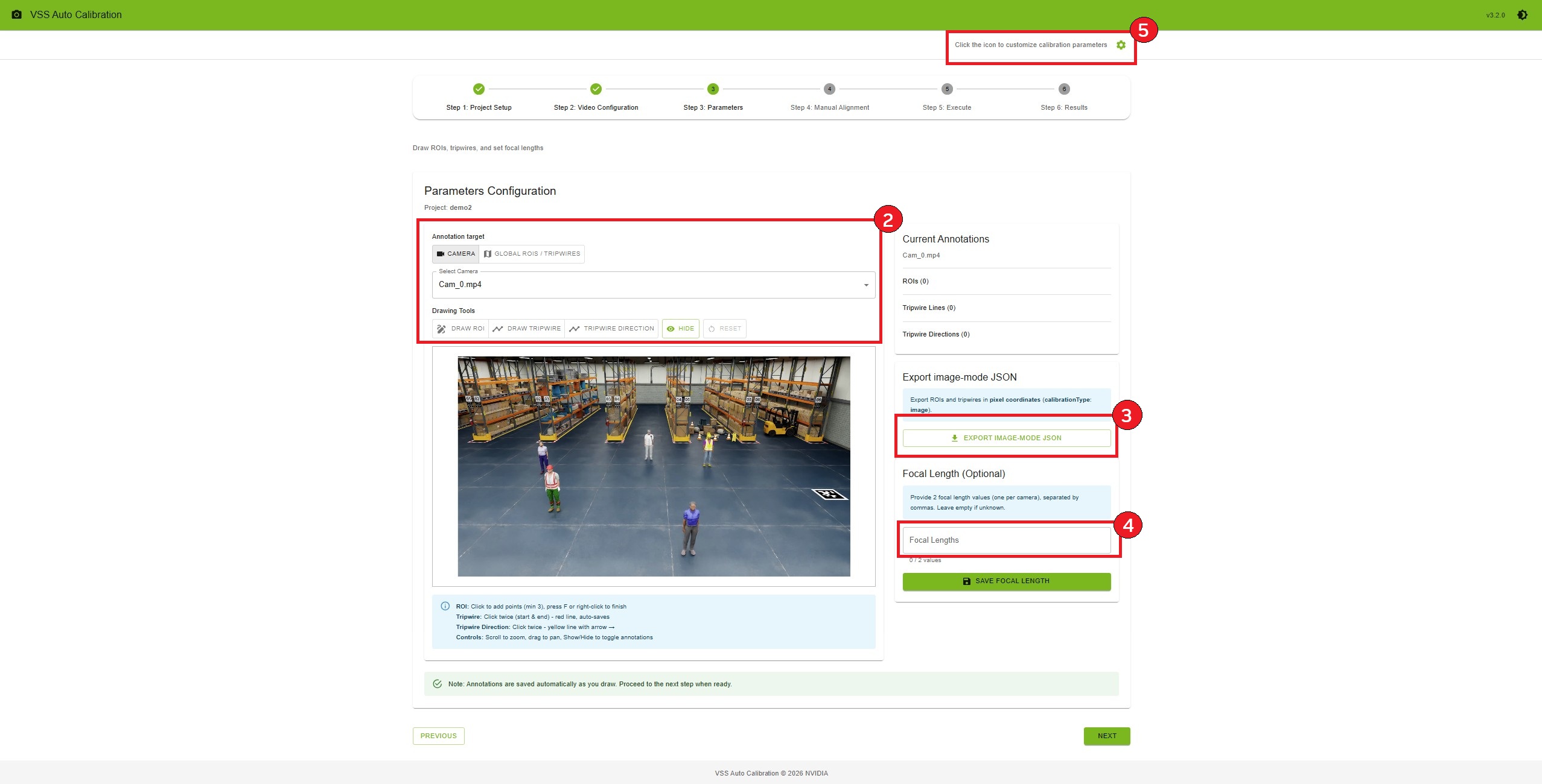
Step 3: Configure Parameters
Click “Next” to go to Parameters
Under Annotation target, choose where to draw ROIs and tripwires (all optional):
Camera — per-camera annotations on a video frame
Select a camera from Select Camera
Use Drawing Tools on the video frame:
Draw ROI: click to add points (minimum 3), press F or right-click to finish; saved automatically
Draw Tripwire: click twice for start and end (red line); saved automatically
Tripwire Direction: click twice for a directional line (yellow, with arrow); saved automatically
Global ROIs / tripwires — layout-map annotations (requires a layout image from Step 2)
Select Global ROIs / tripwires (disabled until layout.png is uploaded in Video Configuration)
Draw on the floor-plan / layout image using the same Drawing Tools (Draw ROI, Draw Tripwire, Tripwire Direction)
Global shapes are stored separately from per-camera annotations and appear under Current Annotations as Global (layout map)
For both targets you can use Show/Hide to toggle overlays and Reset to clear annotations for the active target.
Export image-mode JSON (optional, right panel):
Click Export image-mode JSON to download
<project_name>_image_mode_exported.jsonExports ROIs and tripwires in pixel coordinates (
calibrationType: image); bundle adjustment is not required for this export
Add focal lengths (optional):
Enter comma-separated values (one per camera)
Click “Save Focal Length”
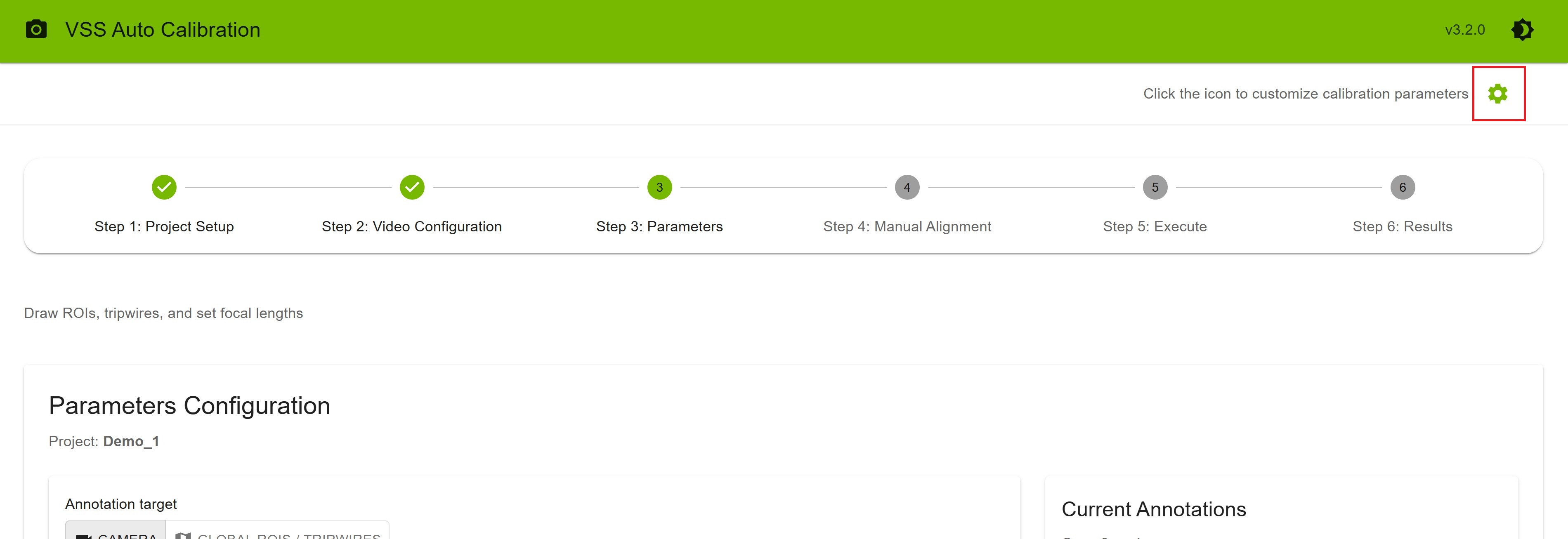
Configure parameters (optional):
On the Parameters step, click the Click the icon to customize calibration parameters icon in the top-right (visible only on this step)
Upload a pre-configured settings file, or manually adjust calibration parameters in the dialog
Use Download to export the current configuration, Reset to Defaults to restore defaults, then Save Settings
Make all changes before starting calibration in Step 5: Execute; do not change settings while AMC is running
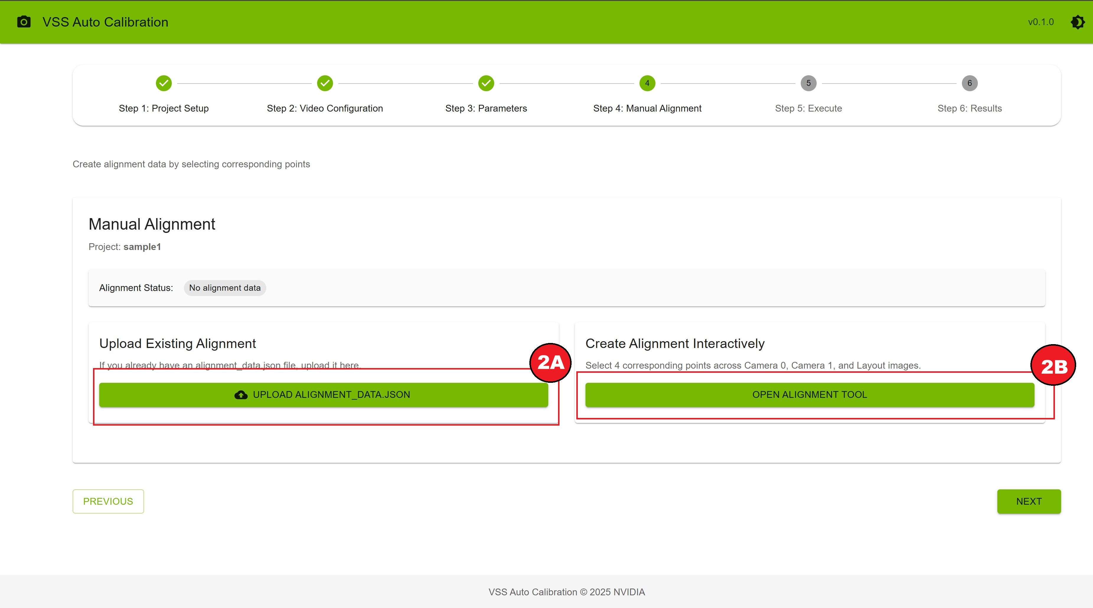
Step 4: Create Alignment Data
Click “Next” to go to Manual Alignment
Choose one of two options:
Option A: Upload Existing Alignment
Click “Upload alignment_data.json”
Select your JSON file
Wait for upload confirmation
Option B: Create Alignment Interactively
Click “Open Alignment Tool”
Click the same physical point on Camera 0, Camera 1, and Layout (in order)
Repeat for at least 4 different points
Click “Save Alignment” when complete
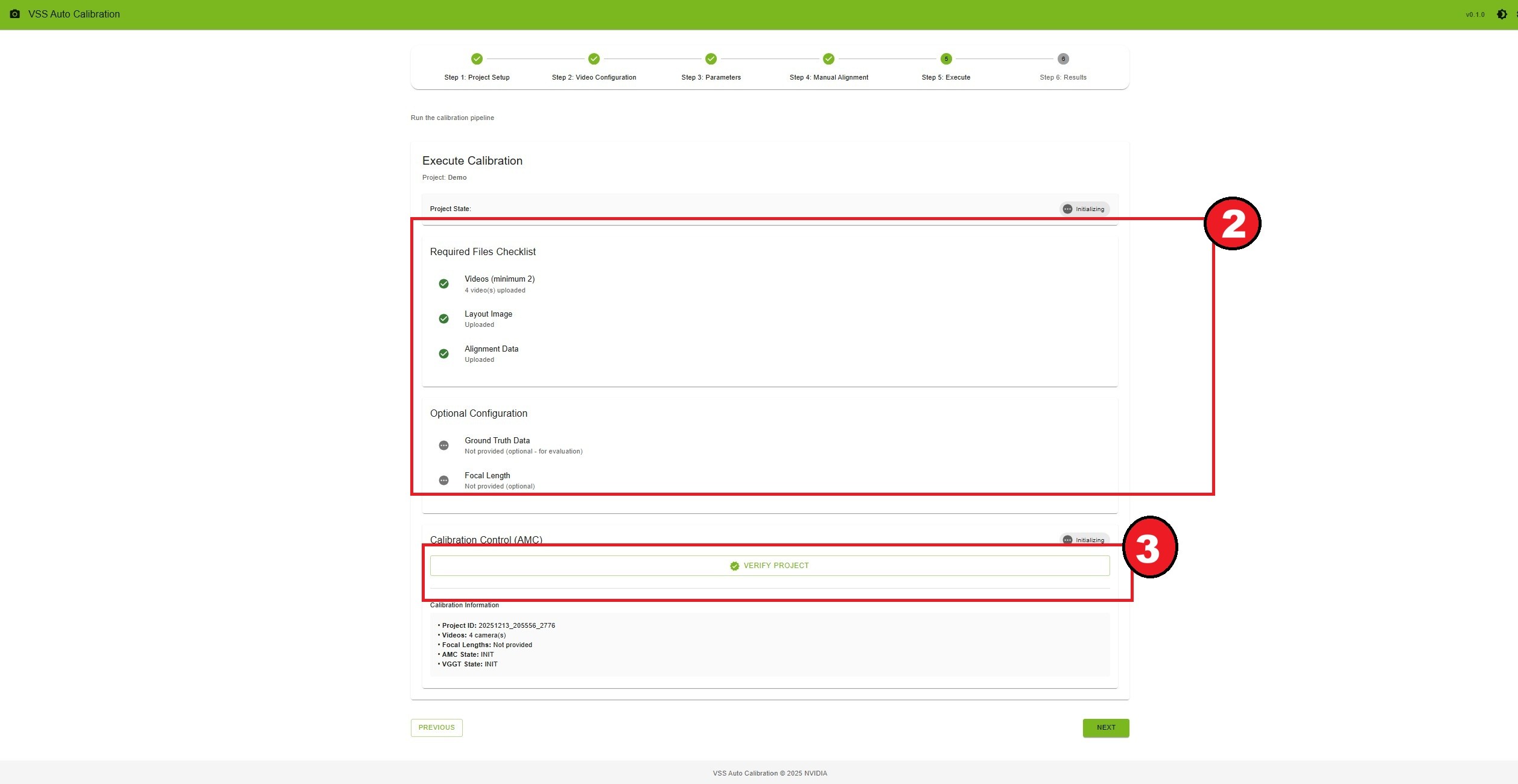
Step 5: Run Calibration
Click “Next” to go to Execute
Review the requirements checklist
Click “Verify Project” button
Once verified, click “Start Calibration”
Monitor the progress (status updates every 3 seconds)
Wait for “Calibration completed successfully” message (AMC), or for AMC to finish far enough that optional VGGT can run (see below)
Step 5b: Run VGGT Calibration (Optional, Multi-Camera Only)
VGGT (Vision-Geometry Graph Transformer) is an optional model-based calibration path. It is available only when the backend has the VGGT model installed (see Deployment Steps above) and your project has two or more cameras—single-camera projects do not support VGGT.
After Start Calibration (AMC) has run and produced on-disk outputs (typically after rectification), scroll to Calibration Control (VGGT) on the Execute step
Confirm VGGT state is READY (AMC does not need to show COMPLETED; VGGT can remain runnable if AMC failed after rectification)
Click Run VGGT Calibration and monitor progress
When VGGT completes successfully, the project state becomes COMPLETED even if AMC failed—you can proceed to Results using the VGGT tab
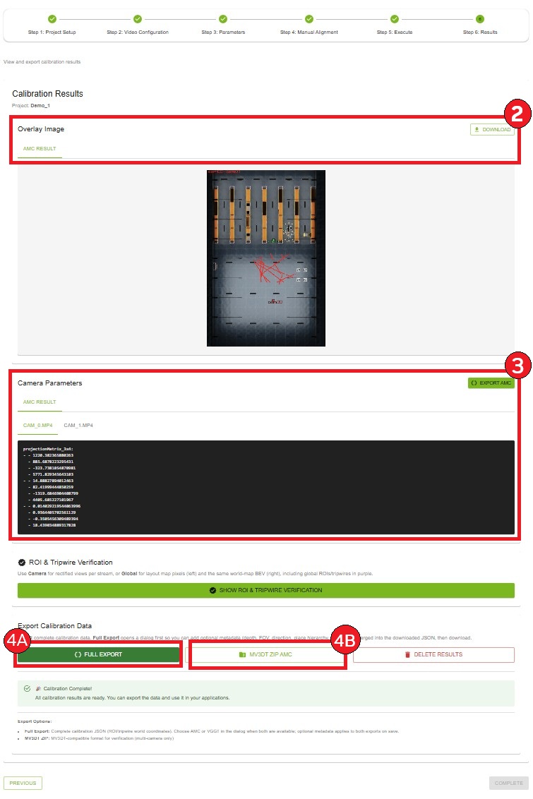
Step 6: View Results
Click “Next” to go to Results
View the overlay image showing calibration results. Click “Download” to save overlay image
Review camera parameters for each camera
Export calibration data:
Click “Full Export AMC” for complete calibration data. It will load the json which contains the calibration data for all the cameras in the project, which you can edit according to your usecase.
Click “MV3DT ZIP AMC” for MV3DT-compatible format
Settings#
Click the settings icon in the top-right corner to access calibration parameters. Note: The settings icon is only visible when you are on the Parameters step.
Additional Available Settings
Theme: Switch between light and dark themes
Version Information: View current application version
Note: Most settings are configured during deployment and cannot be changed from the UI.
Agent Skills walkthrough#
This section walks through the Auto Calibration user journeys using a coding agent (Claude Code, Codex, or
NemoClaw) and the vss-generate-video-calibration Agent Skill.
For each journey it documents the example prompt you give the agent and
what the agent does in response.
Note
Install the skills into your coding agent first (see Installing Skills for the install flow). For how each harness loads skills, see Agent Harnesses.
The agent may pause for user input during the journey. Common prompts include
NGC_CLI_API_KEY for NGC image pulls, HF_TOKEN when staging the VGGT
model, VSS_APPS_DIR, VSS_DATA_DIR, HOST_IP, the Auto Calibration
service ports, a VIOS URL for RTSP capture, local video paths, RTSP URLs, a
layout image, alignment_data.json, a settings file, detector choice
(resnet or transformer), and confirmation before starting long-running
calibration or changing host permissions. If required files are missing, the
agent directs you to the AMC UI step that supplies them and waits for
confirmation before continuing.
Deploy Auto Calibration#
Example prompts:
Start the Auto Calibration service.Deploy AMC so I can calibrate videos.
What the agent does:
Loads the
vss-generate-video-calibrationskill and selects thedeploypath.Detects the VSS repository path,
VSS_APPS_DIR,VSS_DATA_DIR,HOST_IP, service ports, Docker/NVIDIA runtime, andNGC_CLI_API_KEY. It asks for any missing values and does not echo secret key values in its final response.Creates or updates the Auto Calibration
.envand prepares the projects directory that the container writes to.Optionally stages VGGT refinement by asking for a Hugging Face token after you have accepted the model license.
Starts the Auto Calibration backend and UI, verifies the
/v1/readyendpoint, and returns the UI URL. It does not create a calibration project, upload videos, or run the bundled sample dataset unless you explicitly ask for a sample or calibration run.
Run the bundled sample dataset#
Example prompts:
Calibrate the sample dataset.Verify the AMC install with the bundled sample dataset.
What the agent does:
Loads the
sample-datasetpath and deploys AMC first if it is not already running.Obtains the bundled sample data, then uploads the sample videos, layout, alignment data, and ground truth files through the REST API.
Verifies the project, starts calibration with the fixed sample detector configuration, polls until completion, and reports progress while the run is active.
Returns evaluation metrics when ground truth is present, plus the AMC UI URL and output paths for the overlay image and project files.
Calibrate local video files#
Example prompts:
Calibrate local video files at <path/to/files>.Calibrate videos at <path/to/files> with the default detector.Calibrate videos at <path/to/files> and run VGGT too.
What the agent does:
Loads the
videospath and deploys AMC first if it is not already running.Collects or auto-detects the video directory, layout image,
alignment_data.json, optional settings file, optional ground-truth ZIP, optional focal lengths, and detector choice.If layout, alignment, or settings must be created interactively, directs you to the matching AMC UI step and waits until you confirm the changes are saved.
Uploads the inputs through the REST API, verifies the project, summarizes the calibration plan, and asks for confirmation before starting calibration.
Polls until completion, reports progress, surfaces errors with the relevant log tail, and returns the results URL and output paths.
Calibrate live RTSP streams#
Example prompts:
Calibrate RTSP streams <rtsp-url-1>, <rtsp-url-2>, ...Calibrate live RTSP streams <rtsp-url-1>, <rtsp-url-2>, <rtsp-url-3>, <rtsp-url-4> using the transformer detector.
What the agent does:
Loads the
rtsppath and deploys AMC first if it is not already running.Collects the RTSP URLs, VIOS base URL, capture duration, layout image, optional settings file, optional alignment data, and detector choice.
Verifies VIOS reachability, starts one synchronized capture session for all streams, ingests the captured clips into the AMC project, and prevents mixing file uploads with active RTSP capture state.
If layout, alignment, or settings are missing, directs you to the AMC UI to provide them and waits for confirmation before calibration continues.
Verifies the project, summarizes the plan, asks for confirmation, starts calibration, and reports progress until results are ready.
Review results and exports#
Example prompts:
Show me the calibration results for project warehouse_calibration.Export calibration.json and the MV3DT ZIP for this project.
What the agent does:
Queries project state, evaluation statistics, overlay images, and calibration logs for the requested project.
Returns the AMC UI URL, overlay image path, project directory, and available exports.
For MV3DT use cases, fetches the MV3DT ZIP and the exported
calibration.jsonwhen requested.
Stop the service#
Example prompts:
Stop the Auto Calibration service.Tear down AMC but keep my calibration projects.
What the agent does:
Stops the Auto Calibration backend and UI containers.
Preserves project state under
${VSS_APPS_DIR}/services/auto-calibration/projects/unless you explicitly ask to remove it.Asks for confirmation before deleting project data, VGGT model files, or other host-mounted state.
Tips for Success#
Input Video Convention
Ensure videos are synchronized in time
While uploading videos maintain the order based on their FOV overlapping.
Input Video
Use high-resolution videos for better calibration accuracy
AMC is heavily dependent on the moving people instances in the videos. The videos should have enough number of clearly visible moving people.
Alignment Points
Choose points on the ground plane visible in all cameras
Select points at different depths and locations
Avoid points on moving objects
Use distinct features (corners, markings, etc.)
ROI and Tripwire Drawing
Draw ROIs to cover areas of interest
Place tripwires perpendicular to expected motion
Use tripwire directions to indicate motion direction
Test with different zoom levels for precision
Keyboard Shortcuts#
Parameters Step (Drawing)
Fkey: Finish current ROIEsckey: Cancel current drawingScroll wheel: Zoom in/out on canvasClick + Drag: Pan around zoomed canvas
Manual Alignment Step
Scroll wheel: Zoom in/out on alignment canvasClick + Drag: Pan around zoomed canvas (when zoomed)
Next Steps#
Now that you’re familiar with the basics, explore:
Workflow Steps - Detailed documentation for each step
Custom Dataset - Custom dataset preparation and calibration
Troubleshooting - Solutions to common problems