Workflow Steps#
This section provides detailed documentation for each step in the calibration workflow.
Step 1: Project Setup#
The Project Setup step allows you to create and manage calibration projects.
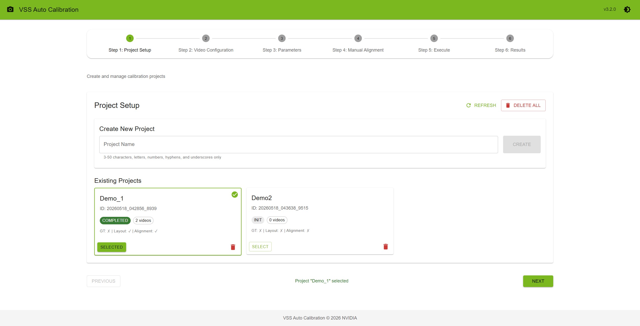
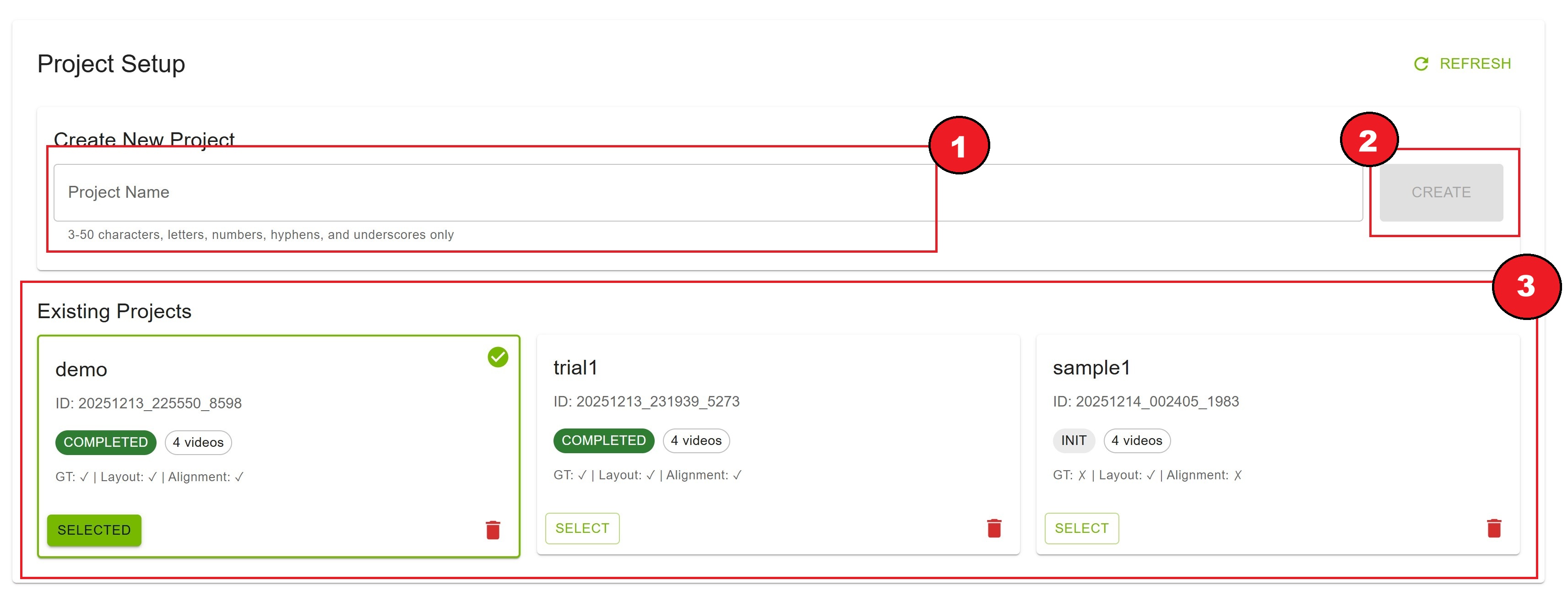
Creating a New Project#
Enter a project name in the text field
Requirements: 3-50 characters
Example:
warehouse_cam_2024,parking_lot_north
Click the “Create” button
The new project appears in the “Existing Projects” list below
Project Name Validation
✓ Valid:
warehouse_calibration,site_01,parking-lot-A✗ Invalid:
ab(too short)
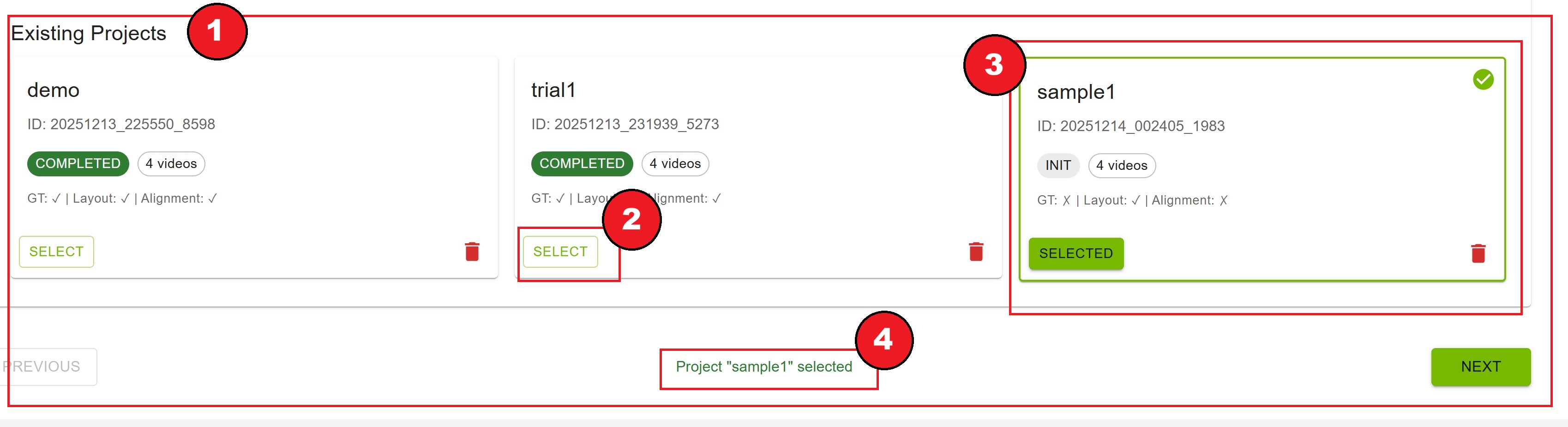
Selecting a Project#
Browse the list of existing projects
Click the “Select” button on the desired project card
The selected project is highlighted with a green border and checkmark
Project information is displayed at the bottom: “Project ‘name’ selected”
Project Card Information
Each project card displays:
Project Name: The name you assigned
Project ID: Unique identifier (UUID)
Project State: Current status badge
INIT(gray): Initial state, files not yet uploadedREADY(green): Ready for calibrationRUNNING(orange): Calibration in progressCOMPLETED(green): Calibration finished successfullyERROR(red): Calibration failed
Video Count: Number of uploaded video files
File Status: Checkmarks for uploaded files
GT (Ground Truth): ✓ or ✗
Layout: ✓ or ✗
Alignment: ✓ or ✗
Managing Projects#
Refreshing the Project List
Click the “Refresh” button in the top-right corner to reload the project list from the server.
Deleting a Project
Click the trash icon (🗑️) on the project card
Confirm deletion in the dialog that appears
The project and all associated data are permanently deleted
Deleting All Projects
In the Project Setup header (next to Refresh), click Delete all
Confirm in the Delete all projects? dialog
Every removable project is permanently deleted; the project list reloads afterward
The button is disabled when there are no projects. Projects with calibration running or RTSP capture in progress are skipped and not removed.
Warning
Deleting a project (or using Delete all) cannot be undone. Export any important calibration results before deletion.
Project States Explained
INIT: Project created, awaiting file uploads
READY: All required files uploaded and verified
RUNNING: Calibration pipeline is executing
COMPLETED: Calibration finished, results available
ERROR: Calibration failed, check logs or re-upload files
Step 2: Video Configuration#
Upload camera videos, layout image, ground truth data, and optional alignment file.
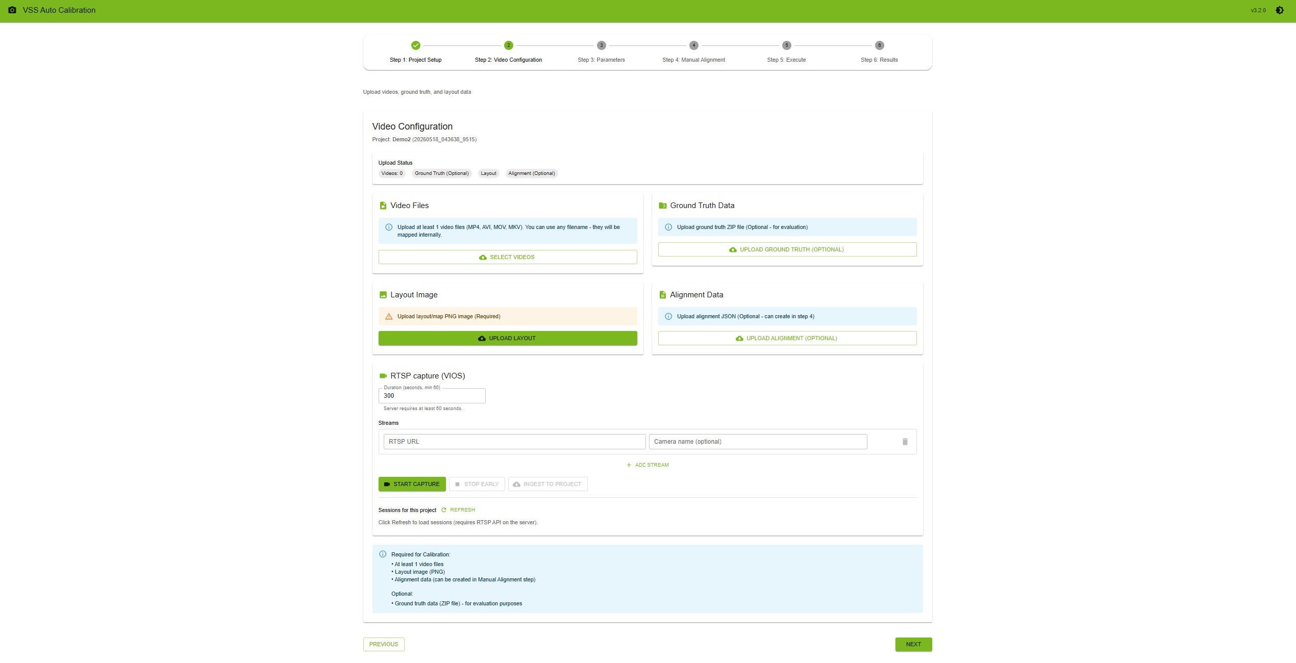
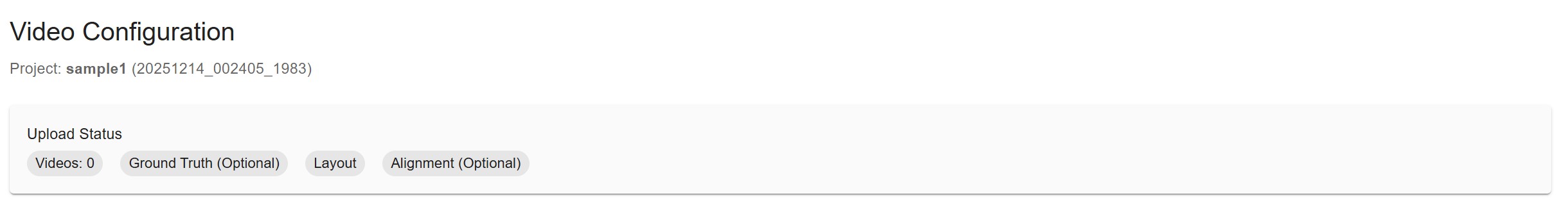
Upload Status Overview#
At the top of the page, you’ll see a status summary showing:
Videos: Count of uploaded videos (minimum 1 required)
Ground Truth (Optional): Upload status
Layout: Upload status (required)
Alignment (Optional): Upload status
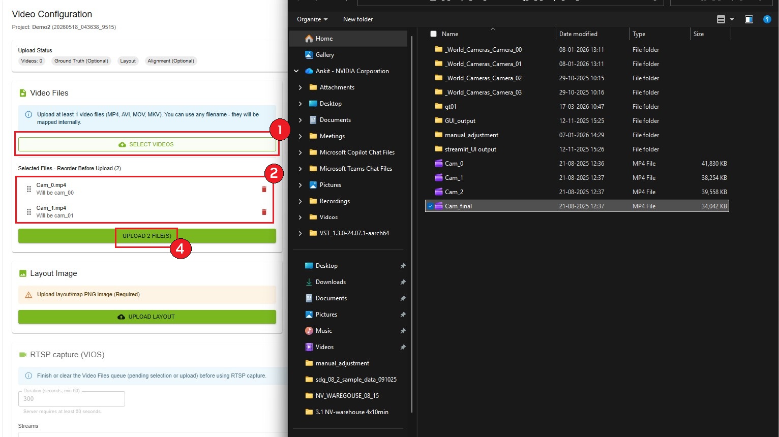
Uploading Video Files#
Requirements
Minimum: 1 video file
Formats: MP4
Required Video Resolution: 1920 x 1080
Provide camera inputs using either file upload or RTSP capture (one camera for single-camera calibration, two or more for multi-camera). RTSP capture is available only when VIOS is configured on the Auto Calibration server; otherwise use file upload. The UI does not allow an active file-upload queue and RTSP capture at the same time; remove file-uploaded clips before switching to RTSP, and vice versa.
Option A: Upload video files
Click Select Videos to choose video files from your computer (MP4)
Selected videos appear in a list where you can reorder them by dragging
Reorder videos to match your desired camera order (for example
cam_00,cam_01, etc.)—maintain order of overlapping field of view (FOV)Click Upload N File(s) to upload all selected videos
Wait for the upload progress bar to complete
Managing Video Files
View List: All selected or uploaded videos are listed with their filenames
Reorder: Drag and drop videos to change their order before uploading
Delete Video: Click the trash icon (🗑️) next to a video to remove it
Re-upload: Delete and upload again if needed
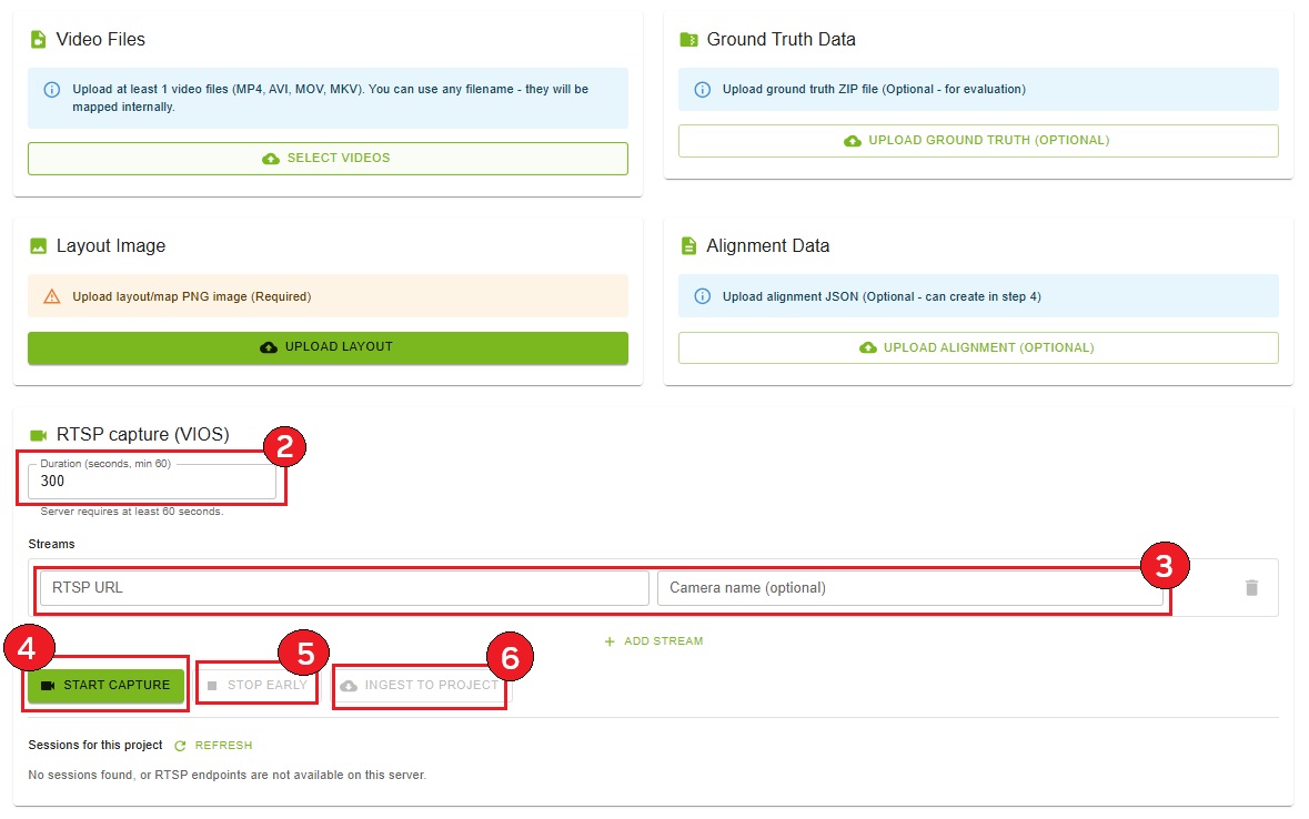
Option B: RTSP capture (VIOS)
(Shown only when the Auto Calibration service exposes RTSP capture; VIOS is configured on the server side.)
Finish or clear any pending Video Files selection or upload before starting RTSP; if the project already has clips from file upload, remove them under Video Files first
In the RTSP capture (VIOS) card, set Duration (seconds) (minimum 60 seconds, per server requirement)
Under Streams, enter all RTSP URLs for the project before capturing. Use Add stream for additional cameras. Optionally set Camera name
Click Start capture once for the full stream list (all cameras record together). Do not add streams later or run separate captures at different times—that breaks time synchronization
Wait for the status chip and progress bar (STARTING → RECORDING → STOPPING / INGESTING as applicable)
Optionally click Stop early after at least 60 seconds of active recording
When the session reaches COMPLETED or CANCELLED, click Ingest to project to add captured clips to the project’s video list
While RTSP capture or ingest is running, Video Files upload is disabled until the pipeline completes.
Note
RTSP streams must be time-synchronized: one Start capture with every stream configured together—no staggered captures or later ingest of additional streams. List each RTSP URL under Streams in order of overlapping FOV (first stream = first camera in the overlap chain).
Note
For VIOS pre-registered RTSP streams, use the source URL (for example, the NVStreamer URL if the stream originates from NVStreamer) rather than the VIOS-proxied URL.
Uploading Ground Truth Data#
Ground truth data is optional and used for calibration evaluation.
Requirements
Format: ZIP file
Content: Ground truth calibration data
Upload Process
Click “Upload Ground Truth (Optional)” button
Select your ZIP file
Wait for upload confirmation
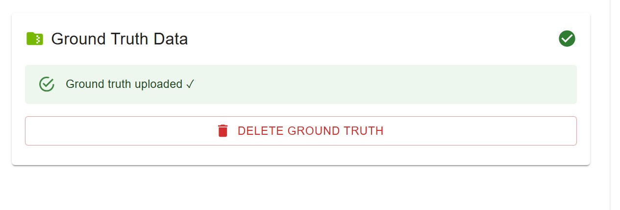
Status changes to “Ground truth uploaded ✓”
Deleting Ground Truth
If ground truth is already uploaded, the button changes to “Delete Ground Truth”. Click it to remove the file.
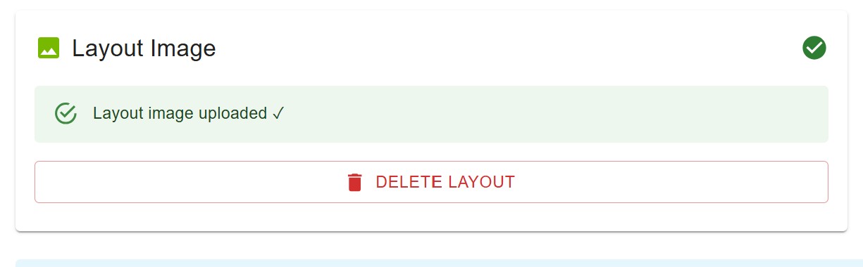
Uploading Layout Image#
The layout image is required and represents the top-down view or map of your surveillance area.
Requirements
Format: PNG
Content: Bird’s eye view map or layout diagram
Recommended: High resolution for better accuracy
Upload Process
Click “Upload Layout” button
Select your image file
Wait for upload confirmation
Status changes to “Layout image uploaded ✓”
Deleting Layout
If layout is already uploaded, the button changes to “Delete Layout”. Click it to remove the file.
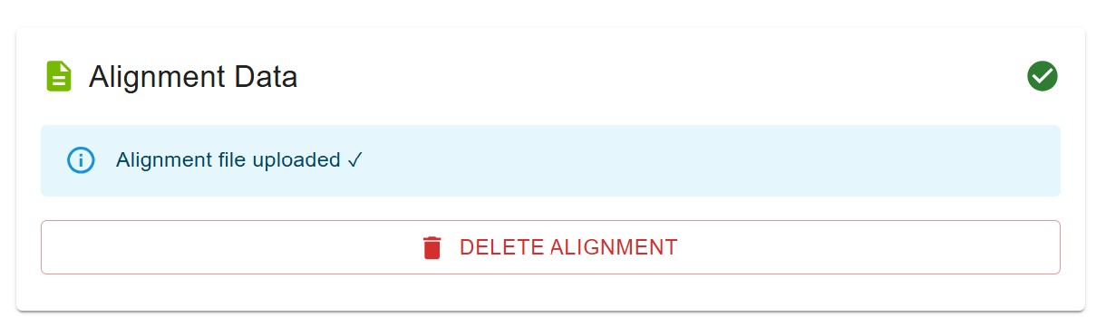
Uploading Alignment Data#
Alignment data is optional at this step. You can either upload a pre-existing alignment file here or create it interactively in Step 4.
Requirements
Format: JSON file
Content: Alignment point data (4+ point sets)
Upload Process
Click “Upload Alignment (Optional)” button
Select your JSON file
Wait for upload confirmation
Status changes to “Alignment file uploaded ✓”
Deleting Alignment
If alignment is already uploaded, the button changes to “Delete Alignment”. Click it to remove the file.
Requirements Note#
At the bottom of the page, you’ll see a summary of requirements:
Required for Calibration:
At least 1 video file (2 or more for multi-camera calibration)
Layout image (PNG)
Alignment data (can be created in Manual Alignment step)
Optional:
Ground truth data (ZIP file) - for evaluation purposes
Note
You can proceed to the next step even if ground truth and alignment are not uploaded. Alignment can be created interactively in Step 4.
Step 3: Parameters#
Configure camera parameters, draw per-camera or global ROIs and tripwires, optionally export image-mode JSON, and set focal lengths.
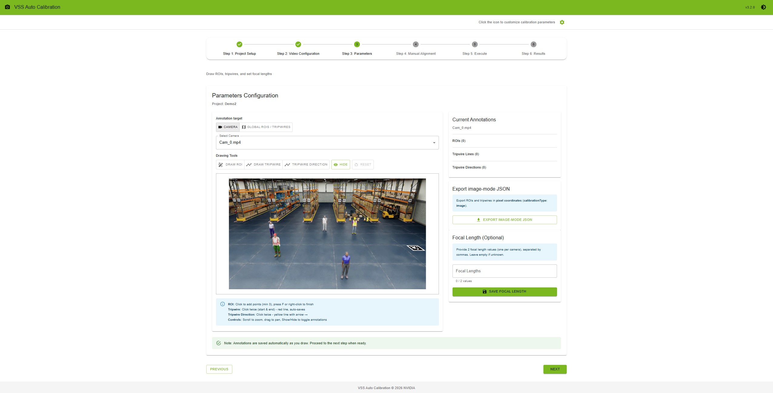
Interface Layout#
The Parameters step is divided into two main sections:
Left Panel (Main Canvas)
Annotation target toggle: Camera or Global ROIs / tripwires
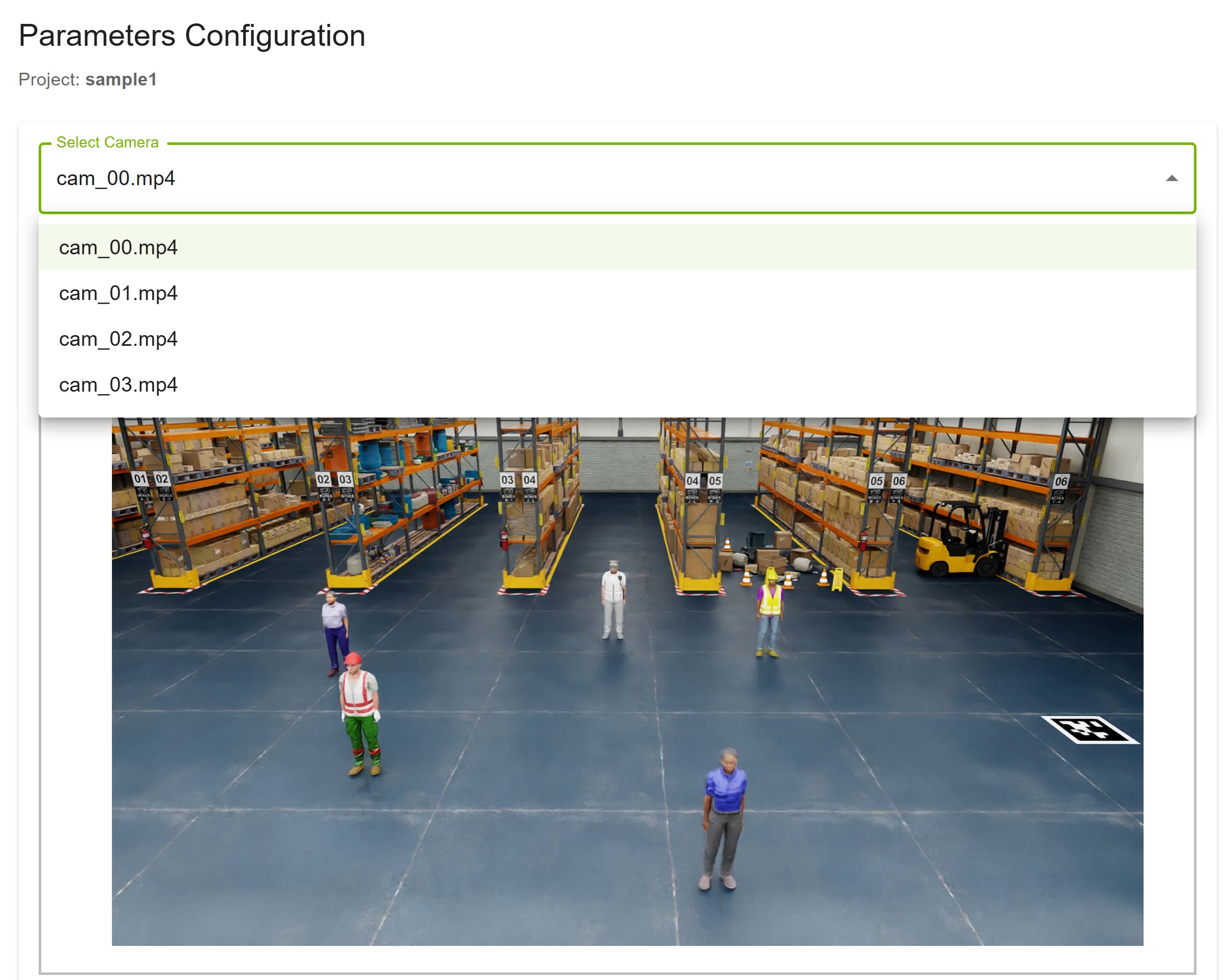
Camera selection dropdown (when Camera is selected)
Drawing tools toolbar
Canvas: video frame (per-camera) or layout map (global)
Instructions and controls
Right Panel (Sidebar)
Current annotations list (per-camera or Global (layout map))
ROI, tripwire line, and tripwire direction counts
Export image-mode JSON — download ROIs and tripwires in pixel coordinates
Focal length configuration (optional)
Annotation Target#
Choose Camera or Global ROIs / tripwires at the top of the left panel before drawing.
Camera (per-stream annotations)
Select Camera in the annotation target toggle
Choose a stream from the Select Camera dropdown
The first frame of the selected video loads on the canvas
Switch between cameras to draw ROIs, tripwire lines, and tripwire directions on each one
Global ROIs / tripwires (layout-map annotations)
Upload a layout image in Step 2 (required for this mode)
Select Global ROIs / tripwires in the annotation target toggle (disabled until a layout is uploaded)
The layout map loads on the canvas instead of a video frame
Use the same drawing tools as for camera mode; global shapes are stored separately and listed as Global (layout map) in the right panel
Note
Global and per-camera annotations use the same tools and auto-save behavior.
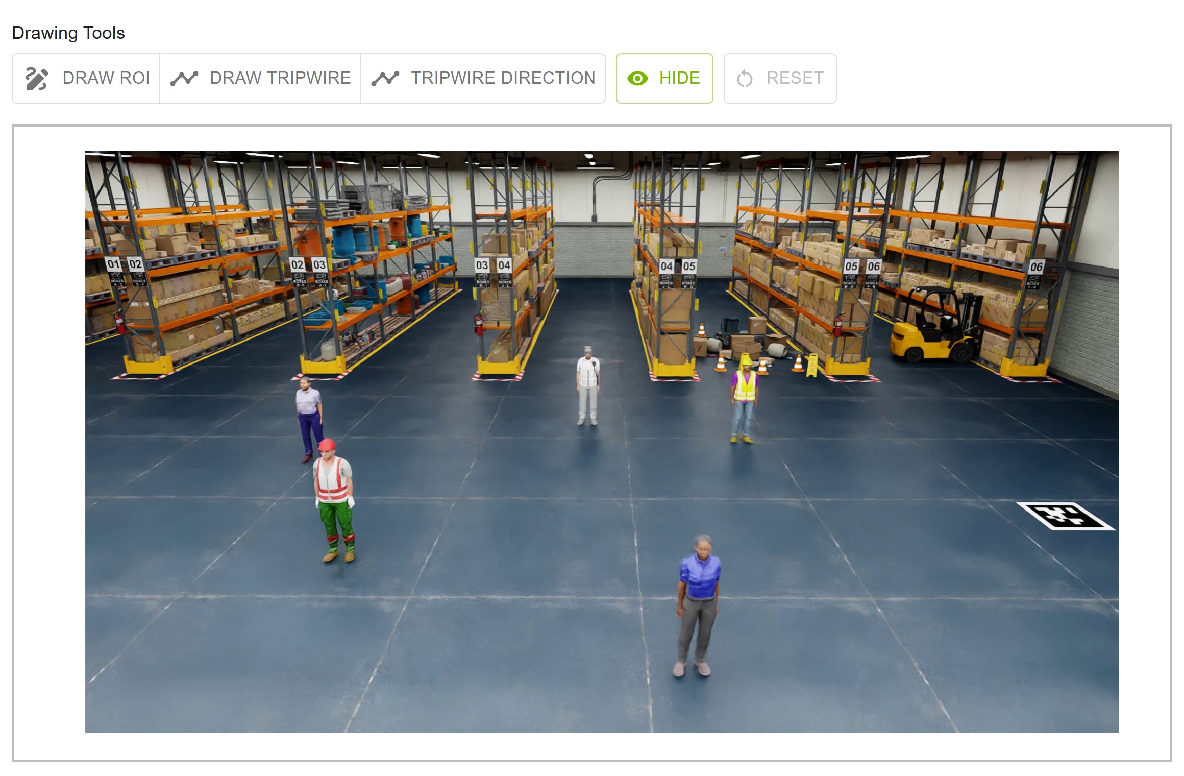
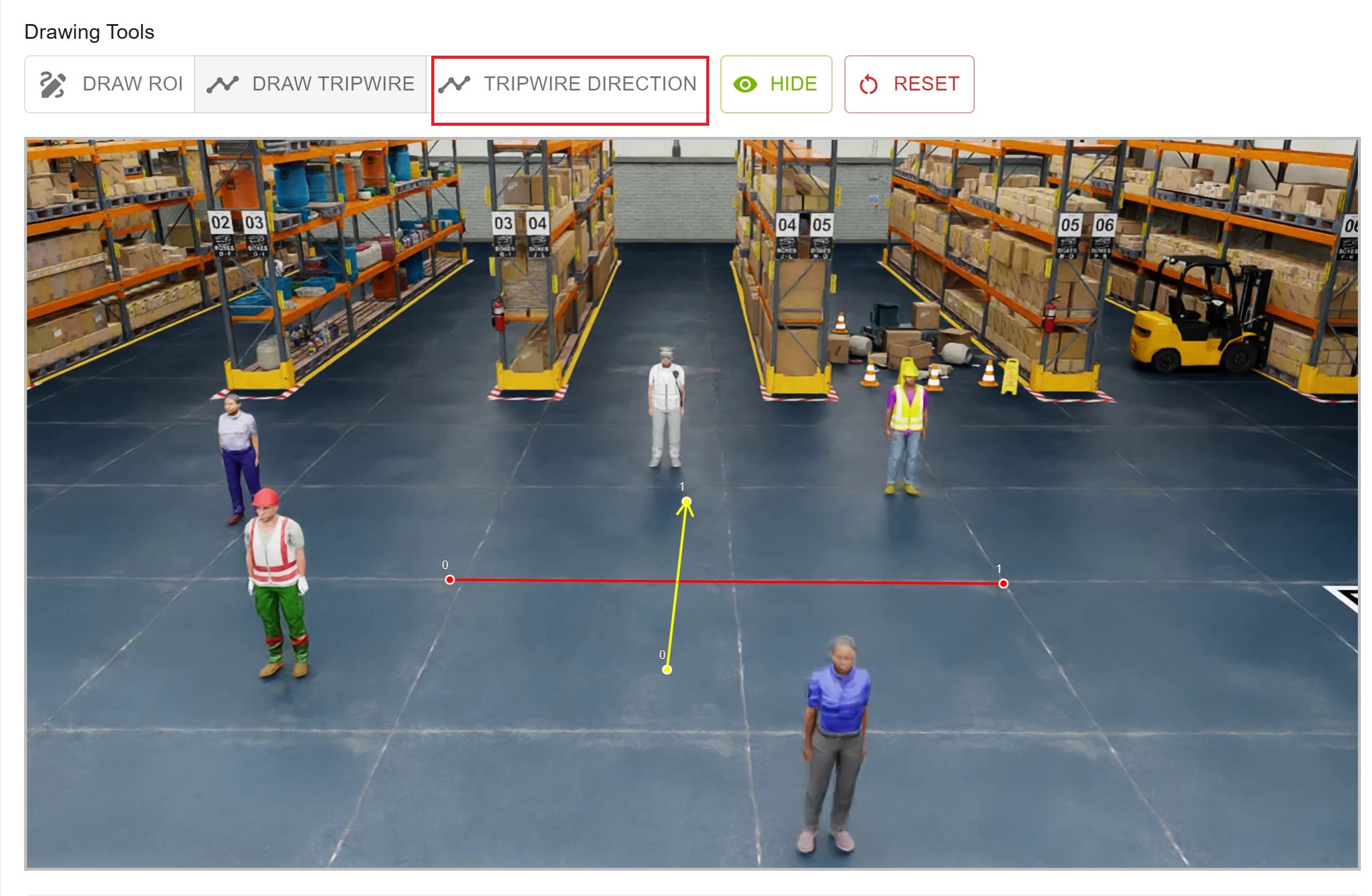
Drawing Tools#
Available Tools
Draw ROI: Create polygonal regions of interest
Draw Tripwire: Create tripwire lines for counting
Tripwire Direction: Create directional tripwires with arrows
Show/Hide: Toggle visibility of annotations
Reset: Clear all annotations for the active target (current camera or global layout map)
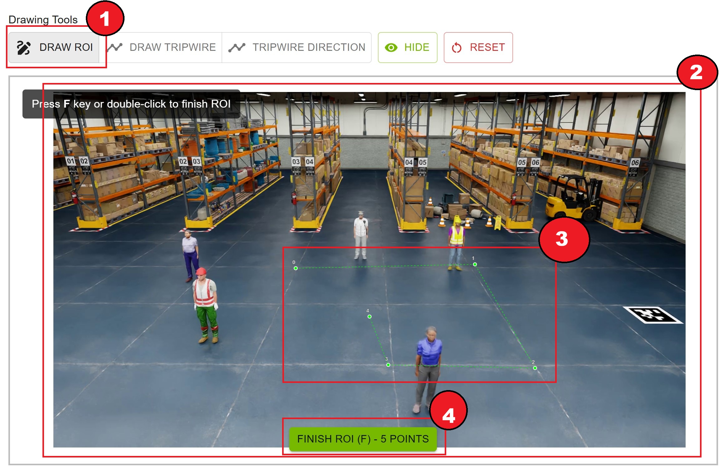
Drawing ROIs#
ROIs define areas of interest for detection and tracking.
How to Draw
Click the “Draw ROI” button (it becomes highlighted)
Click on the video frame to add points
Add at least 3 points to form a polygon
Finish the ROI by:
Pressing the
Fkey, orRight-clicking on the canvas
The ROI is automatically saved with a green color
ROI Features
Color: Green (#00ff00)
Minimum Points: 3
Maximum Points: Unlimited
Auto-save: Saved immediately upon completion
Editing ROIs
Delete: Click the delete button next to the ROI in the right panel
Redraw: Delete the existing ROI and draw a new one
Drawing Tripwire Lines#
Tripwire lines are used for counting objects crossing a line.
How to Draw
Click the “Draw Tripwire” button
Click once to set the start point
Click again to set the end point
The tripwire line is automatically saved with a red color
Tripwire Line Features
Color: Red (#ff0000)
Points: Exactly 2 (start and end)
Auto-save: Saved immediately upon completion
Use Case: Bidirectional counting
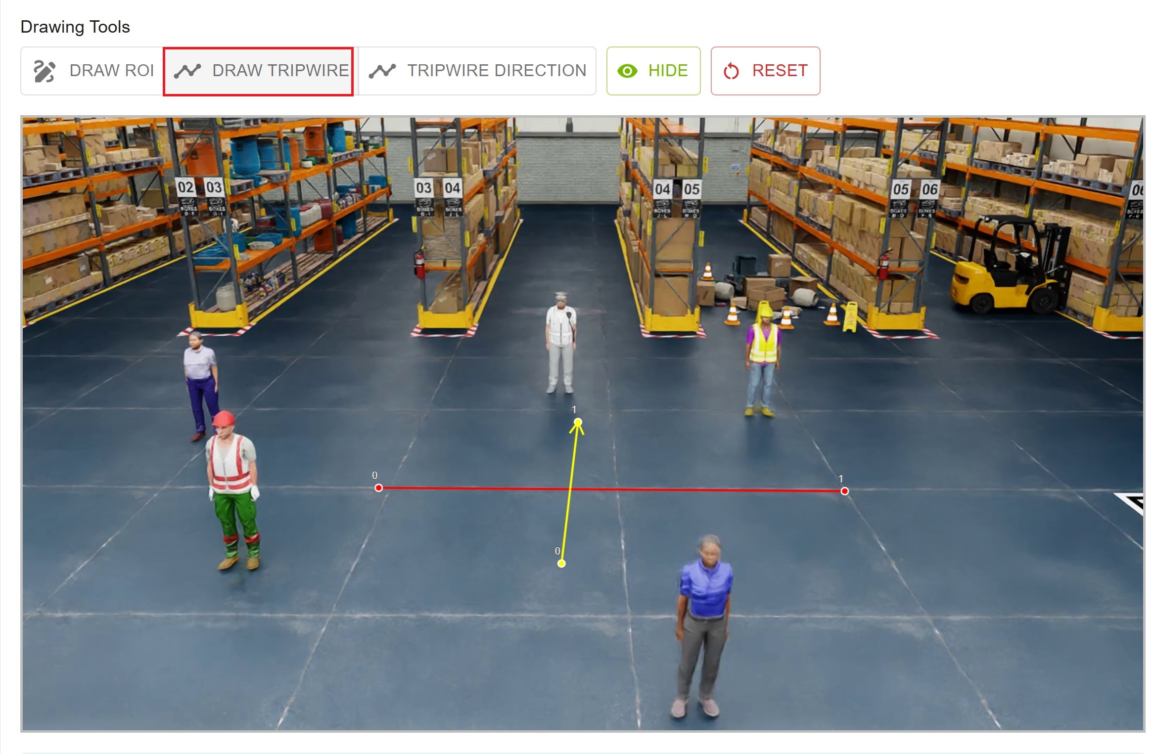
Drawing Tripwire Directions#
Tripwire directions are used for unidirectional counting with an arrow indicator.
How to Draw
Click the “Tripwire Direction” button
Click once to set the start point
Click again to set the end point (direction of arrow)
The tripwire direction is automatically saved with a yellow color and arrow
Tripwire Direction Features
Color: Yellow (#ffff00)
Arrow: Shows direction from start to end
Points: Exactly 2 (start and end)
Auto-save: Saved immediately upon completion
Use Case: Unidirectional counting (e.g., entry/exit)
Canvas Controls#
Zoom and Pan
Scroll Wheel: Zoom in/out on the canvas
Click + Drag: Pan around when zoomed in
Show/Hide Button: Toggle visibility of all annotations
Reset Button: Clear all annotations for the active annotation target
Visual Feedback
Drawing Mode: Active tool is highlighted in the toolbar
Cursor: Changes to crosshair when in drawing mode
Point Markers: Visible while drawing
Completed Annotations: Rendered with solid colors
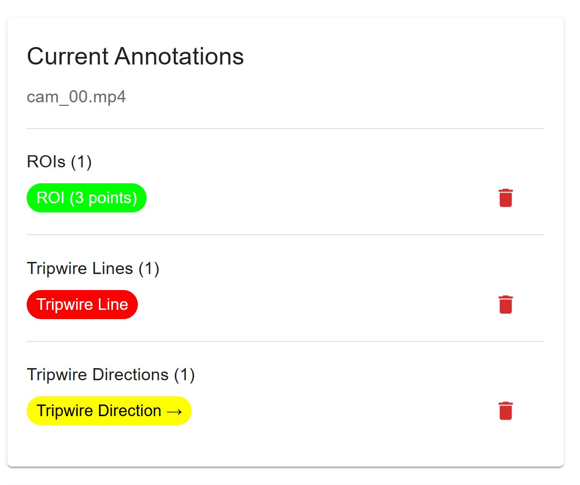
Annotation List (Right Panel)#
The right panel shows all annotations for the active target—the selected Camera or Global (layout map).
ROIs Section
Count of completed ROIs
Each ROI shown as a green chip with point count
Delete button for each ROI
Tripwire Lines Section
Count of completed tripwire lines
Each line shown as a red chip
Delete button for each line
Tripwire Directions Section
Count of completed tripwire directions
Each direction shown as a yellow chip with arrow
Delete button for each direction
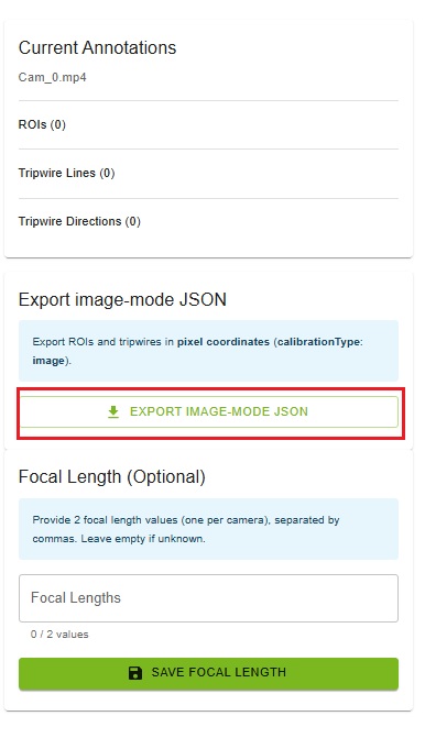
Export Image-Mode JSON#
Use this when you need ROIs and tripwires in pixel coordinates without running bundle adjustment.
How to Export
In the right panel, open the Export image-mode JSON card
Click Export image-mode JSON
The browser downloads
<project_name>_image_mode_exported.json
What Is Exported
ROIs and tripwires from all cameras plus any global layout annotations, in pixel space
calibrationTypeis image (same JSON shape as cartesian export)Does not require AMC calibration to have completed
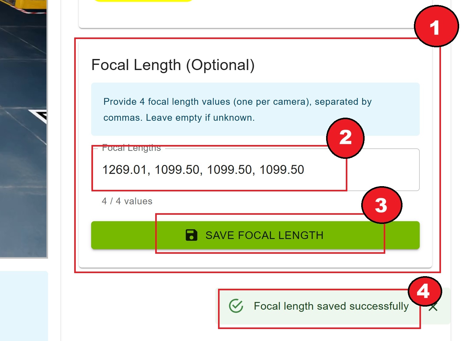
Focal Length Configuration#
Focal lengths are optional but can improve calibration accuracy.
Requirements
One value per camera
Comma-separated list
Positive numbers only
Count must match video count
How to Configure
In the right panel, find the “Focal Length (Optional)” card
Enter focal lengths separated by commas
Example:
1269.01, 1099.50, 1099.50, 1099.50
Click “Save Focal Length” button
Confirmation message appears
Clearing Focal Lengths
Delete all text from the input field
Click “Save Focal Length”
Focal lengths are cleared from the project
Auto-Save Feature#
All annotations (ROIs, tripwires, tripwire directions) are automatically saved to the server as you draw them.
No manual save required
Instant persistence
Per-camera and global storage
Survives page refresh
Note
The green success message “Note: Annotations are saved automatically as you draw. Proceed to the next step when ready.” confirms auto-save is active.
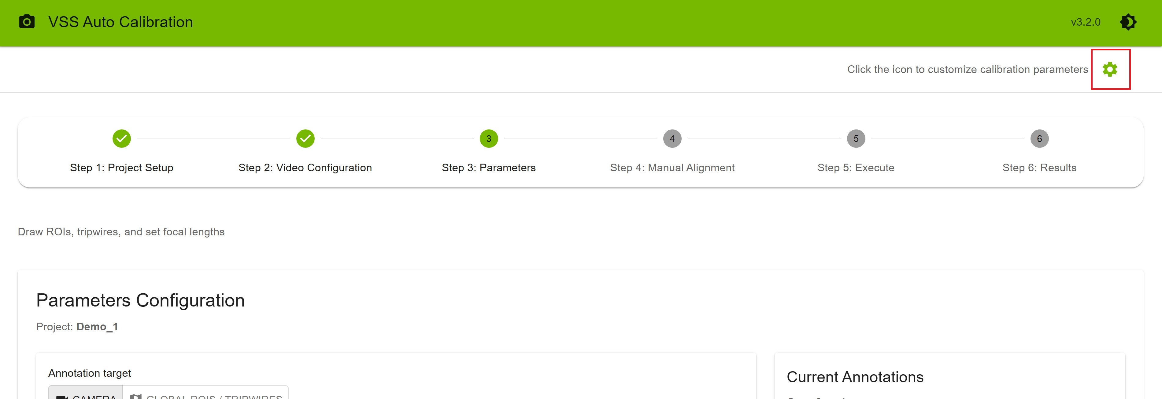
Configuring Settings#
On the Parameters step, you can customize calibration settings before running the pipeline. The settings icon in the top-right corner of the header is only visible on this step.
Accessing Settings
Click the settings icon in the top-right corner to access application settings.
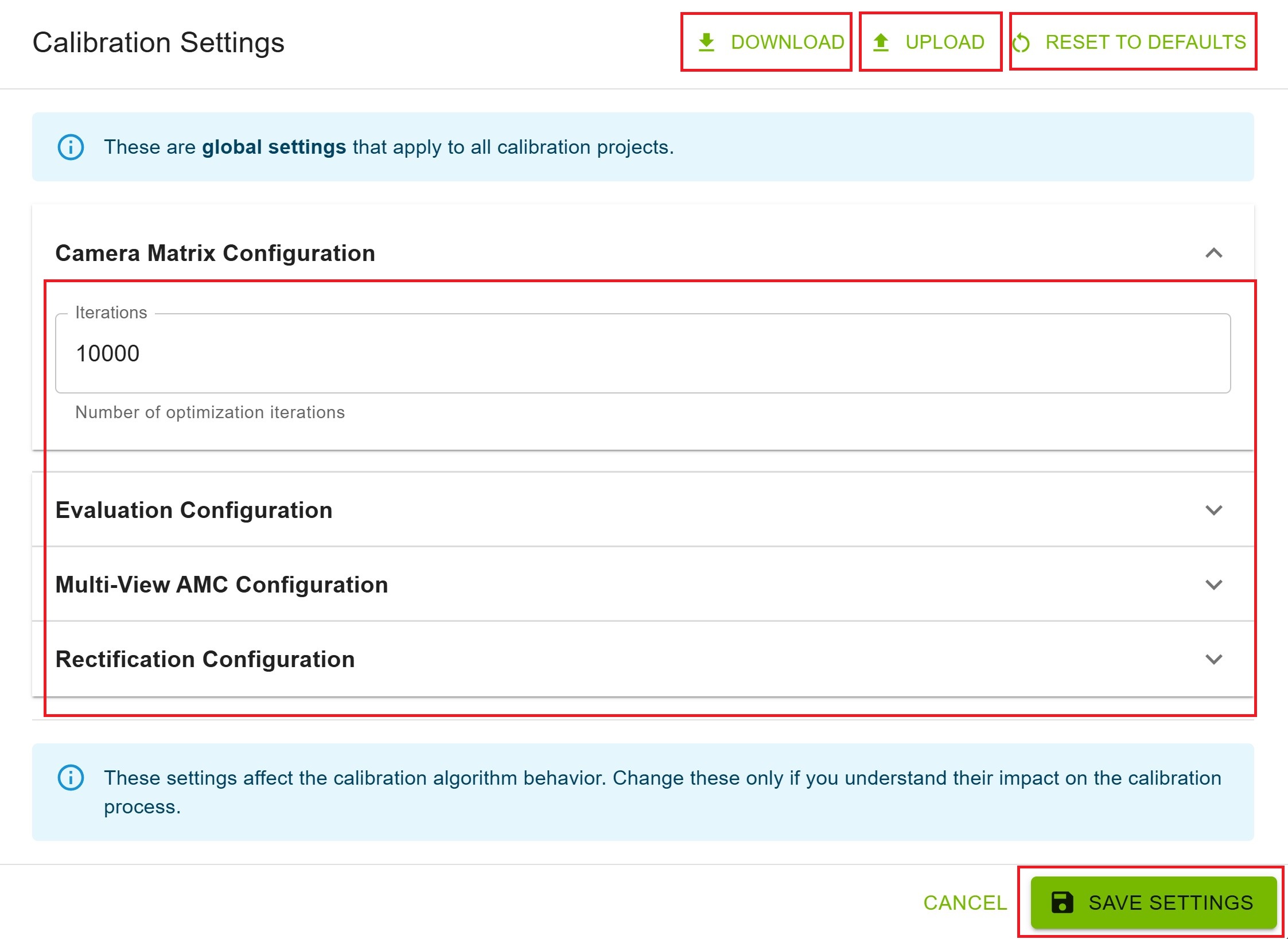
Configuration Options
You have two options to configure the settings:
Option 1: Upload - Upload a pre-configured settings file to apply all parameters at once
Option 2: Manual Configuration - Modify each parameter individually through the settings interface
Additional Actions
Download: Click the download button to export the current settings configuration to a file
Reset to Defaults: Click to restore all settings to their default values
Save Settings: Click “Save Settings” to save your changes
Warning
Do not attempt to change the settings while AMC calibration is running. Make all configuration changes before starting the calibration process (in Step 5: Execute).
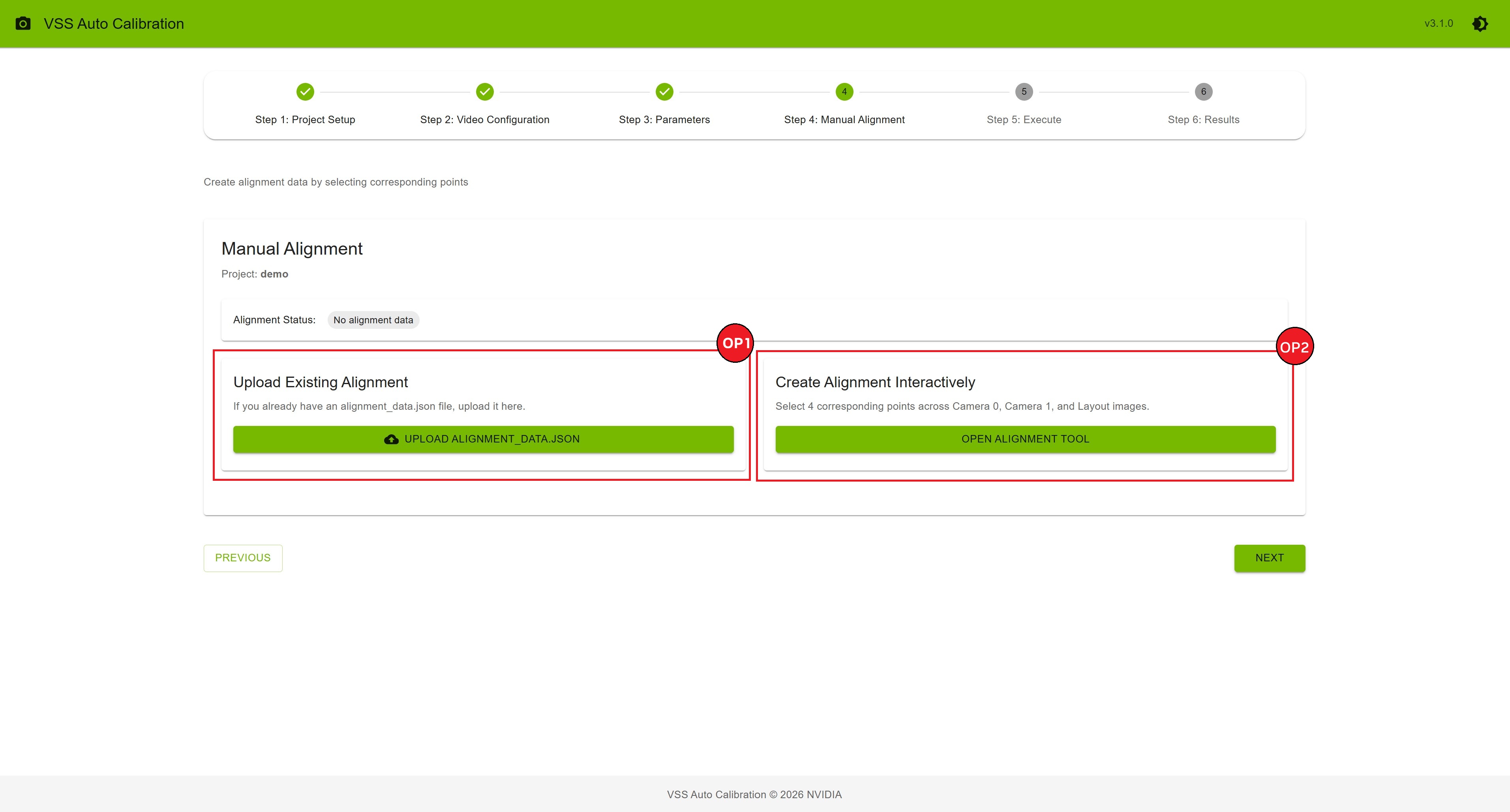
Step 4: Manual Alignment#
Two Options for Alignment#
Option 1: Upload Existing Alignment
If you already have an alignment_data.json file:
Click “Upload alignment_data.json” button
Select your JSON file from your computer
Wait for upload confirmation
Proceed to the next step
Option 2: Create Alignment Interactively
Create alignment data by selecting corresponding points:
Click “Open Alignment Tool” button
The interactive alignment interface opens
Follow the point selection process
Create alignment data by selecting corresponding points across camera views and the layout map.
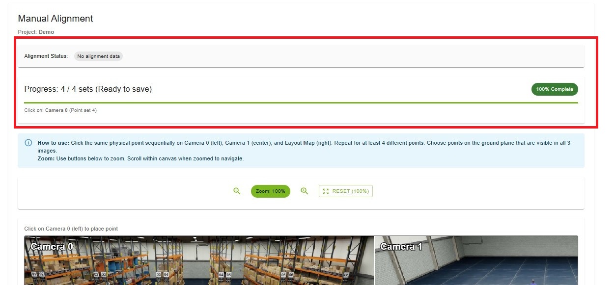
Alignment Status#
At the top of the page, you’ll see the current alignment status:
Green Badge: “Alignment data exists” - File already uploaded or created
Gray Badge: “No alignment data” - Need to upload or create alignment
Prerequisites Check#
Before creating alignment interactively, the system checks:
✓ At least 1 video uploaded
✓ Layout image uploaded
If prerequisites are not met, you’ll see a warning message directing you to Step 2.
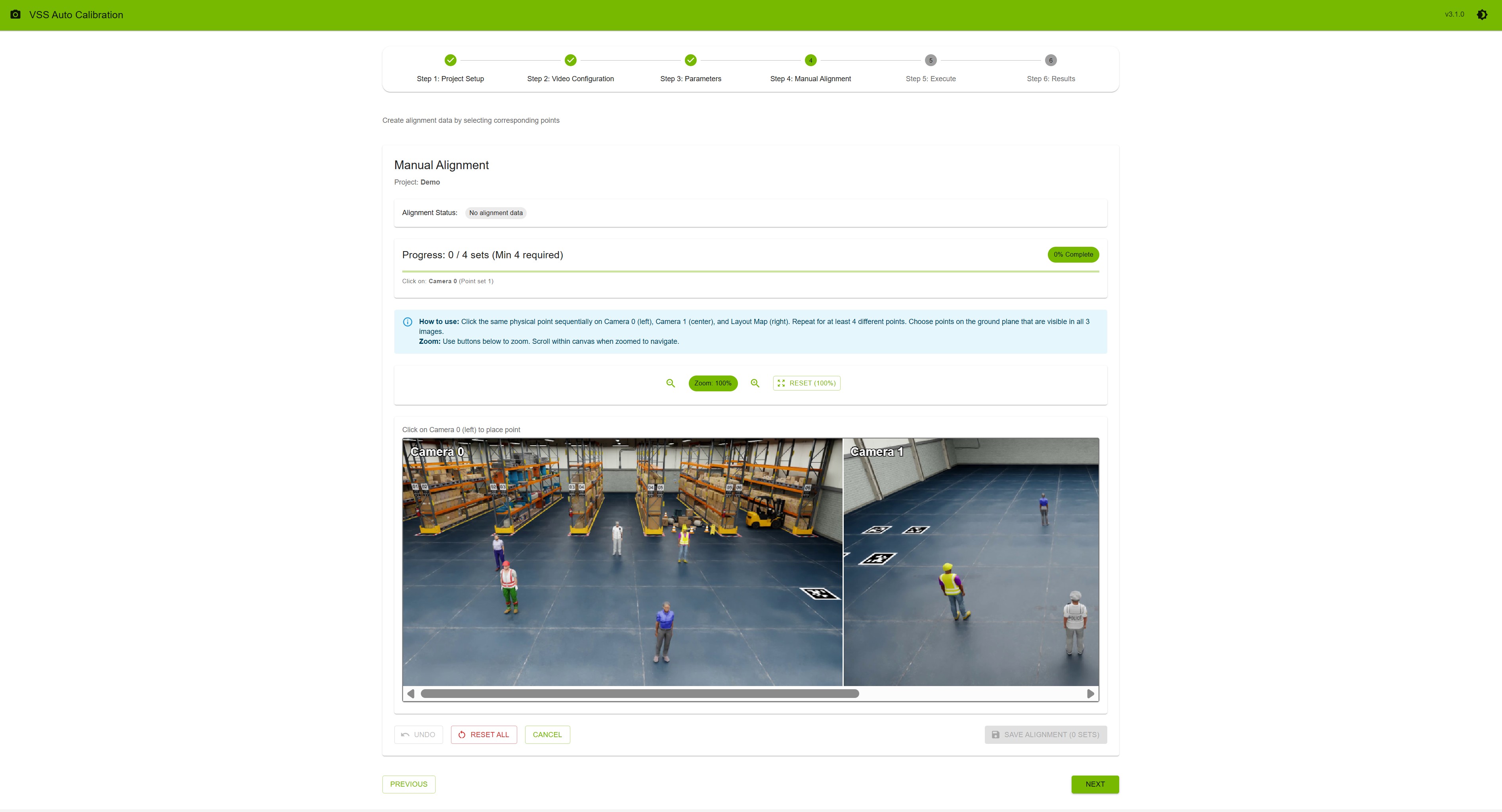
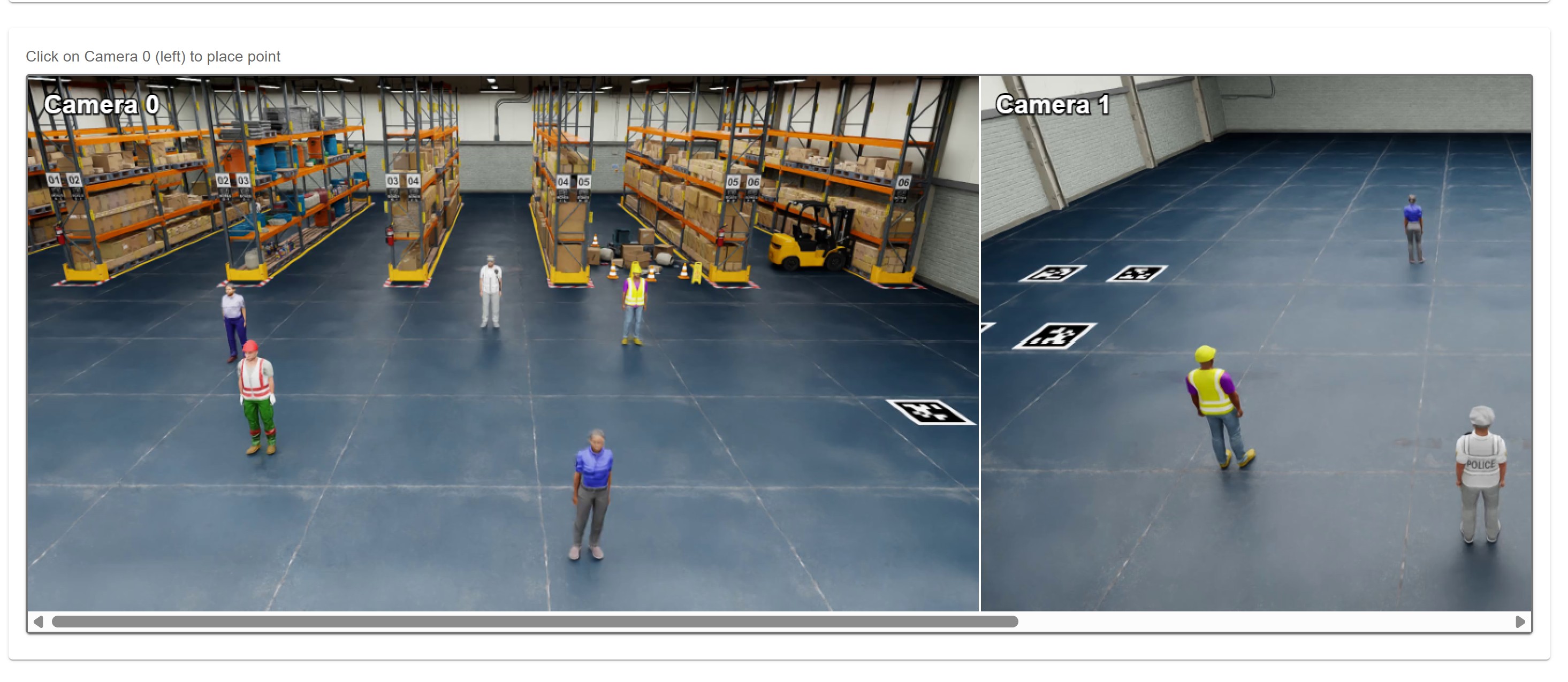
Interactive Alignment Tool#
Interface Overview
The alignment tool shows one concatenated canvas. The layout depends on how many videos are in the project:
Multi-camera (2 or more videos)
Left: Camera 0 (
cam_00.mp4)Center: Camera 1 (
cam_01.mp4)Right: Layout map (BEV — bird’s eye view)
Single-camera (1 video)
Left: Camera (
cam_00.mp4)Right: Layout map (BEV)
Progress Indicator
At the top, you’ll see:
Progress Bar: Visual progress (0-100%)
Completion Status: “X / Y sets (Min 4 required)” or “(Ready to save)”
Current Action: Prompt shows the next panel to click—for example Camera 0, Camera 1, Layout Map, or Camera (single-camera)
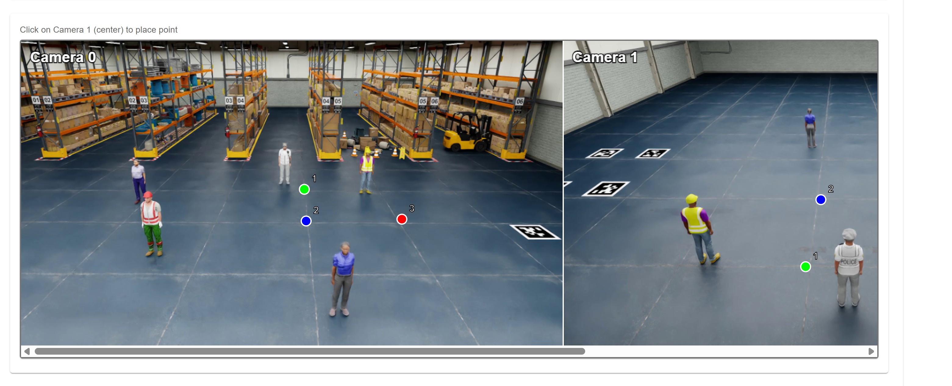
Point Selection Process#
Multi-camera (3 clicks per point set)
Select Point on Camera 0
Click on a distinct feature in Camera 0 (left section)
A colored circle with number “1” appears
System prompts: “Click on: Camera 1”
Select Corresponding Point on Camera 1
Click on the same physical location in Camera 1 (center section)
System prompts: “Click on: Layout Map”
Select Corresponding Point on Layout
Click on the same physical location on the layout map (right section)
Point Set 1 complete
Repeat for Additional Points
System automatically moves to the next point set
Repeat for at least 4 total point sets
Each set uses a different color (green, blue, red, yellow)
Single-camera (2 clicks per point set)
Select Point on Camera
Click on a distinct feature in the camera view (left section)
System prompts: “Click on: Layout Map”
Select Corresponding Point on Layout
Click on the same physical location on the layout map (right section)
Point Set 1 complete
Repeat for Additional Points
Repeat for at least 4 total point sets (same minimum as multi-camera)
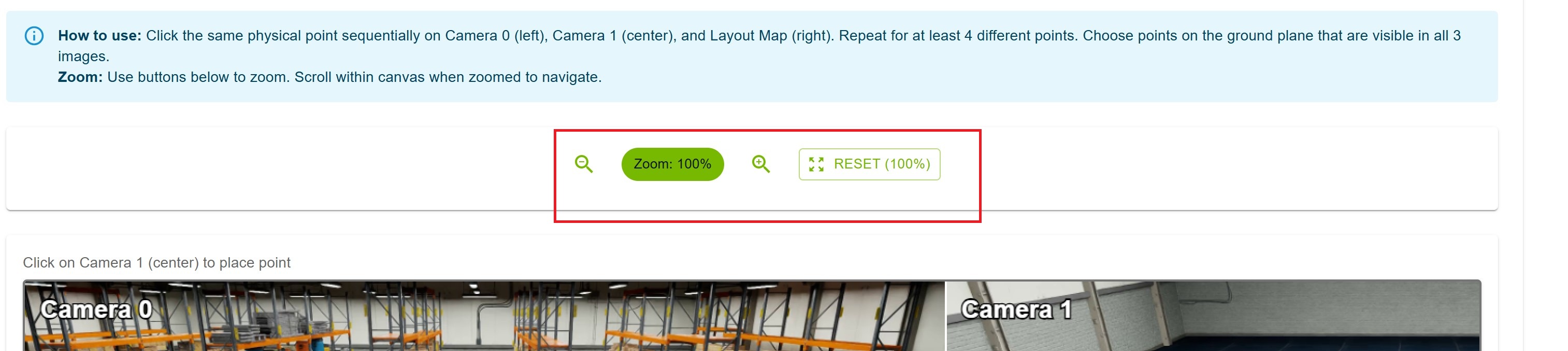
Point Selection Tips
Choose points on the ground plane
Select distinct features (corners, markings, poles)
Ensure each point is visible in every panel for that project (all cameras and the layout map, or camera + layout for single-camera)
Distribute points across different depths and locations
Avoid points on moving objects
Use zoom controls for precision
Zoom and Navigation#
Zoom Controls
Located above the canvas:
Zoom In (🔍+): Increase zoom level
Zoom Out (🔍-): Decrease zoom level
Reset (100%): Return to original zoom level
Current Zoom: Displayed as percentage (e.g., “Zoom: 150%”)
Navigation
Scroll Wheel: Zoom in/out on the canvas
Click + Drag: Pan around when zoomed in
Zoom Range: 50% to 300%
Point Set Management#
Undo Last Point
Click the “Undo” button to remove the most recently placed point.
Reset All Points
Click the “Reset All” button to clear all points and start over.
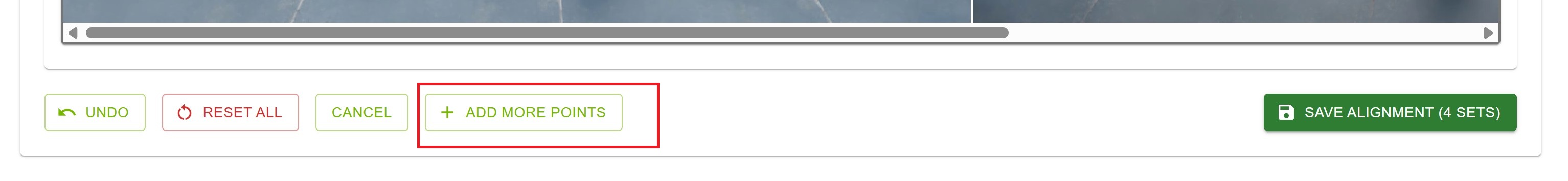
Add More Points
After completing 4 point sets, you can add more for improved accuracy:
Click “Add More Points” button
A new empty point set is added
Continue selecting points as before
Saving Alignment Data#
Requirements
Minimum 4 complete point sets
Multi-camera: each set must include Camera 0, Camera 1, and layout map points
Single-camera: each set must include camera and layout map points (2 points per set)
Save Process
Complete at least 4 point sets
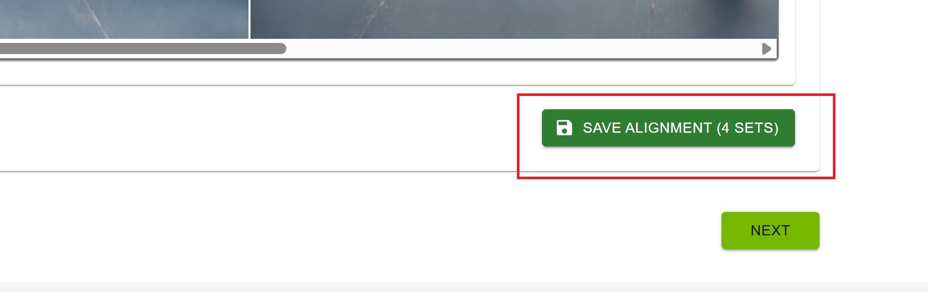
The “Save Alignment” button becomes enabled
Button shows: “Save Alignment (X sets)” where X is the count
Click “Save Alignment (X sets)”
System generates and uploads the alignment JSON file
Success message appears
Alignment tool closes automatically
Cancel Creation
Click the “Cancel” button to exit the alignment tool without saving.
Alignment Data Format#
The generated alignment data is a JSON array. Each outer element is one point set; coordinates are in pixel space of the original images.
Multi-camera — three [x, y] pairs per set (camera 0, camera 1, layout):
[
  [[x0_cam0, y0_cam0], [x0_cam1, y0_cam1], [x0_layout, y0_layout]],
  [[x1_cam0, y1_cam0], [x1_cam1, y1_cam1], [x1_layout, y1_layout]],
  ...
]
Single-camera — two [x, y] pairs per set (camera, layout):
[
  [[x0_cam, y0_cam], [x0_layout, y0_layout]],
  [[x1_cam, y1_cam], [x1_layout, y1_layout]],
  ...
]
Deleting Alignment Data#
If alignment data already exists and you want to recreate it:
The interface shows: “Alignment data already exists for this project”
Click “Delete Alignment Data” button
Confirm deletion
Create new alignment using either upload or interactive method
Warning
Deleting alignment data cannot be undone. You’ll need to recreate or re-upload it.
Best Practices#
Point Selection Strategy
Minimum 4 points: Required for calibration
Recommended 6-8 points: Better accuracy and robustness
Point Distribution
Spread points across the entire area
Include points at different depths (near and far)
Cover all quadrants of the layout
Avoid clustering points in one area
Point Quality
Use sharp, distinct features
Avoid ambiguous or blurry areas
Prefer corners and intersections
Ensure good contrast
Common Mistakes to Avoid
✗ Selecting points on walls or elevated surfaces
✗ Choosing points only in the center
✗ Using points on moving objects
✗ Clicking too quickly without precision
✗ Forgetting to zoom in for accuracy
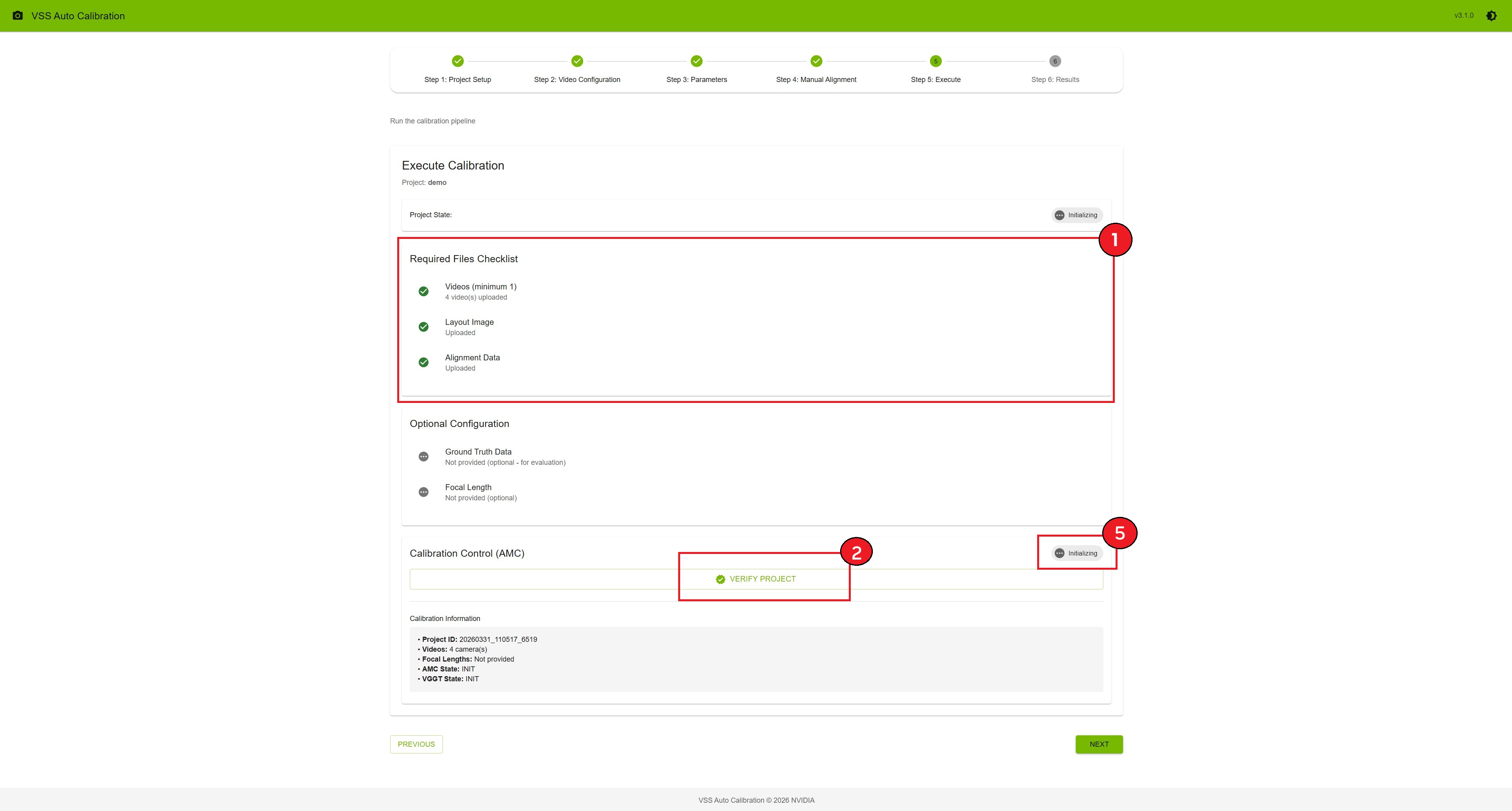
Step 5: Execute#
Verify project requirements and run the calibration pipeline with live monitoring.
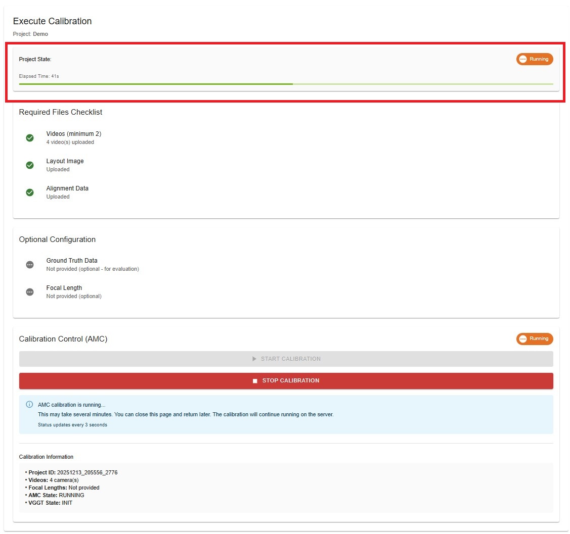
Project State Overview#
At the top of the page, you’ll see the current project state:
INIT (gray): Initial state
READY (blue): Ready to run calibration
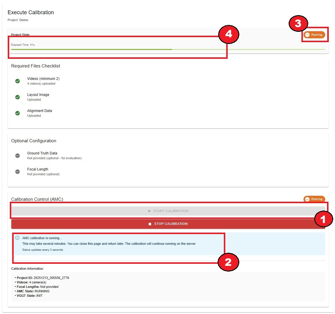
RUNNING (orange): Calibration in progress
COMPLETED (green): Calibration finished
ERROR (red): Calibration failed
When RUNNING, an elapsed time counter and progress bar are displayed.
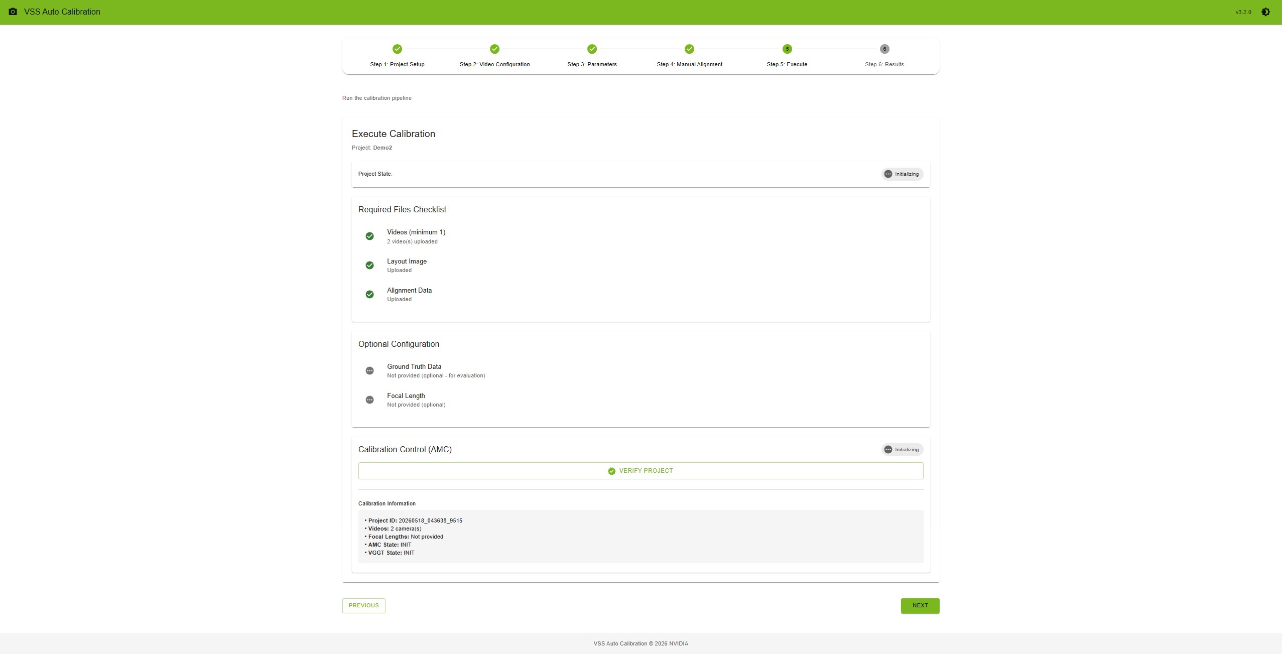
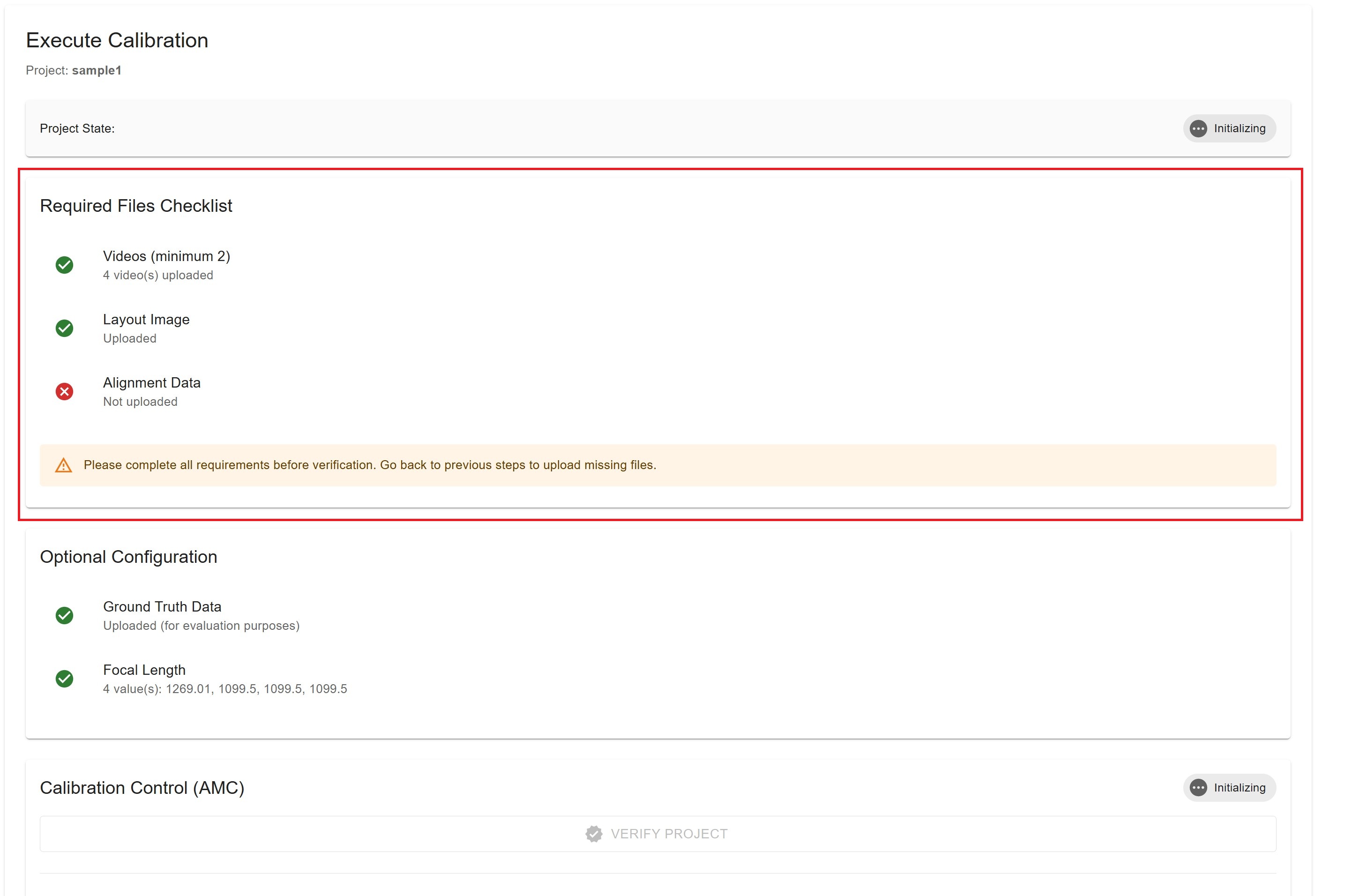
Requirements Checklist#
The system validates all required files before allowing calibration:
Required Files
✓ Videos (minimum 1): Shows count of uploaded videos
✓ Layout Image: Confirms layout is uploaded
✓ Alignment Data: Confirms alignment is uploaded or created
If any requirement is not met, you’ll see a warning message:
Warning
Please complete all requirements before verification. Go back to previous steps to upload missing files.
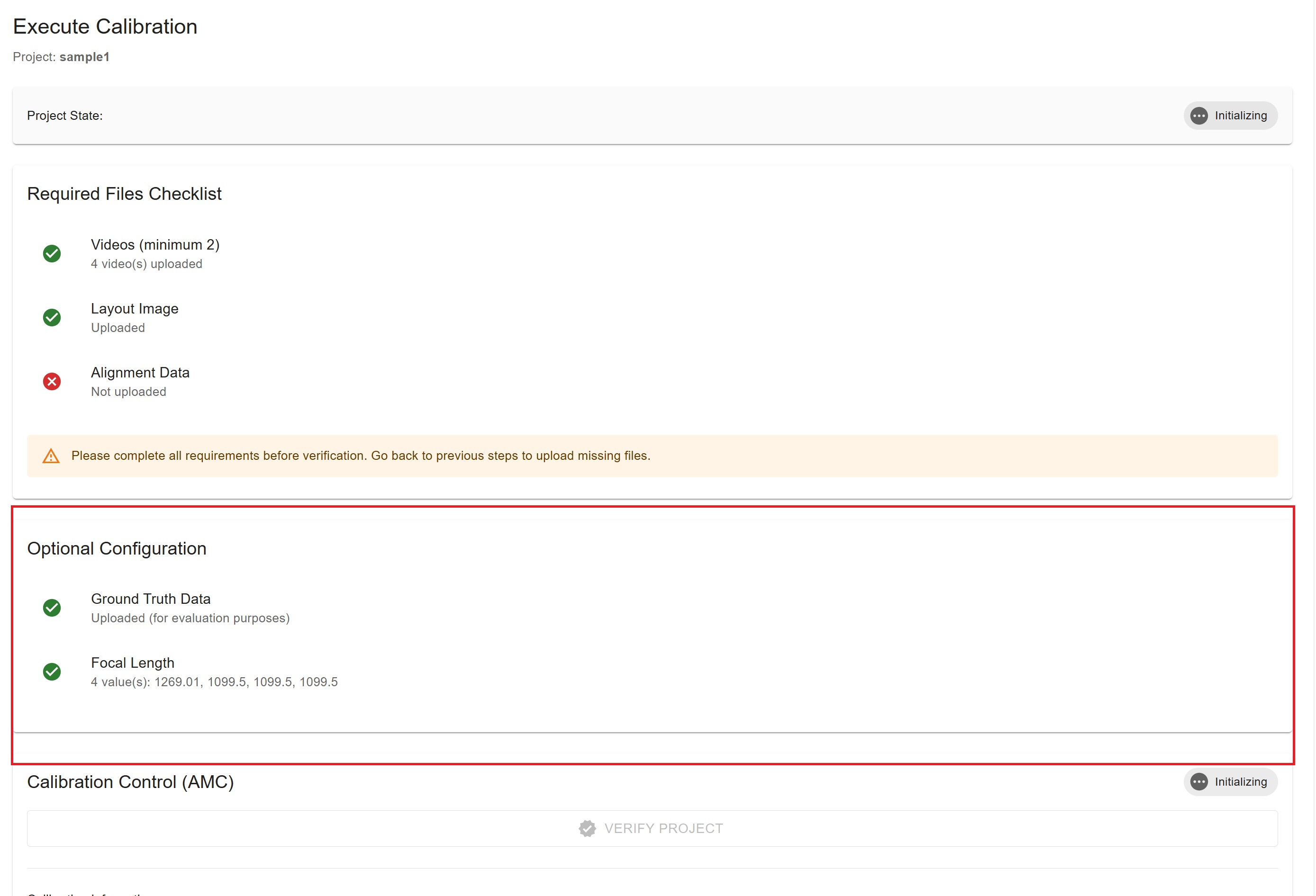
Optional Configuration#
The system also displays optional configuration status:
Ground Truth Data
✓ Uploaded (for evaluation purposes)
⊙ Not provided (optional - for evaluation)
Focal Length
✓ X value(s): Shows the focal length values
⊙ Not provided (optional)
Verification Process#
Before running calibration, you must verify the project.
How to Verify
Ensure all requirements are met (green checkmarks)
Click the “Verify Project” button
System validates all files and configurations
Success message appears: “Project verified successfully”
Project state changes to “READY”
“Start Calibration” button becomes enabled
Running AMC Calibration#
AMC (Auto Magic Calibration) is the primary calibration method.
How to Start
After verification, click “Start Calibration” button
Calibration pipeline begins immediately
Project state changes to “RUNNING”
Progress indicators appear
During Calibration
Elapsed Time: Updates every second
Progress Bar: Animated progress indicator
Status Message: “AMC calibration is running…”
Info Alert: “This may take several minutes. You can close this page and return later.”
AMC Live Logs: Real-time calibration logs displayed during execution
Auto-refresh: Status updates every 3 seconds
Stopping Calibration
If needed, you can stop the calibration:
Click “Stop Calibration” button (appears when RUNNING)
Calibration process terminates
Project state changes back to “READY”
Elapsed time resets
Warning
Stopping calibration will discard partial results. You’ll need to start over.
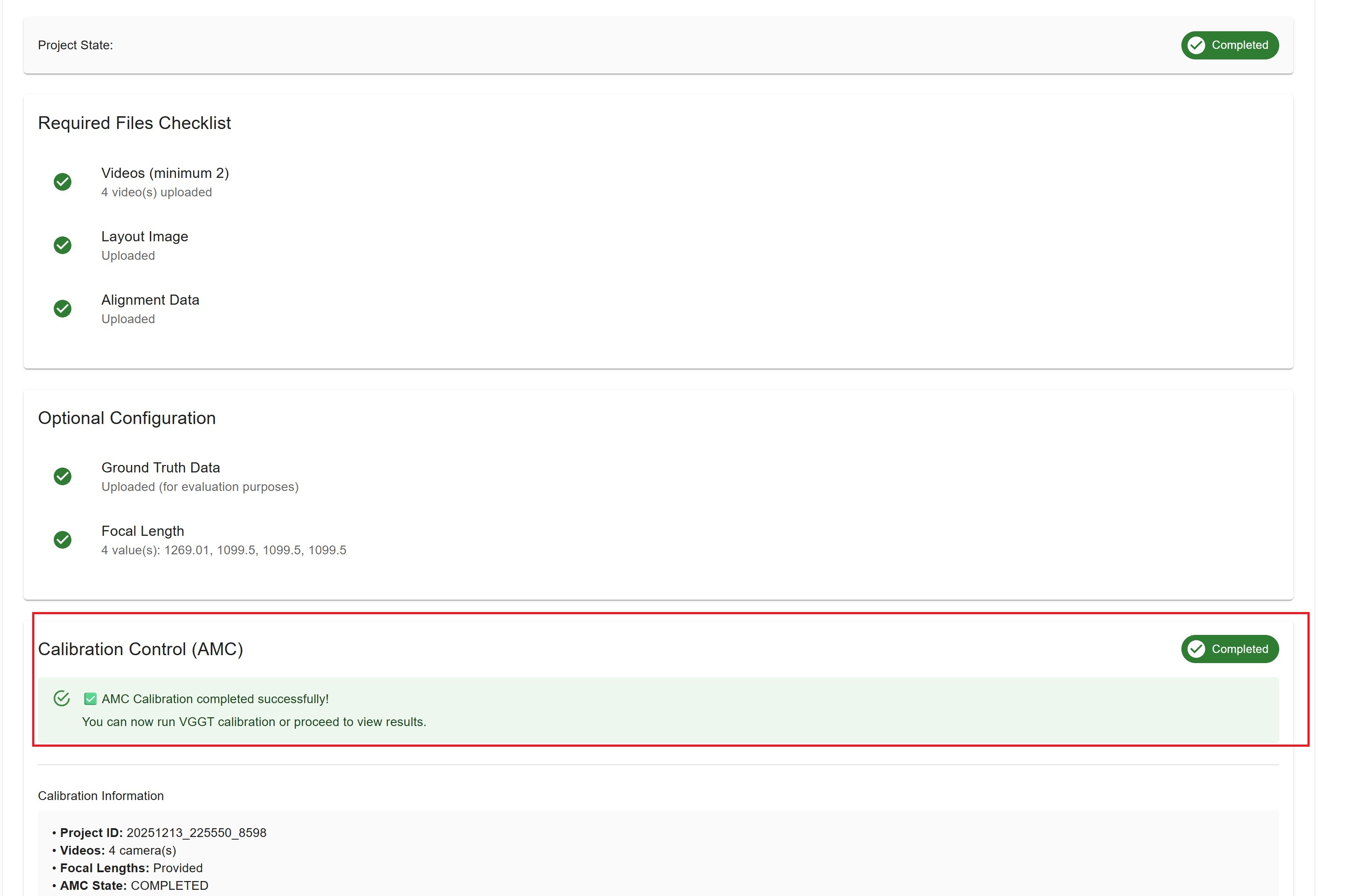
Calibration Completion#
When AMC calibration finishes successfully:
Success Alert: “✅ AMC Calibration completed successfully!”
Message: “You can now run VGGT calibration or proceed to view results.”
Project State: Changes to “COMPLETED”
AMC State: Shows “COMPLETED” badge
Next Steps: Proceed to Results, or run VGGT if installed (VGGT is optional and not required for a successful AMC-only run)
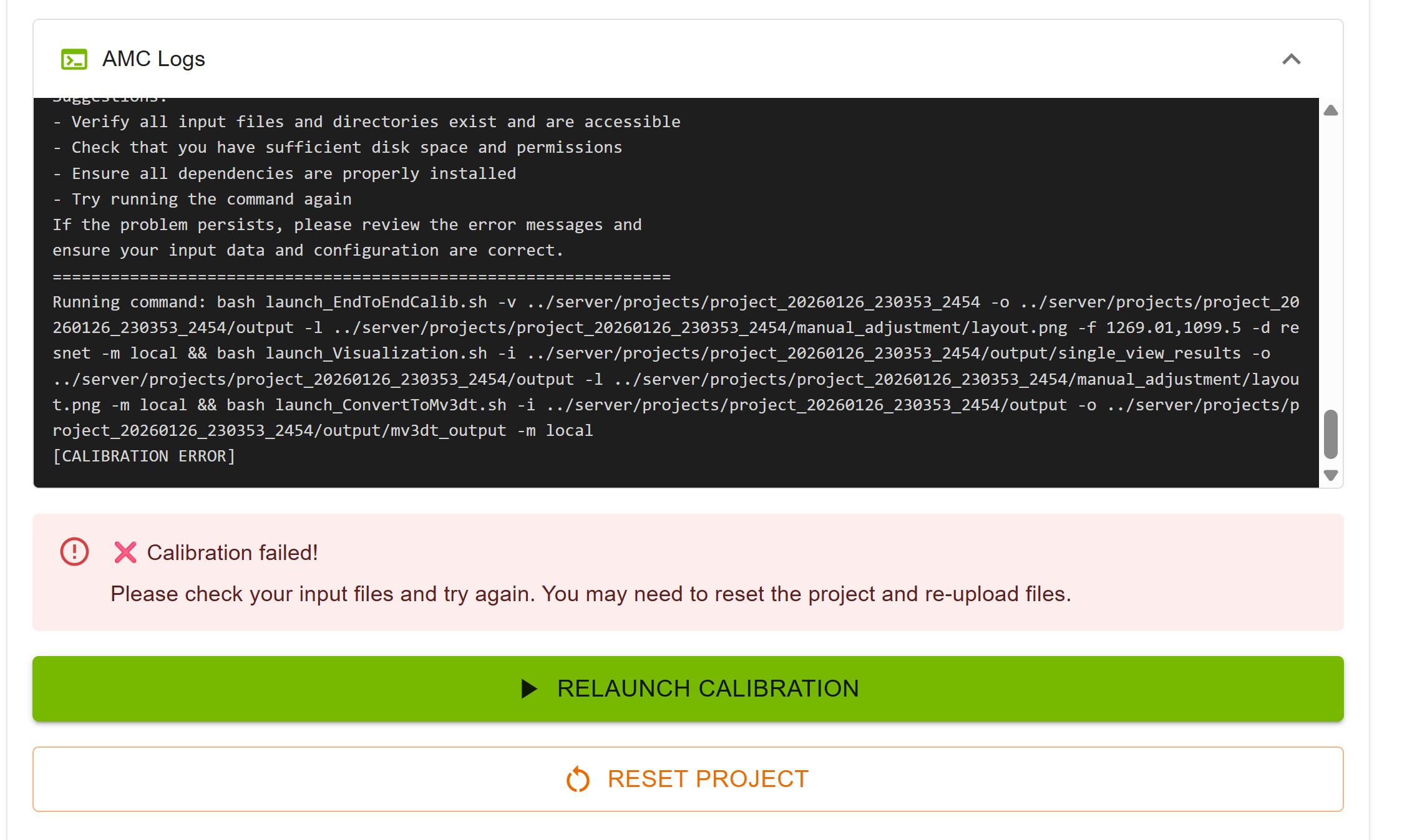
Calibration Failure#
If AMC calibration fails (for example during multi-view tracklet matching):
Error Alert: “❌ Calibration failed!”
Message: “Please check your input files and try again.”
Project State: May show ERROR while AMC State is ERROR
Reset Option: “Reset Project” button appears
If VGGT is installed and the required AMC output folders are already on disk (typically after single-view work including rectification), the Run VGGT Calibration control may still appear with VGGT state READY. A successful VGGT run sets the overall project to COMPLETED even when AMC did not finish—use Results to view VGGT calibration output.
How to Recover
Option 1: Relaunch Calibration
Click “Relaunch Calibration” button
The project is re-verified automatically
If verification passes, project state returns to “READY”
You can then start calibration again
Option 2: Reset Project
Click “Reset Project” button
Project state returns to “INIT”
Go back to previous steps
Check and re-upload files if needed
Try calibration again
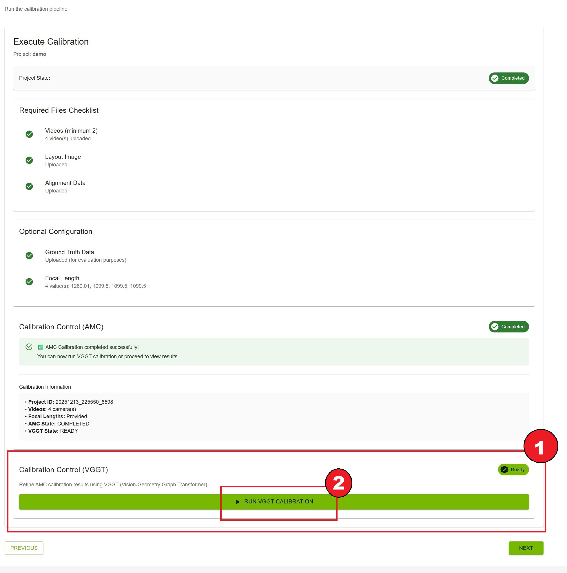
VGGT Calibration (Optional)#
VGGT (Vision-Geometry Graph Transformer) is an optional multi-camera calibration method. It is not tied to AMC reporting success: you can run VGGT after AMC has produced the needed on-disk outputs (in practice, once rectification is finished for your cameras), even if AMC later fails—for example at multi-view tracklet matching.
Note
VGGT requires VGGT support on the backend (model and dependencies installed). It is not offered for single-camera projects.
When Available
Multi-camera only (two or more videos)
Backend has VGGT installed and the UI shows the Calibration Control (VGGT) section
AMC does not need state COMPLETED; VGGT state READY is enough (the server enables this when required AMC output directories exist, including rectified single-view results)
AMC may still show ERROR if the classical pipeline failed after rectification—VGGT can remain runnable in that case
How to Run VGGT
After AMC has run far enough to create outputs (or after a failed AMC run that left outputs on disk), scroll to Calibration Control (VGGT)
Confirm VGGT state is READY
Click Run VGGT Calibration
Progress indicators and live logs appear (similar to AMC)
VGGT Features
Alternative Calibration Method: Alternative calibration using a vision-geometry graph transformer on rectified inputs
Duration: Typically 2–3 minutes
Independent of AMC success: Separate from the AMC Start Calibration run; can be started multiple times
Optional: You can use AMC-only results when AMC completes successfully; VGGT is an additional path when configured
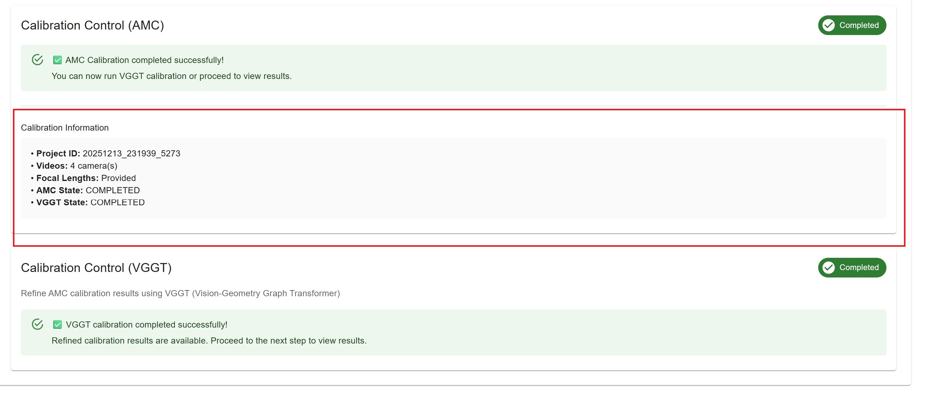
VGGT Completion
When VGGT finishes successfully:
Success Alert: “✅ VGGT calibration completed successfully!”
Message: “Refined calibration results are available.”
VGGT State: COMPLETED
Overall project state: COMPLETED (even if AMC previously failed)
Results: Open the Results step and use the VGGT tab for vggt calibration result;
Note
If AMC failed (for example during tracklet matching) but VGGT finishes successfully, treat the run as calibration completed successfully for the project: overall state is COMPLETED and you can proceed to Results using VGGT output. VGGT success indicates Calibration successfully completed.
VGGT Not Available
If VGGT is not installed on the backend:
Info Alert: “VGGT Calibration Not Available”
Message: “VGGT (Vision-Geometry Graph Transformer) is not installed on this system.”
Action: Rely on AMC results when AMC completes successfully, or fix AMC inputs and re-run AMC
Calibration Information#
At the bottom of the page, you’ll see a summary of calibration information:
Project ID: Unique identifier
Videos: Number of cameras
Focal Lengths: Provided or Not provided
AMC State: Current AMC state
VGGT State: Current VGGT state
Resetting the Project#
If you need to start over:
Click “Reset Project” button (available in ERROR state)
Confirm the action
Project state returns to “INIT”
All calibration results are cleared
Files remain uploaded
Warning
Resetting clears all calibration results. Export results before resetting if needed.
Best Practices#
Before Calibration
Double-check all uploaded files
Verify alignment points are accurate
Review ROIs and tripwires
Ensure stable network connection
After Calibration
Verify results in the Results step
Export results before making changes
Keep a backup of exported data
Troubleshooting#
Verification Fails
Check that all required files are uploaded
Ensure video files are not corrupted
Verify alignment data has at least 4 point sets
Try re-uploading files
Calibration Takes Too Long
Normal duration: 5-15 minutes depending on video length
Check server resources (CPU, GPU, memory)
Verify network connection is stable
Contact administrator if exceeds 30 minutes
Calibration Fails
Check video file formats and quality
Verify alignment points are on ground plane
Ensure layout image matches physical space
Review server logs for detailed errors
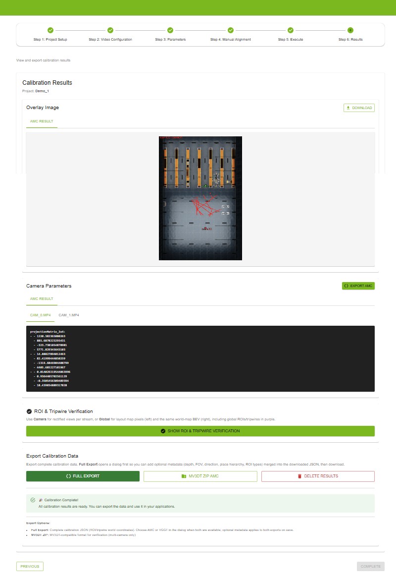
Step 6: Results#
View calibration results, evaluate accuracy, and export calibration data.
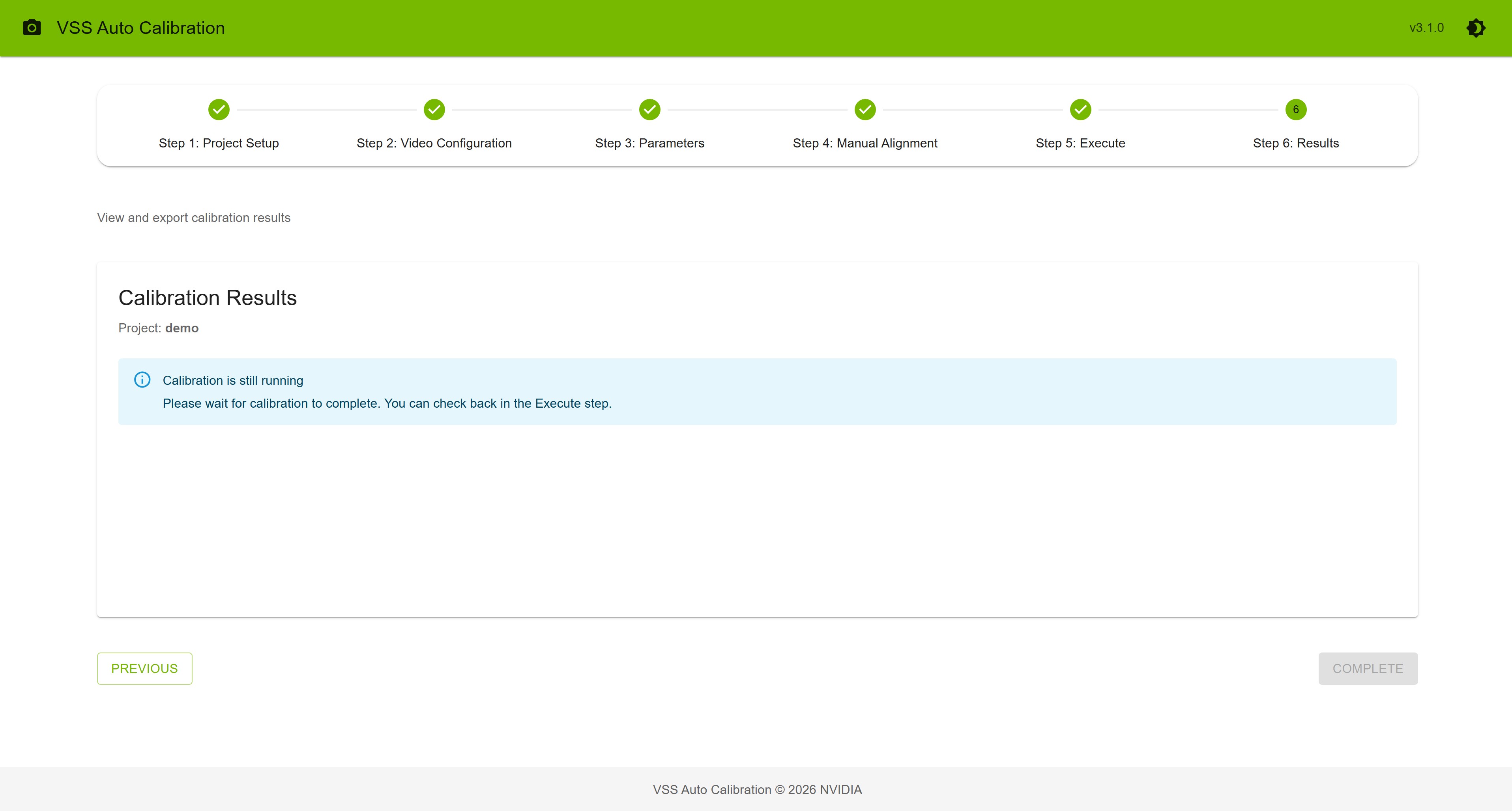
Results Availability#
The Results step is available when at least one calibration path has completed successfully:
AMC completed successfully, or
VGGT completed successfully (even if AMC failed earlier—for example during multi-view tracklet matching)
When VGGT alone succeeds, the overall project state is COMPLETED and you can open Results and use the VGGT tab for overlays, parameters, and exports. AMC tabs remain available only when AMC produced usable outputs.
If No Results Are Available Yet
You’ll see an alert message such as:
Running: “Calibration is still running - Please wait for calibration to complete.”
Error: “Calibration failed - Please check your input files and try again.” (if neither AMC nor VGGT has completed)
Init/Ready: “Please run calibration in the Execute step”
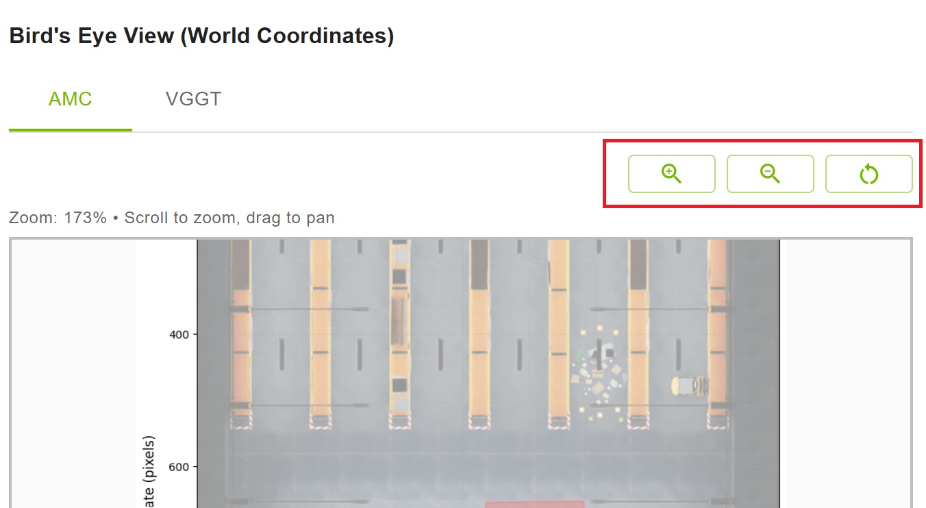
Overlay Image#
The overlay image shows the calibration results projected onto the layout map.
Features
View: Displays cameras’ fields of view on the layout
Download: Save the overlay image to your computer
Result Type Tabs: Switch between AMC and VGGT results (if available)
How to View
The overlay image loads automatically
Use the tabs to switch between AMC and VGGT results
Click “Download” button to save the image
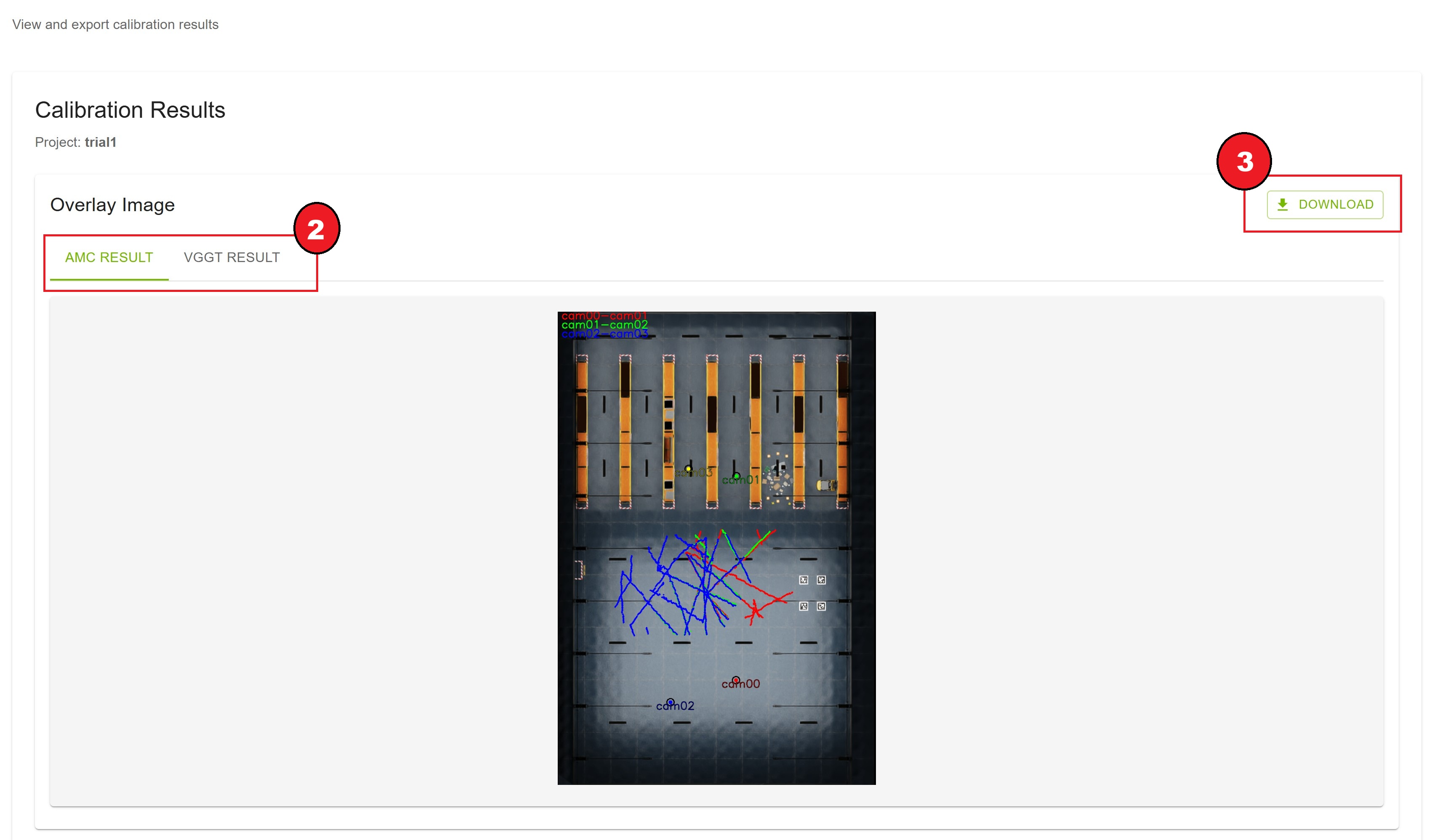
Result Type Selection
AMC Result tab: Shows AMC calibration overlay
VGGT Result tab: Shows VGGT calibration overlay (if available)
VGGT tab is disabled if VGGT calibration was not run
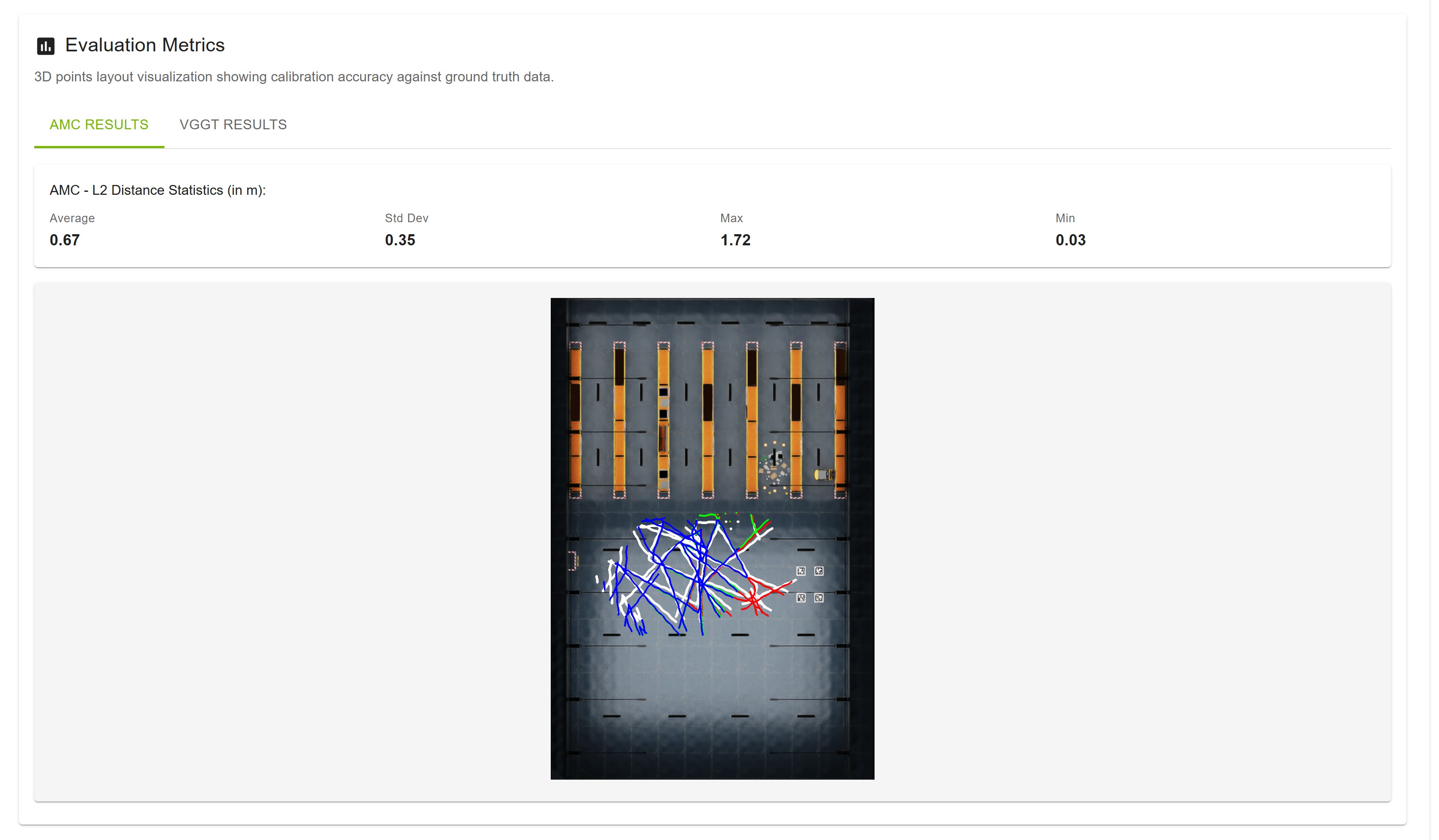
Evaluation Metrics#
If ground truth data was uploaded, evaluation metrics are available.
Metrics Display
Layout Visualization: 3D points plotted on layout showing accuracy
Statistics Card: L2 distance statistics in meters
Average L2 distance
Standard deviation
Maximum distance
Minimum distance
Result Type Tabs: Switch between AMC and VGGT evaluation
Interpreting Metrics
Lower Average: Better calibration accuracy
Lower Std Dev: More consistent calibration
Compare AMC vs VGGT: VGGT typically shows improvement
Note
Evaluation metrics are only available if ground truth data was uploaded in Step 2.
Camera Parameters#
View detailed calibration parameters for each camera.
Features
Camera Tabs: Switch between cameras (Camera 0, Camera 1, etc.)
Result Type Tabs: Switch between AMC and VGGT parameters
YAML Format: Parameters displayed in YAML format
Export Button: Export all camera parameters
How to View
Click on a camera tab (e.g., “Camera 0”)
Parameters load and display in a code block
Switch between AMC and VGGT tabs to compare
Click “Export AMC” or “Export VGGT” to download all parameters
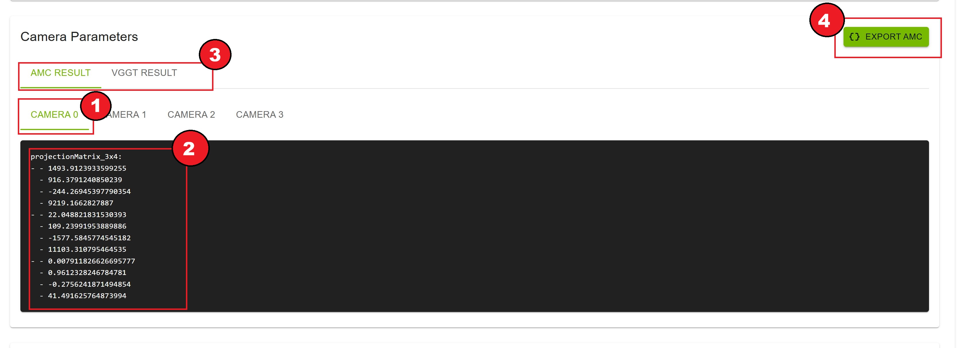
Parameter Contents
The YAML file contains:
Camera Projection Matrix (3X4): Camera projection matrix
Additional Metadata: Project ID, timestamp, etc
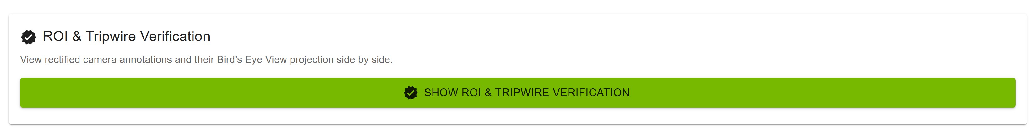
ROI & Tripwire Verification#
Verify per-camera and global ROIs and tripwires: how they appear on each rectified stream, on the layout map (pixel space), and on the world map (BEV) after calibration projection.
Features
Side-by-side layout: Left panel (camera or layout map) and World map (layout + projection) on the right
Annotation target: Camera (per-stream rectified view) or Global ROIs / tripwires (layout
layout.pngpixels; requires layout from Step 2)Result type tabs (right panel): AMC or VGGT world-map projection when both calibrations completed
Global features on world map: Global ROIs and tripwires projected into world coordinates and drawn in purple on the BEV
Global features on camera view: The same global ROIs/tripwires re-projected onto the selected camera when visible in that field of view—also purple
Sensor assignment checkboxes (camera target): Include or exclude the selected camera from each global ROI/tripwire
sensorslist in the export JSON.
How to Use
Click Show ROI & Tripwire Verification
Choose Camera or Global ROIs / tripwires in the annotation target toggle
Camera target: pick a stream from Select Camera; review the left rectified frame and the right world map; use AMC / VGGT tabs on the world map as needed
Global target: left panel shows global shapes on layout.png (pixel coordinates); right panel shows their world-map projection in purple
Under the camera view, use checkboxes labeled Global ROI: / Global tripwire: to include or exclude that camera in each ROIs/Tripwires
sensorslist (only global items projected to that camera are listed)Use world-map zoom controls for detail; click Close when finished
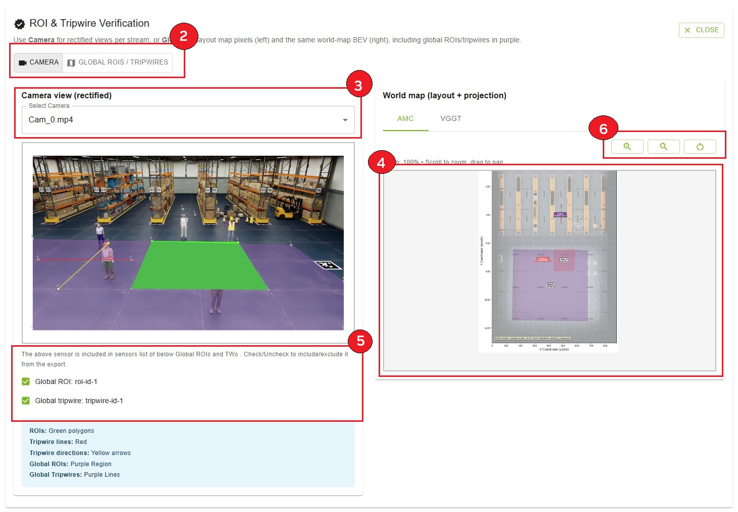
Left Panel — Camera target
Rectified video frame for the selected camera
Per-camera annotations: ROIs (green polygons), tripwire lines (red), tripwire directions (yellow arrows)
Global ROIs (purple regions) and global tripwires (purple lines) when they project into this camera’s view
Global sensor checkboxes: For each global ROI/tripwire that applies to this camera, check to keep the camera in that feature’s
sensorslist in the export JSON; uncheck to exclude it
Left Panel — Global target
Layout map (pixel coordinates): Same global ROIs and tripwires drawn in Parameters on
layout.png(green / red / yellow in layout space)Compare with the right panel to confirm world projection matches the layout drawing
Right Panel — World map (layout + projection)
Bird’s-eye / world-coordinate map with all projected annotations for the active AMC or VGGT result
Per-camera ROIs and tripwires for all streams, plus global ROIs and tripwires in purple
Zoom: 50% to 500%; pan by dragging when zoomed
Zoom Controls
Zoom In (🔍+): Increase zoom level
Zoom Out (🔍-): Decrease zoom level
Reset (↻): Return to 100% zoom
Current Zoom: Displayed as percentage
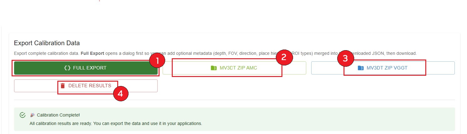
Export Calibration Data#
Export complete calibration data in various formats.
Export Options
Full Export
One control on the Results page; opens a dialog for optional metadata and download
Complete calibration JSON with ROI/tripwire world coordinates
Choose AMC or VGGT inside the dialog when both calibrations completed (toggle: Download / edit AMC export vs Download / edit VGGT export); otherwise the available result type is used automatically
AMC uses the AMC projection matrix; saved/downloaded as
{project_name}_exported.json(browser download may show ascalibration.json)VGGT uses the VGGT projection matrix (multi-camera, when VGGT completed); saved/downloaded as
{project_name}_exported_vggt.json
MV3DT ZIP AMC
MV3DT-compatible format for verification
ZIP archive with all necessary files
Filename:
{project_name}_mv3dt.zip
MV3DT ZIP VGGT (if available)
MV3DT-compatible format with VGGT results
ZIP archive with all necessary files
Filename:
{project_name}_vggt_mv3dt.zip
Delete Results
Removes all calibration results
Project returns to READY state
Allows re-running calibration
How to Export
Full Export: Click Full Export, choose AMC or VGGT in the dialog when both are available, optionally edit metadata or open the manual JSON editor by clicking Full Control, then click Download JSON. The file downloads to your browser’s download folder.
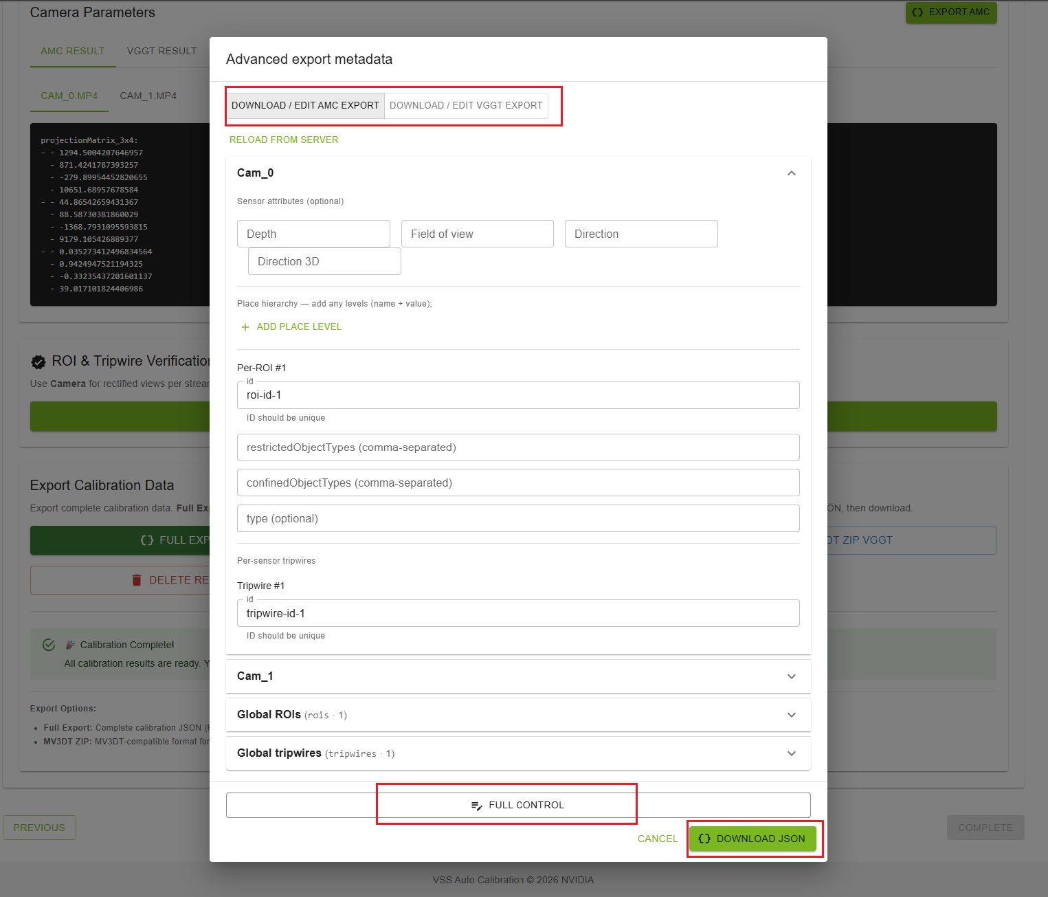
Note
This is an advanced user feature. Edit the JSON only if you understand the calibration schema; any changes should be made carefully to avoid invalid or incorrect calibration output.
Other exports (MV3DT ZIP):
Click the desired export button
Wait for processing (may take a few seconds)
File downloads automatically to your browser’s download folder
Success message confirms export
Note
Export Options Explained:
Full Export: Complete calibration with ROI/tripwire world coordinates; pick AMC or VGGT in the dialog when both exist
MV3DT ZIP: MV3DT-compatible format for verification (separate AMC and VGGT buttons)
Deleting Results#
If you need to re-run calibration with different parameters:
Click “Delete Results” button
Confirm deletion in the dialog
All calibration results are removed
Project state returns to “READY”
Files (videos, layout, alignment) remain uploaded
Warning
Deleting results cannot be undone. Export important data before deletion.
Completion Message#
At the bottom of the page, you’ll see a success message:

Message
Title: “🎉 Calibration Complete!”
Text: “All calibration results are ready. You can export the data and use it in your applications.”
How to Interpret Calibration Outputs#
Upon completion of the calibration process, the UI presents the results including overlay images and various metric numbers, depending on whether ground truth data was provided.
Case 1: Ground Truth Data Exists
If ground truth data was uploaded during the project setup, the tool calculates the L2 distance as the primary evaluation metric. The L2 distance is defined as the Euclidean distance between the 3D ground truth object location and the estimated location determined by triangulation.
The UI displays the following statistics for the L2 distance:
Average: Mean L2 distance across all points
Standard Deviation: Measure of consistency
Maximum: Worst-case error
Minimum: Best-case error
Since a lower L2 distance indicates better accuracy, users can compare these metrics between the AMC and VGGT results to select the superior calibration.
Additionally, the calibration results from the two methods can be compared visually using the overlay visualization. In this image, the object trajectories reconstructed using the camera matrices are shown as colored lines. The ground truth trajectories are displayed in white. A close alignment of the colored trajectories with the white lines signifies accurate camera parameters.
Note
When comparing AMC and VGGT results:
Look for lower L2 distance values (better accuracy)
Compare overlay images for trajectory alignment
Check consistency of colored lines with white ground truth lines
Case 2: No Ground Truth Data
When ground truth data is unavailable, calibration results can be compared qualitatively. One approach is to compare overlay images generated by different methods.
These overlay images display:
Reconstructed object trajectories: Shown as colored lines
Estimated camera locations: Shown as colored dots with corresponding camera IDs
By comparing the relative positions of the cameras and object trajectories against the floor map, one can determine the superior result.
Qualitative Evaluation Tips:
Camera positions should match expected physical locations
Object trajectories should follow logical paths on the floor map
FOV (Field of View) boundaries should align with physical constraints
Compare AMC and VGGT overlays to identify which better matches the layout
Best Practices#
Reviewing Results
Check overlay image for proper camera coverage
Verify evaluation metrics if ground truth is available
Compare AMC and VGGT results if both available
Review camera parameters for reasonableness
Exporting Data
Export both AMC and VGGT results for comparison
Keep MV3DT ZIP for verification purposes
Store exports with descriptive names and dates
Maintain backups of important calibration data
Verification
Always verify ROI/tripwire projections
Check all cameras, not just one
Use zoom to inspect details
Compare AMC vs VGGT projections
Before Deleting
Export all needed data first
Verify exports are complete and valid
Document any issues or observations
Consider keeping project for reference
Next Steps#
After completing calibration:
Use exported data in your surveillance application
Integrate calibration parameters with your tracking system
Set up ROIs and tripwires in your production environment
Monitor and validate calibration accuracy in real-world scenarios